BETRIEBSANLEITUNG
Operating Instructions • Instructions de service
D A CH ACHTUNG! Nicht für Kinder unter 3 Jahren geeignet wegen funktions- und modellbedingter
scharfer Kanten und Spitzen, Verschluckungsgefahr. GB WARNING! Not suitable for children under 3
years of age due to the functional sharp edges and points required in this model. Danger of swallowing F
AVERTISSEMENT! Ne convient pas pour des enfants de moins de 3 ans, en raison des fonctions
d’utilisation et des formes à arêtes tranchantes du modèle. Danger d’apsorption. NL WAARSCHUWING!
Niet geschikt voor kinderen onder de 3 jaar vanwege funktionele en/of modelgewenste scherpe randen
en punten. Verslikkingsgevaar. I AVVERTENZA! Non adatto ai bambini di età minore di 3 anni a causa de-
gli spigoli e delle parti sporgenti. Pericolo di soffocamento. E ADVERTENCIA! No apropriado para niños
de menos de 3 años, debido a que este modelo requiere cantos y puntos funcionales agudos. Peligro de
que sea ingerido. DK ADVARSEL! Er ikke egnet til børn under 3 år, p. g. a. funktions- og modelbetingede
skarpe kanter og spidser, - kan slugos. P AVISO! Não conveniente para crianças sob 3 anos devido às
bordas agudas funcionais e pontos exigiram neste modelo assim como perigo de engolir. GR ΠΡОΣΟΧΗ. Τά
πεχνιδια. αύτâ δέν επητρέποναι σέ παιδιά κάτο τών З χρόνων διότη ε´Ιναι κοφτερα καί εχμηρά καί κùνδηνος νά τά καταπιουν SF VAROITUS! Ei
sovellu tukehtumisvaaran vuoksi alle 3-vuotiaille lapsille. Sisältää toimivuuden ja muotoilun kannalta oleel-
lisia teräviä reunoja ja piikkejä. S VARNING! Inte ägnat för barn under 3 år därför att där finns spetsor och
vassa kanter och fara för sväljning. CZ VAROVÁNÍ! Nevhodné pro dĕti do 3 let: funkční díly mají ostré
hrany a špičky, nebezpečíspolknutí malých součástek a dílů. Uchovávejte a dodržujte toto upozornĕní.
PL OSTRZEŻENIE! Zabawka ze wzgledu na cechy dzialania, budowe modelu z ostrymi krawedziami oraz
mozliwoscia polkniecia mniejszych czesci nie jest przystosowana dla dzieci ponizej 3 lat. SLO OPOZO-
RILO! Ni primerno za otroke do 3 leta starosti zaradi funkcionalno ostrih robov in konic, kot tudi nevarno-
sti pozrtja.
12.1 M 21/6454-0101
GEBR. FLEISCHMANN GMBH & CO. KG
D-91560 Heilsbronn, Germany
www.fleischmann.de
14 V
Bitte gehen Sie beim Einbau wie folgt vor:
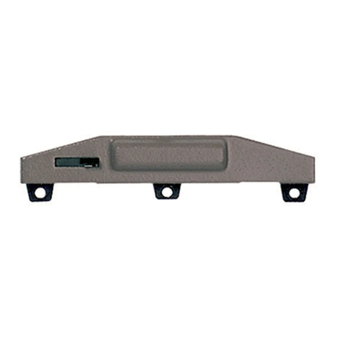
1. Mit Daumen und Zeigefinger die Radkontakt-
feder am Kunststoffteil greifen. Dabei die
Kunststoffklammern mit dem Daumen leicht
andrücken (Fig.1).
2. Die Radkontaktfeder in die Drehgestellöffnung
einführen und durch Festdrücken einrasten
lassen (Fig.2). Darauf achten, dass die beiden
Radkontakte an den Radinnenseiten anliegen.
Auf diese Weise alle vier Radkontaktfedern
montieren. Fig.1
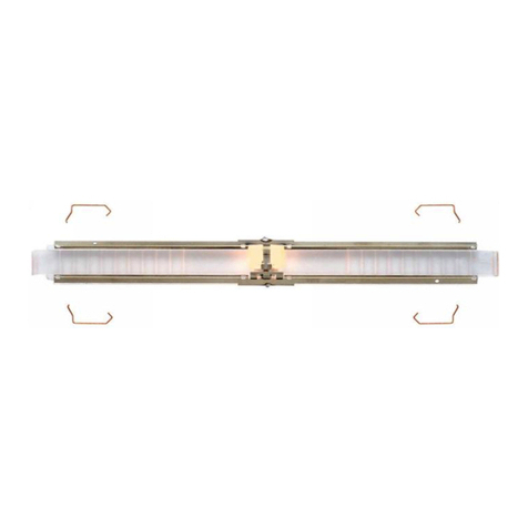
6454 Innenbeleuchtung für Reisezugwagen mit einer LüP von 282mm
Wichtig: Es liegen 8 Kontaktbügel bei. Die vier kürzeren Bügel sind ausschließlich für den
Nahverkehrswagen „modus“ (Artikel-Nr. 5654) zu verwenden.
Zur Montage der Radkontaktfedern ist eine Demontage der Drehgestelle nicht erforderlich!
Achtung: Vor dem Einbau der Innenbeleuchtung die Betriebsanleitung genau durchlesen!
Attention: Please read the instructions carefully before installing the interior lighting!
Attention: Avant le montage de l’éclairage interieur lire soigneusement le mode d’emploi!
6454 Interior lighting for passenger coach with overall length of 282 mm
Important: Enclosed you’ll find 8 contact bars. Please use the four shorter ones only for the local
coach ”modus“ (Art. no. 5654). It is not necessary to take off the bogies!
1. Grip the wheel contact spring on the plastic part between thumb and forefinger. In doing so, press the
plastic clips gently with the thumb (Fig.1).
2. Insert the wheel contact spring into the opening in the bogie and press firmly into position (Fig.2).
Make sure that both wheel contacts are positioned on the inside of the wheels. Assemble all four
wheel contact springs in this manner.
3. The coach body has to be removed before assembling the optical fibre. In the area of the bogies, push
fingernails inbetween the coach body chassis and prise open the coach body (Fig.3). The coach body
will part from the chassis and can be lifted off upwards.
Local coach ”modus“ (Art. no. 5654): Insert two screwdrivers gently into the slots located near the
bogies, in between the chassis and body sides (Fig4). Press down gently with finger pressure on the
buffers and also gently twist the screwdriver. Keep the finger pressure on the buffers, and insert the
screwdriver in sequence into the slots (X) as before to separate the chassis from the body.
4. Fit light bulb into optical fibre. To do this, lay the glass bulb of the lamp into the recess underneath lug
H(Fig.5a) and clamb the wire ends to the two terminal contacts. Lay the free wire ends around the
optical fibre.
5. Stick first (after removing protective backing from the adhesive side) the white insulating foil then the
metal foil around the optical fibre (Fig.5b).
6. Lay the optical fibre onto the internal works in such a way that the digits (for ex. „12/4021“) are on the
side of the carriage with the recesses A(Fig.6). The bars Ssecure the optical fibre on the internal
works against being moved longitudinally.
7. Each set of internal works has – in different places depending on carriage type – four mountings for
the contact bars. The contact bars ensure secure mounting of the optical fibre on the internal works,
as well as supplying it with electricity. First loosely fit the contact bar at the bottom into recess aof the
internal works, then hook it onto pin Z(Fig.7). Pull the contact bar down a little and lock it onto step V.
8. Replace the coach body and clip back into place.
Attention: The step Nmust be located at the side of recess A(Fig.6).
6454 Garniture d’éclairage intérieur pour voitures avec Lht de 282 mm
Important: Comme accessoires il y a 8 étriers de contacts. Les quatre étriers plus courtes sont
prévues seulement pour la voiture de réseau régional ”modus“ (réf. 5654). Il n’est pas nécessaire
de démonteur les bogies!
1. Prenez la pièce en plastique des contacts de roues au moyen du pouce et de l’index. Ecrasez légère-
ment les arrêts en plastique avec le pouce (Fig.1).
2. Engagez les contacts de roues dans l’ouverture du bogie et assurez la fixation en appuyant (Fig.2).
Veillez à ce que les contacts portent sur la face intérieure des roues. Procédez de la même manière
pour monter les quatre contacts de roues.
3. Pour le montage de la platine-lumière il est nécessaire d’enlever la carrosserie de la voiture. Introduire
les ongles entre la carrosserie et le chassis à l’emplacement du bogie (Fig.3). La carrosserie peut ainsi
se séparer du chassis et être retirée.
Pour la voiture de réseau régional ”modus“ (réf. 5654): Glisser d’abord deux tournevis à hauteur de
l’un des bogies dans les fentes latérales prévues à cet effet entre la plate-forme et la caisse (Fig.4).
Avec les doigts, tirer la plate-forme vers le bas en agissant au niveau des heurtoirs et la libérer en
écartant légèrement les tournevis. Maintenir ainsi la plate-forme par les heurtoirs et finir de la séparer
en introduisant successivement les tournevis dans les autres fentes (X) repérées à cet effet.
4. Placez la lampe sur la platine. Logez le bulbe de la lampe dans l’évidement sous le support H
(Fig.5a), fixez les aux deux contacts. Glissez le surplus de fils sous la platine.
5. Collez d’abord l’isolant (enlevez les protections des faces adhésives au préalable), ensuite la feuille
métallique à la platine (Fig.5b).
6. Placez la platine sur la garniture intérieure de façon à ce que le marquage (par ex. „12/4021“) se situe
du côté de la voiture où se trouvent les évidements A(Fig.6). Les éléments Sévitent le déplacement
longitudinal de la platine sur la garniture intérieure.
7. Chaque garniture intérieure présente – à différents endroits selon le modèle – quatre places pour les
étriers de contacts. Les étriers de contacts maintiennent la platine conductrice sur la garniture inté-ri-
eure et en assure l’alimentation électrique. Disposez en premier lieu l’étrier dans l’évidement aet acc-
rocher au tenon Z(Fig.7). Tirez légèrement l’étrier vers le bas et fixez sur la partie en saillie V.
8. Remontez la carrosserie et assurer son verrouillage.
Attention: La partie en saillie Ndoit se trouver du côte des évidements A(Fig.6).
G
F
