AeroVonics AV-20 Manual

D-0014-0, AV-20 Pilots Guide
4/2/2018 Page 1 of 29 Revision B
AV-20 / AV-20-S
Multi-Function Display
Part Number U-1001-0 / U-1002-0
Pilot’s Guide
(D-0014-0, AV-20, PILOTS GUIDE, REV B)
AeroVonics LLC
12306 Menaul Blvd NE.
Albuquerque, New Mexico 87122

D-0014-0, AV-20 Pilots Guide
4/2/2018 Page 2 of 29 Revision B
Document Revisions
Revision
Date
Description of Change
Author
PDF Sig
A
9/20/2017
Initial Release
JDB
B
4/2/2018
Updated for initial NORSEE certification, latest
UI for Software Release 1.0
JDB
Table of Contents
1. System Description.......................................................................................................................4
1.1. Angle of Attack ..................................................................................................................5
1.2. G Meter..............................................................................................................................5
1.3. Attitude ..............................................................................................................................5
1.4. Clock/Run Time.................................................................................................................6
1.5. Outside Air Temperature...................................................................................................6
1.6. Bus Voltage .......................................................................................................................6
1.7. Dual User Timers...............................................................................................................6
1.8. Engine Run Timer .............................................................................................................6
1.9. Flight Timer........................................................................................................................6
1.10. User Setup.........................................................................................................................7
1.11. Battery Operation ..............................................................................................................7
1.12. Model Functionality ...........................................................................................................8
2. Operating Limits............................................................................................................................9
3. Power-On Stabilization .................................................................................................................9
4. User Interface Overview .............................................................................................................10
4.1. User Interface Controls ...................................................................................................10
4.2. Page Navigation..............................................................................................................10
4.3. View Button .....................................................................................................................10
4.4. Left & Right Push ............................................................................................................11
4.5. Splash Screen .................................................................................................................11
4.6. Screen Brightness...........................................................................................................12
5. Main Pages.................................................................................................................................13
5.1. Clock Combo Page .........................................................................................................13
5.2. FE Time - Flight Time, Engine Time Page......................................................................14
5.3. User Timer Pages ...........................................................................................................15
5.3.1. Count-Up Mode...................................................................................................................15
5.3.2. Count-down Mode...............................................................................................................15
5.3.3. Mode Transition ..................................................................................................................17
5.4. AOA/G Meter Page .........................................................................................................18
5.4.1. Large AoA Display Mode ....................................................................................................18
5.4.1. Large G-Meter Display Mode..............................................................................................19
5.4.2. Dual Graph Mode................................................................................................................20
5.5. Attitude Page...................................................................................................................21
5.6. Setup Pages....................................................................................................................22
5.6.1. Setup – Top Level Menu.....................................................................................................22
5.6.2. Setup – System Info............................................................................................................23
5.6.3. Setup - Page Enable...........................................................................................................23
5.6.4. Setup – Audio Alerts ...........................................................................................................24
5.6.5. Setup – Audio Volume ........................................................................................................24
5.6.6. Setup – OAT Trim...............................................................................................................24
Digitally
signed by JDB

D-0014-0, AV-20 Pilots Guide
4/2/2018 Page 3 of 29 Revision B
5.6.7. Setup – Miscellaneous Options...........................................................................................25
5.6.8. Setup – AoA Limits .............................................................................................................26
5.6.9. Setup – G Limits .................................................................................................................26
5.6.10. Setup – Hard Calibration.....................................................................................................26
6. Audio and Visual Alerts...............................................................................................................28
6.1. Alert Prioritization ............................................................................................................28
6.2. Clearing Alerts.................................................................................................................29

D-0014-0, AV-20 Pilots Guide
4/2/2018 Page 4 of 29 Revision B
1. System Description
The AeroVonics AV-20 and AV-20-S Multi-Function Display provides a wide array of
supplemental flight information. The AV-20 provides 9 functions, while the AV-20-S model
provides 11 functions.
Features Include:
AoA Display (Voice Alerting & Peaks)
G-Meter Display (Voice Alerting & Peaks)
Attitude (Roll / Pitch)
Clock (GMT / Local)
Outside Air Temperature (C / F)
Bus Voltage Display
Dual User Timers (Count Up / Down)
Engine Run Timer
Flight Timer
Density Altitude Display
True Airspeed Display (Kts / Mph)
Internal Battery Operation
The unit incorporates a full color sunlight readable display, bezel-mounted light sensor for
automatic display brightness, and an internal battery for operation in the event of power
loss. The AV-20-S connects to the pitot and static systems of the aircraft, while the AV-20
model does not.
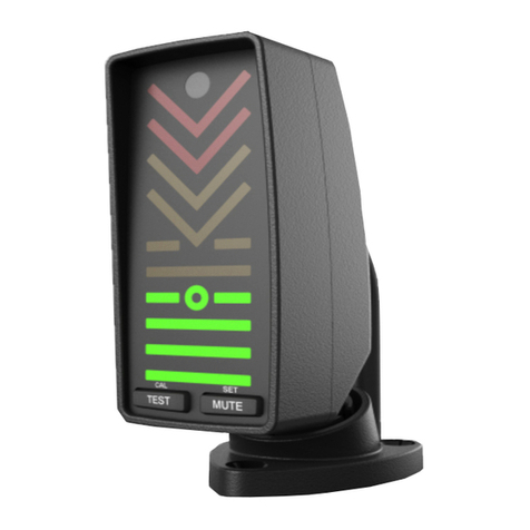
Figure 1 - AV-20 and AV-20-S

D-0014-0, AV-20 Pilots Guide
4/2/2018 Page 5 of 29 Revision B
Intended functionality is as follows:
1.1. Angle of Attack
Angle of Attack is derived from pitot and static pressure measurements combined with
internal inertial reference measurements. No dedicated external probes or other aircraft
modifications are required for AoA functionality.
AoA is computed based on the difference between aircraft pitch angle, and the aircrafts
path angle through the air, and current G loading.
An upper “near-stall” calibration point is set by the pilot and represents the desired
alerting / maximum scale point. A lower calibration point represents the nominal
“cruise” AoA and is used to set the lower boundary of the AoA scale. The amount of
pre-warning for an AoA alert prior to the certified aircraft stall point is based on pilot
preference.
Both visual and aural alerting is provided when the AoA is approaching or exceeds the
upper calibration point. AoA and associated alerting is only available on the AV-20-S
model. AoA information is not for primary aircraft control and is provided for
supplemental situational awareness only.
1.2. G Meter
G Load is determined via the internal inertial sensors and will measure up to 8G in
either direction. Independent positive and negative G limits are configurable, with both
visual and aural alerting being provided. Peak negative and positive G Loads are also
measured for display.
The range of the color-coded G scale is automatically scaled based on the pilot
configured limits such that the maximum indication (positive or negative) represents the
maximum value configured. G-Meter and associated alerting is available only on the
AV-20-S model. G Load information is not for primary aircraft control and is provided
for supplemental situational awareness only.
1.3. Attitude
Attitude (Roll & Pitch) is determined from the internal inertial sensors. AoA can be
overlaid on the attitude indicator page. A pitch-zero feature allows the current pitch
angle to be trimmed to zero, allowing synchronization with other on-board
instrumentation.
Attitude accuracy is better than 1° under stable conditions and better than 2.5° under
dynamic flight conditions. Airspeed is utilized to help stabilize pitch during takeoff,
landing and extended accelerations. Attitude is only available on the AV-20-S model.
Attitude information is not for primary aircraft control and is provided for supplemental
situational awareness only.

D-0014-0, AV-20 Pilots Guide
4/2/2018 Page 6 of 29 Revision B
1.4. Clock/Run Time
Clock functions include display of time in local and GMT time zones and can be set by
the pilot. A local offset value determines the difference between the GMT and local
time zone. The clock is internally backed up via an internal battery which automatically
recharges during flight. The clock function is available in both the AV-20 and the AV-20-
S models.
1.5. Outside Air Temperature
OAT is measured by an external temperature probe and is displayable in either Celsius
or Fahrenheit. OAT is available in both the AV-20 and the AV-20-S models.
OAT data is also utilized in the computation of TAS and Density Altitude and must be
connected for those data parameters to be displayed, however, as these parameters
also require pressure measurements, they are only available on the AV-20-S model. A
compatible OAT probe must be installed for OAT related features to be enabled.
1.6. Bus Voltage
Bus voltage is measured directly from the powered supply lines and displayed on the
clock combo page. Bus voltage is available in both the AV-20 and the AV-20-S models.
1.7. Dual User Timers
Dual independent timers are available for general purpose usage. Each timer can be
configured as a count-up or count-down timer, with both a visual and aural alert when
the count-down goes to zero. Resolution of the timers is 1 second. User timers are
available in both the AV-20 and the AV-20-S models.
1.8. Engine Run Timer
The engine run timer initiates counting based on bus voltage increasing above the no-
load battery voltage (alternator running), and special switching logic accommodates
both 12V and 24V aircraft. The timer can be reset by the pilot.
The engine run timer is not maintained between power-cycles, and does not represent
a HOBBS type function. The engine run timer is available in both the AV-20 and the AV-
20-S models.
1.9. Flight Timer
The flight timer initiates counting based on airspeed above 40 kts and can be reset by
the pilot. The timer will stop counting when the speed is below the threshold.
The flight timer is not maintained between power-cycles. The flight timer is only
available on the AV-20-S model, as airspeed switching is not available on the AV-20.

D-0014-0, AV-20 Pilots Guide
4/2/2018 Page 7 of 29 Revision B
1.10. User Setup
The pilot accessible setup menu can be used to easily configure an array of instrument
parameters. All parameters are configurable by the pilot, with certain functions being
inhibited during flight.
Options include display color choice, page enable/disable, audio alerts enable/disable,
audio volume, OAT trim, temperature units, time units, airspeed units, alert popup
behavior, AoA thresholds and G alert limits.
1.11. Battery Operation
The unit incorporates a small Li-Po battery that can operate the unit for approximately
30 minutes under normal ambient temperatures. If external power is lost and airspeed
is above 40 kts, the unit will automatically transition to internal power with no pilot action
required. When airspeed drops below 40 kts, a normal shutdown will occur. This
feature is only available on the AV-20-S model.
This battery is also utilized to maintain the clock time. Therefore, if battery operation
continues to the point of battery depletion, the clock may need to be reset on the next
power-up.
Note that the AV-20 also incorporates the identical battery but is not utilized for
operation when external power is lost, only for clock keep-alive functionality.
The battery is automatically recharged during normal operation.

D-0014-0, AV-20 Pilots Guide
4/2/2018 Page 8 of 29 Revision B
1.12. Model Functionality
The AV-20 is available in two configurations:
The AV-20 model, which does not include internal inertial sensors or pitot-static
sensors. Functions are limited to those indicated below.
The AV-20-S model, which includes the AV-20 base model functions, plus the
features gained from the full sensor set. Full functionality is available in this
configuration.
Feature / Model
AV-20
AV-20-S
Clock
OAT
Bus Voltage
Dual User Timers
Engine Run Timer
Flight Timer
AoA
Attitude
Density Alt
True Airspeed
G-Meter
Battery Operation
Audio Alerts
Timer Alert
AoA Alert
G Limit Alert
Table 1 - Functional Dependencies
The unit model and associated part number is shown on the splash screen
on power-up.

D-0014-0, AV-20 Pilots Guide
4/2/2018 Page 9 of 29 Revision B
2. Operating Limits
The AV-20 and AV-20-S are supplemental systems and may not be
used as a substitute for any system on a certified aircraft. No
operational credit may be taken for installation of this equipment.
The following operational limitations are applicable:
Operating Limits
Angle of Attack Range
0° to +30°
Angle of Attack Resolution
1°
Angle of Attack Operation
+35 to +300 Knots
Angle of Attack Accuracy
2.5°
Density Alt Range (Accuracy)
-1,000 to +25,000 Feet (± 500ft)
TAS Range (Accuracy)
+35 to +300 Knots (± 20 kts)
Attitude Angle
No Limits
Attitude Rate Limit
±250 Degrees / Second
Attitude Accuracy
1° Static, 2.5° Dynamic
G Alert Limits
± 8 g
OAT Range
-40°C to + 70°C
OAT Accuracy
±4°C
Bus Voltage Range
7 to 35 Volts
Bus Voltage Accuracy
±1.0 Volt
Clock Accuracy
± 1 Second/Day
Timer Accuracy
± 1 Second/Hour
Table 2 - Operating Limits
Refer to the AV-20 Installation Manual for Instructions for Continued
Maintenance & Operation.
3. Power-On Stabilization
The AV-20-S model incorporates precision air data and inertial sensors that are
temperature-sensitive. These sensors are thermally stabilized by an internal heater.
During power-on, the heater warms the sensors to the operating temperature; thus, they
require a few moments to stabilize.
During this power-on stabilization period, AoA, Attitude and Air Data-related parameters are
not available. These values will be flagged on each page, as described in the User
Interface section of this document.
Typical stabilization time is between 30 seconds and 1 minute, depending on the ambient
starting temperature of the unit. If the unit takes longer than 60 seconds to perform the
power-on stabilization, a hard calibration should be performed (See section 5.6.10).

D-0014-0, AV-20 Pilots Guide
4/2/2018 Page 10 of 29 Revision B
4. User Interface Overview
4.1. User Interface Controls
Controls for the AV-20 consist of three bezel-mounted momentary-push buttons. The
functionality of the buttons changes based on the current mode. User interface
components are as follows:
Photo Cell
View Button
(Changes View
Mode, or other
related action)
Left Control
Button
Right Control
Button
(Hold for manual
brightness adjust)
BOTH - Less Often Used Functions
(Push Left and Right Buttons Together)
Page
Navigation
Area
BOTH
Function
Indication
SET
4.2. Page Navigation
The Left and Right Control Buttons navigate through the different pages. The position
of the displayed page is shown graphically at the bottom of the page as a set of bars on
the left and right sides. The following graphic indicates that there are two pages to the
“left” and five pages to the “right”.
4.3. View Button
The VIEW button selects different viewing options for the current page, or performs
another function relative to the page selected.

D-0014-0, AV-20 Pilots Guide
4/2/2018 Page 11 of 29 Revision B
4.4. Left & Right Push
Momentarily pushing both the LEFT and RIGHT control buttons together performs
various tasks that are rarely used, such as setting values. If this option is available for a
given display, the function name will be displayed centered above the BOTHtext on
the bezel.
EXAMPLE: The following image shows that a SET function can be performed by
pressing both control buttons:
If no text appears in this area, no action is assigned to the BOTHcommand for this
page.
4.5. Splash Screen
The system splash screen is displayed on power-up. The unit model (AV-20 or AV-
20-S) is shown, along with the software version number. The unit also displays the
splash screen momentarily on power-down.
Shows Model
Number
Shows Software
Version
AV-20-S

D-0014-0, AV-20 Pilots Guide
4/2/2018 Page 12 of 29 Revision B
4.6. Screen Brightness
Pressing and holding the lower right button will display the screen brightness page. By
default, the screen is set to auto brightness mode and will utilize the light detected by
the photocell to set the screen brightness.
Pressing either the up or down arrows will transition the unit to manual mode.
Pressing either
will transition
to manual
mode
Accepts the
currently set
level
SCREEN
BRIGHTNESS
AUTO MODE
When in manual mode, pressing the up or down arrows will adjust the screen
brightness. Pressing the right button will accept the value. Pressing BOTHwill
revert to auto mode.
Increases or
decreases
brightness
SCREEN
BRIGHTNESS
MANUAL MODE
Accepts the
currently set
level
BOTH Sets back to Auto Mode

D-0014-0, AV-20 Pilots Guide
4/2/2018 Page 13 of 29 Revision B
5. Main Pages
5.1. Clock Combo Page
The Clock Combo Page displays multiple items of information as shown below. The
VIEW button sequences through available data in the upper field. Note that the screen
layout and available data will vary based on model and connected sensors.
Density altitude, true airspeed and AoA are not available during power-on stabilization.
Temperature units can be configured to C or F in the setup pages.
CLOCK COMBO PAGE
VIEW Toggles upper
field contents:
-Local Time
-GMT Time
-Density Altitude*
-True Airspeed*
* -S Model, with OAT probe
connected
BOTH Sets Time (When Local or GMT is displayed)
Angle
Of
Attack
BOTHenters the clock set function when either the local time or GMT time is being
displayed in the upper field. The set mode allows the current GMT time to beset, along
with a local time offset. If time has been lost due to failure of the internal keep-alive
battery, the time will flash.
CLOCK SET MODE
Left upper and lower
button increment or
decrement the current
field (Hours, Minutes,
Seconds, Local offset)
Holding either will
clear field to zero
BOTH Accepts Value
Right button
increments
flashing field to
next position
Currently
highlighted field
will flash

D-0014-0, AV-20 Pilots Guide
4/2/2018 Page 14 of 29 Revision B
Clock combo page layout with base AV-20 model, no temperature probe installed, only
time and bus voltage available for display.
CLOCK COMBO PAGE
AV-20 BASE, NO OAT
Modified screen
layout: Only Local and
GMT Time, no VIEW
options
5.2. FE Time - Flight Time, Engine Time Page
The FE Time page displays (F)light Time and (E)ngine Run Time. These timers are
automatically started and stopped based on measured data. The Flight Time counter
runs when the airspeed speed goes above 40 Kts. The Engine Run Time counter runs
when the bus voltage goes above the basic battery float level (alternator is running).
FE TIME PAGE
VIEW Toggles the
highlighted field,
shown in white
BOTH Clears Highlighted Field to zero
Flight Time
only available
on the –S
model
Either timer can be independently set to zero by selecting it and clearing the value.
Only the engine run time is available on the base AV-20 model, as airspeed
measurements are not available.

D-0014-0, AV-20 Pilots Guide
4/2/2018 Page 15 of 29 Revision B
5.3. User Timer Pages
Two identical user timers are available. Each operates independently of the other and
each can be configured for counting up from zero or counting down from a user-set
value.
5.3.1. Count-Up Mode
In the power-on default state, each timer is a count-up timer. The timer is started
by pressing the VIEW button with the adjacent start icon . When running, this
icon changes to a pause indicator . Pressing the VIEW button again will pause
the timer.
When the timer is paused, pressing and holding the VIEW button will clear the
timer to zero.
VIEW Starts or
pauses the counter
When stopped,
holding button
resets to zero
Timer Number
TIMER PAGE
COUNT-UP MODE
Timer Mode
Only used for
count down
mode
5.3.2. Count-down Mode
Count-down Mode is activated by setting a user-defined value to count down
from. This is accomplished by pressing BOTHto set a value.
When a non-zero value has been set by the user, the timer automatically
becomes a count-down timer. If the set value is changed back to zero, the timer
automatically becomes a count-up timer again.

D-0014-0, AV-20 Pilots Guide
4/2/2018 Page 16 of 29 Revision B
TIMER SET MODE
Left upper and lower
button increment or
decrement the current
field (Hours, Minutes,
or Seconds)
Holding either
momentarily will clear
all fields to zero
BOTH Accepts Set Value
Right button
increments
flashing field to
next position
Currently
highlighted field
will flash
Once the set value is accepted, this value is loaded into both the upper (active)
and lower (Set Value) fields on the timer page.
The lower Set Value allows the same timer value to be reloaded without having
to manually set the value again.
When the timer is stopped, holding the VIEW button will reload the
previously set count-down time.
VIEW Starts or
pauses the counter
When stopped,
holding VIEW will
reload the set value
shown here
Timer Number
TIMER PAGE
COUNT-DOWN MODE
Reload allows
previously set
value to be used
again
Timer Mode
Once the timer is started and the value runs down to zero, a timer alert will be
generated.

D-0014-0, AV-20 Pilots Guide
4/2/2018 Page 17 of 29 Revision B
5.3.3. Mode Transition
Once in the count-down mode, the timer can be changed back to a count-up
timer by setting a value of zero. This can be done manually, or a shortcut can
be used by entering the set mode and holding either of the left buttons down
momentarily. This will clear the HH:MM:SS value to all zeros, making the timer
a count-up timer again.
Timer 1 and Timer 2 operate completely independently of each other and can be
set with different values and operate as either a count-up or count-down.

D-0014-0, AV-20 Pilots Guide
4/2/2018 Page 18 of 29 Revision B
5.4. AOA/G Meter Page
The AoA/G Meter Page has three view modes:
Large AoA Display
Large G-Meter Display
Dual Graph Mode
5.4.1. Large AoA Display Mode
The Large AoA Display mode shows a highly visible indication of the current AoA,
scaled by the configured upper and lower AoA limits (calibration points).
EXAMPLE: If the upper AoA limit has been configured to +12 degrees (near stall),
the upper bar on the display will correspond to this value. If the lower (normal
cruise) AoA limit has been set to +3 degrees, the lower bar will correspond to this
value.
The calibration points are different for each aircraft and are configured in the
setup pages.
AOA/G METER
LARGE AOA MODE
BOTH Clears Peak Values
Peak AoA levels
Current AoA, scaled
to calibration limits
Corresponds to
upper pre-stall
angle
Corresponds to
lower cruise angle
During power-on stabilization, the cyan lower bar will blink, indicating that no valid
AoA can be determined. This applies to all color-coded AoA indications provided
on different pages.
Alerts will be generated just prior to the AoA reaching the upper calibration point.
This display can be configured to automatically pop up when the AoA limit alert
occurs.

D-0014-0, AV-20 Pilots Guide
4/2/2018 Page 19 of 29 Revision B
5.4.1. Large G-Meter Display Mode
The Large G-Meter Display Mode shows an easily readable indication of the
current G load, scaled by both the configured upper and lower G limits. Both
positive and negative values are displayed on the same graph, making the
visible indicator an “absolute” G limit indication.
EXAMPLE: If the upper G limit has been configured to +4 G, the upper bar on
the display will correspond to +4 G. If the lower G limit has been set to -2 G, the
upper bar on the display will correspond to -2 G as well.
The display is scaled appropriately (and differently if needed) for positive and
negative G operations. From the pilot’s perspective, when the meter indicates
near-maximum values, operational limits are being approached.
The positive and negative G limits are configured in the setup pages.
AOA/G METER
LARGE G MODE
BOTH Clears Peak Values
Peak G levels
Current G Load,
scaled to calibration
limits
Corresponds to
absolute G limit,
Positive or
Negative G’s,
scaled to
configured limits
Alerts will be generated just prior to the G load reaching the upper calibration
point.
This display can be configured to automatically pop up when the G-limit alert
occurs.

D-0014-0, AV-20 Pilots Guide
4/2/2018 Page 20 of 29 Revision B
5.4.2. Dual Graph Mode
The dual graph mode is primarily utilized for determining the best upper and
lower AoA calibration points and can be helpful for fine-tuning those thresholds.
The left side of the display shows the current G load, along with the peaks
experienced during the current flight.
The right side of the display shows the current AoA, along with the peaks
experienced during the current flight. Additionally, the configured upper and
lower calibration limits are shown as red and green tic marks. This indicates
where the aircraft’s current AoA is relative to those calibration points.
Current G Force
(White Arrow)
BOTH Clears All Peak Values
Current AoA
(Cyan Arrow)
AOA/G METER
DUAL GRAPH MODE
Negative G-Peak
(Cyan Tic)
Positive G-Peak
(Cyan Tic)
Calibrated Alert Limits
(Red and Green Tics)
AoA Peaks
(Cyan Tics)
To utilize the dual graph mode as an aid for determining the desired
calibration points, the peaks can be cleared while slowing and
approaching the pre-stall condition. Slowly approaching the stall
point will record the peak positive AoA.
Slowly returning the aircraft to normal cruise mode will then record the
peak lower AoA.
These two angles can then be entered as the AoA Limits in the setup
pages.
Other manuals for AV-20
1
This manual suits for next models
1
Table of contents
Other AeroVonics Avionic Display manuals