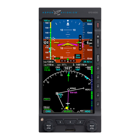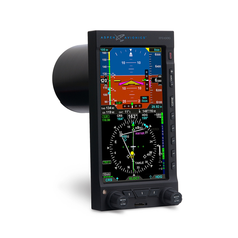
EFD1000 E5 Dual Electronic Flight Instrument (EFI) Install Manual
DOCUMENT # 900-00041-001 PAGE 8-226 REVISION D
© Copyright 2019 Aspen Avionics Inc.
7.1 ELECTRICAL LOAD ANALYSIS .................................................................................... 80
7.2 ELECTRICAL INSTALLATION ...................................................................................... 80
7.2.1 EFD1000 E5...................................................................................................... 80
7.2.2 ACU OR ACU2 (OPTIONAL)..................................................................................... 80
7.2.3 MISCELLANEOUS WIRING ......................................................................................... 80
7.2.4 HIRF/LIGHTNING REQUIREMENTS .............................................................................. 81
7.2.5 EFD TO GPS/VLOC/ACU WIRING ........................................................................... 81
7.2.6 RSM WIRING ....................................................................................................... 82
7.2.6.1 ASSEMBLY USING ASPEN PREFABRICATED 35FT AND OPTIONAL 50FT CABLES .......................... 82
7.2.6.2 ASSEMBLY USING M27500-A24SD7T23 CABLE ......................................................... 82
7.2.6.3 EFD END........................................................................................................... 83
7.2.7 CONFIGURATION MODULE WIRING ............................................................................. 83
7.2.8 ACU WIRING ....................................................................................................... 84
7.2.9 BACK UP NAV INDICATOR WIRING............................................................................. 84
7.2.10 AUTOPILOT WIRING ............................................................................................... 84
7.2.11 BACKUP INSTRUMENT WIRING AND CABLE BUNDLE .......................................................... 84
8ELECTRICAL CONNECTIONS............................................................................... 86
8.1 EFD ELECTRICAL SPECIFICATIONS .............................................................................. 86
8.1.1 POWER INPUT....................................................................................................... 86
8.1.2 RS-232 GPS INPUT.............................................................................................. 86
8.1.3 RS-232 ADC OUTPUT .......................................................................................... 86
8.1.4 ARINC 429 GPS INPUTS........................................................................................ 86
8.1.5 ARINC 429 VLOC INPUT ...................................................................................... 87
8.1.6 ARINC 429 OUTPUT ............................................................................................ 87
8.2 ACU ELECTRICAL SPECIFICATIONS (910-00004 ALL DASH NUMBERS) ................................ 88
8.2.1 POWER INPUT....................................................................................................... 88
8.2.2 RESERVED ........................................................................................................... 88
8.2.3 VLOC RECEIVER ................................................................................................... 88
8.2.3.1 NAV COMPOSITE INPUT.......................................................................................... 88
8.2.3.2 ILS ENERGIZE DISCRETE INPUT .................................................................................. 88
8.2.3.3 GLIDE SLOPE DEVIATION INPUT ................................................................................. 88
8.2.3.4 GLIDE SLOPE FLAG INPUT ........................................................................................ 89
8.2.4 GPS RECEIVER...................................................................................................... 89
8.2.4.1 OBS SINE,COSINE,ROTOR...................................................................................... 89
8.2.4.2 TO/ FROM FLAG INPUT........................................................................................ 89
8.2.4.3 LEFT/ RIGHT INPUT............................................................................................. 89
8.2.4.4 LATERAL FLAG INPUT ............................................................................................. 89
8.2.4.5 VERTICAL DEVIATION INPUT ..................................................................................... 89
8.2.4.6 VERTICAL DEVIATION FLAG INPUT .............................................................................. 89
8.2.4.7 OBS/ LEG (HOLD) INPUT ...................................................................................... 89
8.2.4.8 APPR ACTIVE INPUT .............................................................................................. 90
8.2.4.9 FCS-LOC ENGAGE INPUT ....................................................................................... 90
8.2.5 AUTOPILOT ......................................................................................................... 90
8.2.5.1 LATERAL DEVIATION OUTPUT ................................................................................... 90
8.2.5.2 LATERAL FLAG OUTPUT .......................................................................................... 90
