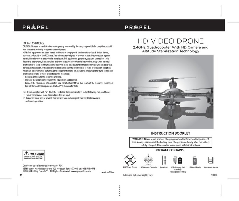
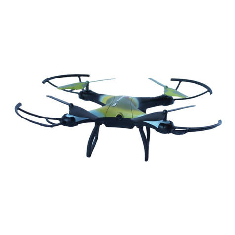
Aerpro APHUB X4 User manual

Read the User Manual and its instructions carefully before use!
14+
《User Manual Version 1.0》
APHUB
X4
REAL TIME FPV
Users may download the User Manual from the official AERPRO website.
WWW.AERPRODRONE.COM

02
Important safety information
Flight: Please be mindful of personal safety and the safety of others while flying.
Read the Disclaimer first before use.
launaMresUAPHUBX4
Please fly the APHUBX4 in accordance with the directions given in this <User Manual>.
Reading Tips
Symbol explanation
Prohibited Operation Important Notice Instruction Explanation/Reference
Operation: Be extremely careful and responsible when using the quad. Small electronic components can be
damaged due to crashes or exposure to moisture/liquid. To avoid any injuries, do not use the quad with broken or
damaged components.
Maintenance: Do not try to open or repair the units by yourself. Please contact AERPRO technical support
for service. For more information, please visit the official website at www.aerpro-drones.com.
Battery: Do not disassemble, squeeze, impact, burn, drop or trample the battery. Do not short-circuit or put the
battery terminal in contact with metal.
Do not expose the battery to temperatures above 60 ° C.
Charge the aircraft battery prior to flight. Use a Hubsan dedicated charger for charging. Keep the battery out of the
reach of children and away from any kind of moisture.
Do not fly the quad in crowded areas and always be aware of the safety of yourself and others.
Do not fly in bad weather conditions.
Do not attempt to catch the aircraft while it is in flight.
This product is intended for experienced pilots over the age of 14.
Keep your body away from the propellers after powered on. High speed propellers are very dangerous.
After every flight, completely disarm the aircraft motors and disconnect the aircraft from power. Then, you
may power off the remote control. Do not do so before at least disarming the aircraft motors! if the aircraft’s
motors are still running when you shut the remote control, the aircraft may engage its failsafe and attempt a
Return to Home.

03
Table of Contents
Important safety information
Reading Tips
Symbol Explanation
Usage Advice
Table of Contents
The APHUDX4 (H109S Standard) Profile
1 What’s Included
2 Aircraft Overview
Pre-Flight Checklist
1 The Aircraft Battery
1.1Introduction
1.2 Battery installation
1.3 Charging the Battery
2 Preparing the Aircraft
2.1 Introduction
2.2 The Camera
2.3 The 1-axis Gimbal
3 The Propellers
3.1 Introduction
3.2 Installation
3.3 Removal
3.4 Installing the Propeller Guards
4 Installing the Aircraft’s 5.8GHz
transmission antenna
5 The Remote Control/
Transmitter
5.1 Introduction
5.2 Getting to know the transmitter
5.3 Key functions
02
02
02
04
03
05
06
06
07
07
09
09
12
13
13
14
14
15
15
15
16
17
5.4 Battery installation
5.5 Transmitter stick calibration
5.6 Antennas
5.7 How to set or change the
5.8GHz video frequency
5.8 Binding the transmitter
and aircraft
Getting Ready to Fly
6 Compass Calibration
6.1 Compass Calibration
6.2 Horizontal Calibration
6.3 Rotational Calibration
18
18
19
19
20
21
21
22
22
7 Arming/Disarming the motors
8 Basic Flight Operation
9 Advanced performance set up
10 The Fail safes
10.1 Low power
10.2 Loss of flight control
connection
10.3 Conditions that would
trigger a failsafe
Frequently Asked Questions
23
23
25
27
27
27
27
28
Technical assistance 29
Features & Specifications 30
Laws for drone flight (AUS) 31
Laws for drone flight (NZ) 32

The APHUDX4 (H109S Standard) Profile
1 What’s Included
Please check all items in the box before use.
8Protection guard Protects the propellers
(includes 4 guards, 4 screws)
4
S/N Name Illustration Qty Description
1 Quadcopter 1 H109S Aircraft
4 x Propeller A, 4 x Propeller B2 Propellers
The 1-Axis Gimbal
4
3 1
4 Propeller wrench 1
5 Transmitter 1 The remote control (batteries not
included)
A single axis gimbal
Used to install and remove propellers
7 11.1V LiPo battery 1The aircraft battery
6 AC power adapter 1 A 110-240v adapter
9 Transmitter sunshield Reduces glare from the remote
video screen
1
The APHUDX4 is a four-rotor quadcopter made for aerial photography and filmography. It comes equipped
with a high-precision single-axis gimbal, 1080P HD camera and an advanced flight control system. The FPV remote
control is capable of long-range flight while supplying real-time video transmission FPV. The APHUDX4 can also
record video footage and take quality photos during flight.
ehtylfylevitiutniyamsresu,VPFhtiW.evitcepsrepnosrep-tsrifro,weiVnosrePtsriFsanwonkoslA:VPF
aircraft and enjoy an immersive flight experience.
04

11 Micro-USB camera cable
12
13 1080P Camera
User Manual
An HD camera
The transmitter’s 2.4GHz
transmission antenna
Used to read camera data; also
used to charge the camera battery
The Hubsan X4 PRO User Manual
14 2.4GHz transmission antenna 1
The aircraft’s 5.8GHz
transmission antenna
15 5.8GHz transmission antenna 1
1
1
1
10 Balance Charger Used to charge the aircraft battery
1
16 5.8GHz receiving antenna The transmitter’s 5.8GHz
receiving antenna
1
05
2 Aircraft Overview
Transmission system features External aircraft features Aircraft flight modes
Bidirectional data transmission
FPV/Video transmission
The 1-axis gimbal
The camera
Protection guard
Altitude Hold mode
GPS Hold mode
(aka the GPS position
Return to Home mode
hold feature)
Headless mode
Propeller Motor
The 1-axis gimbal
The 1080P Camera
Battery compartment
Landing gear
Landing gear pad (slippage prevention)
Compass
LED
The APHUDX4 comprises the aircraft, its camera, gimbal, propeller guards, power system, flight control
system and transmission system (remote control). The flight control system is built into the aircraft itself.

06
The transmitter
(uses 8 AA batteries or a
LiPo battery- not included)
Pre-Flight Checklist
1 The Aircraft Battery
Before using the APHUDX4, please verify that the battery is sufficiently charged.
Device Power supply
Transmitter 8 AA Batteries or a LiPo (2 or 3 cell)
3.7V 650mAh rechargeable LiPo battery (included)Camera
Aircraft (including the gimbal) The 11.1v 7000mAh aircraft battery powers both aircraft
and gimbal
The following is an overview of how to use and charge the aircraft battery.
1.1 Introduction
Please refer to the following installation and preparation steps before using the aircraft.
Battery specifications
hAm0007V1.11yticapaCType: Li-Po battery
Ambient temperature for charging 0°C~40°C Ambient temperature for use - 20°C~50°C
Environmental humidity for charging and use <80%
Before flight, check that the remote control and aircraft have sufficient power to fly.
Check the drone fuselage and propellers carefully. Broken or failed parts may cause dangerous malfunc-
tions.
Check that the battery is securely connected to the aircraft. Loose connections may be shaken by intense
flight and in-flight vibrations, which may lead to accidental disconnection and loss of power during use.
First power the transmitter on, then the aircraft. After use, first disconnect the aircraft from its battery- then
power off the transmitter. Incorrect operations preflight and inflight may cause flight malfunction, failure and
damage.
The quadcopter battery is a rechargeable Li-Po battery rated at 11.1V and has a 7000mAh capacity. Be
sure to use a Hubsan dedicated charger for charging. Fully charge the battery before flight.

12.3V
301°
A l t i t u d e M o d e
R o t a t e A i r c r a f t i n L e v e l
C a l i b r a t e C o m p a s s 1
7.3V
2°
-
-
07
Aircraft power level
Transmitter power level
1.2 Battery installation and use
Power on
Power on/power off
Checking power levels
1.3 Charging the Battery
Power on: Push the battery into its compartment and connect the bullet adapters as shown in the below
figure. Note the positive and negative polarities. The aircraft’s LEDs should light up.
Power off: Disconnect the battery adapters to power off the aircraft.
If the drone and transmitter are successfully paired, users may view power levels for both the transmitter
and drone on the remote control screen.
1) Connect the balance charger to the AC power adapter (100-240 V, 50/60Hz; if necessary, use a power conversion
plug). The balance charger LEDs will flash green, indicating th at it is on standby (as shown below).
(2) Remove the battery from the aircraft and connect the battery to the balance charger.
(3) The charger LEDs will turn a solid red to indicate charging in process.
(4) When the balance charger LEDs turn solid green, charging is complete. Please remove the battery from the
charger.
+
-

08
Safety Advisory Notice for Lithium-Polymer (LIPO) Batteries
1. Do not disassemble or reassemble the battery.
2. Do not short-circuit the battery.
3. Do not use or charge near sources of heat.
4. Do not put the battery in contact with water or any kind of liquid.
5. Do not expose the battery to direct fire or sunlight.
6. Do not puncture or subject the battery to force of any kind.
7. Do not throw or manhandle the battery.
8. Never charge a battery that has been damaged, become deformed or swelled.
9. Do not solder on or near the battery.
10. Do not overcharge or over discharge the battery.
11. Do not reverse charge or reverse the battery polarities.
12. Do not connect the battery to a car charger/cigarette lighter or any other kind of unconventional power
source.
13. This battery is prohibited for non-designated devices.
14. Do not touch any kind of liquid waste or byproduct from batteries. If skin or clothes come in contact with
these substances, please flush with water!
15. Do not mix other types of batteries with lithium batteries.
16. Do not exceed the specified charging time.
17. Do not place the battery in a microwave or in areas of high pressure.
18. Do not expose the battery to the sun.
19. Do not use in environments with high static electricity (64V and above).
20. Do not use or charge in temperatures below 0 and above 45 .
21. If a newly purchased battery is used, leaking, possesses a bad smell or any other abnormality, return
immediately to the vendor.
22. Keep away from the reach of children.
23. Use a dedicated battery charger and follow all charging requirements.
24. Minors who use the battery and its dedicated unit must be supervised by an adult at all times.
LiPo batteries are different from conventional batteries in that their chemical contents are encased in a relatively
lightweight foil packaging. This has the advantage of significantly reducing their weight but it does make them
more susceptible to damage if roughly or inappropriately handled. As with all batteries, there is a risk of fire or
explosion if safety practices are ignored:
(1) Overcharge protection : When the battery voltage level reaches 12.8V, the battery will stop charging.
Excessive charging will seriously damage the battery.
(2) Over-discharge protection : When the battery voltage level reaches 8.4V, the battery will stop outputting
power. Excessive discharging will seriously damage the battery.
(3) Short-circuit protection : When the battery detects a short-circuit, it will stop outputting power to protect
itself.
battery 50% charged to maintain battery performance
and life.
d discharge related battery damage, do not prolong the
discharge time.
months.

09
2 Preparing the Aircraft
The APHUDX4 comprises four motors, a single-axis gimbal,1080P HD camera and an advanced flight control
system. The aircraft is equipped with data and video transmission capabilities for user-friendly flight.
2.1 Introduction
2.2 The Camera
2.1.1 Flight control system overview
The APHUDX4 is an aircraft with nimble handling and excellent stability. Its flight system features multiple
GPS features, two fail safes, low power warnings and other functions.
Install the camera battery and secure the camera to its gimbal. After powering on the aircraft, press the camera’s
power button to turn it on. Users may then use the transmitter ’s camera and video function keys to take pictures
and record video.
[1]
[3]
[4]
[5]
[6]
[7]
[8]
[9]
[10]
[11]
[2]
Flight control system components
[1] Propeller
[2] Motor
[3] LED
[4] Gimbal shock
absorbers
[5] The 1-axis gimbal
[6] The 1080P Camera
[7] Landing gear
[8] Compass
[9] Battery compartment
[10] Gimbal and battery
interface
[11] Landing gear pad
(slippage prevention)
The motherboard: Also known as the mind and heart of the aircraft, the motherboard connects and controls the aircraft’s
main functional hardware.
IMU : The aircraft uses the IMU (inertial measurement unit) to determine and control its position and height in the air and
on the ground.
GPS and compass : The GPS and compass direct aircraft positioning/navigation when GPS functions are in use.
The LEDs : These indicators signal the current status of the flight control system.

10
Camera specifications
Video resolution 1920*1080 HD
Recording frame rate 30FPS
Video format MOV
Video format
Resolution
Lens specifications
3 million pixels MJPG
2048 * 1536 pixels
1/3”
Lens viewing angle 170 degrees (MAX)
1.9W
Power consumption (standby) 1.33W
Ambient storage temperature - 40〜+125 degrees Celsius
Ambient storage humidity 30%-90%
Battery 3.7V 650mAh
Ambient operational temperature 10〜+70 degrees Celsius
Ambient operational humidity 30%〜80%
Power consumption (operational)
2.2.1 Camera function overview
2.2.2 The Micro-SD card slot
2.2.3 The Micro-USB camera cable
When the camera is powered on, users may connect the camera to a PC with the provided Micro-USB cable to
view pictures and videos if a Micro-SD is in use. The camera battery will be charging at the same time.
[ Power button ]
[ Video botton/
Recording button ][Camera lens]
[ LED Indicator ]
[Microphone ]
USB
Note: The H906A transmitter is also used for photography, video recording
and playback. For more information, refer to the “H906A key functions”
section on page 17.
Before using the APHUDX4 to take pictures or videos, please
insert the Micro-SD card into the card slot (as shown on the right) when
the camera is turned off.
·A Micro-SD is not provided with the APHUDX4 Users must
provide or purchase a Micro-SD that is class 4 or above (recommended
class 6) and possesses between 4-32GB of memory. Format the
Micro-SD to FAT32 before using it.
·Be sure to format the Micro-SD to FAT32 before use. Verify that the
allocation unit size is set to 32 kilobytes- or the camera will be unable to
register the Micro-SD.
Power on/off: Short press the Power button (<2 seconds) once to power
Video recording: Short press the record button (<2 seconds) once to start
recording video. Press the record button again to stop the recording.
Data reading / Charging

11
2.2.4 The Camera’s Status Indicator
When the camera is powered on, its status indicator will light up. Users may determine the camera’s status by
watching the indicator’s light patterns.
2.2.5 Installing the camera
If the camera is connected to a computer via the Micro-USB, the former must be powered on to copy videos and
pictures to the PC. If the camera is powered off, media cannot be transferred (only the battery will charge).
If the camera’s USB connection to the aircraft is disconnected, any video recordings will be terminated. Under
any other conditions (i.e. when the camera is connected to the computer, or when the camera is connected to the
aircraft but not recording), the camera will simply power off.
The camera may also charge if it is connected to the aircraft.
Camera status indicator Camera status
Solid blue (no red) Camera is on standby mode
Solid blue with a red light flashing every second Camera is recording video
Camera has encountered a failure or malfunction
Solid blue and solid red
Blue light (no red) flashing every second Micro-SD is full/no card sensed in the camera/there is a
problem with the Micro-SD in use
Blue light (no red) flashing rapidly
Red light (no blue) flashing rapidly
Micro-SD is full
Low power (battery)
3
1. Unscrew the camera fixture frame from its position on the camera gimbal.
2. Install the camera facing outwards and refasten the camera fixture frame with its provided screws.
3. Plug the FPV transmission cable’s Micro-USB end into the camera’s Micro-USB socket. Insert the
cable’s other end to the input board on the belly of the aircraft.
Connects to the gimbal
and camera interface on
the belly of the aircraft.

12
2.3 The 1-axis gimbal
After the gimbal and camera are installed and the aircraft powered on, the gimbal will also power on and test
itself for issues. The gimbal’s movement (pitch) may be controlled by the H906A transmitter/remote control.
Gimbal features
Precision of control ±0.03 °
Range of motion Pitch: + 80 ° to -50 °
Stability features Shock absorbers+ software stabilization
2.3.1 Installing the 1-axis gimbal
(Gimbal installation diagram)
2Gimba l signal transmission line
3Camera FPV transmission cable
2.3.2 Checking gimbal operation and handling
1
2
3
32
ehtfoyllebehthtiwemarfs’labmigehtngila,tfarcriaehtforaerehtgnicafaremacehtfokcabehthtiW)1
aircraft. Slide the gimbal horizontally onto the drone.
erugifehtninwohssaecafretniaremacdnalabmigehtotenilnoissimsnartlangiss’labmigehtgulP)2
below.
saelbacnoissimsnartlangiss’labmigehtfotfelehtotelbacnoissimsnartVPFs’aremacehtgulP)3
shown in the figure below.
The gimbal signal line should be inserted with brown wire matching the negative polarity. If the gimbal
does not move after every line has been plugged in, please check to see if the gimbal line has been installed
backwards.
Anomalies in the gimbal’s movement may manifest if the aircraft is placed on uneven ground/grass
and the gimbal runs into foreign objects present. This may also happen if the gimbal experiences
excessive external movement/force (being hit or broken). Please make sure the aircraft is on flat, open
ground before taking off; do not move or disturb the gimbal while taking off.
Flying in fog or in cloud cover will most likely cause condensation on the gimbal and camera. If this
occurs, simply wipe the units dry with a soft cloth.

· The propellers are self-tightening units. Please do not use other screws or screw glue to attach them to the motor shafts.
· Make sure that the propellers are installed in the correct positions, otherwise the aircraft will not be able to fly
normally.
· Since the propeller blades are thin and somewhat sharp, it is recommended that users wear gloves during
installation to prevent accidental scratches.
13
3 The Propellers
3.1 Introducti on
Propeller Propeller A Propeller B
Illustration
Installation Use only with an “A” motor Use only with an “B” motor
Symbol explanation Lock: symbolizes the direction in which the propeller is tightened.
Unlock: symbolizes the direction which the propeller is loosened.
3.2 Installation
1) Before installing the propellers, please check to make sure that all letters on the propellers match the
letters on the motor arms. Propeller A’s go with A motors and propellers B’s go with B motors.
2) Mount all 4 propellers on their motors (A to A motors, B to B motors). Turn each propeller in the indicated
“lock” direction. Propellers should be firmly (but not overly) secured to their motor shafts.
The APHUDX4 uses 9-inch propellers. Each is marked with either an A or a B. Please replace damaged
propellers. Before installing the propellers for the first time, please check whether the propeller and
motor arm read "A" or "B”. The two letters should match.

14
3.3 Removal
When the blade is damaged or needs to be
replaced, hold the propeller with a hand or
the provided auxiliary wrench, and remove
by turning it in the indicated “unlock” direction.
3.4 Installing the Propeller Guards
It is recommended that beginners use the APHUDX4 propeller guards for flight safety while flying.
1
before each flight.
Before each flight, be sure to check that all propellers are free of deformations and undamaged. If any
propeller is damaged, please replace before flying.
performance.
• Remove the existing fuselage screws first. Use the longer propeller guard screws provided to then install the propeller
guards. (Note: The propeller guard screws and assembly/disassembly tools needed are located in the box housing the
guards themselves.)
• Please note the distinction between A propeller guards and B propeller guards during installation. Guards must be
matched with the appropriate motors (A to A, B to B), or installation will be impossible.

5 The Remote Control/Transmitter
15
5.1 Introduction
5.1.1 Main interface
4 Installing the Aircraft’s 5.8GHz transmission antenna
01
02
Screw the antenna onto
the aircraft by turning clockwise
Point the antenna
directly downwards
12.3V
301°
A l t i t u d e M o d e
R o t a t e A i r c r a f t i n L e v e l
C a l i b r a t e C o m p a s s 1
7.3V
2°
-
-
Aircraft Power/Voltage
Heading
Roll
Pitch
Speed
Distance
Altitude
Aircraft GPS Satellites
Remote Control GPS Satellites GPS coordinates
Remote control
power/voltage
Remove the antenna from its wrappings and locate the gold SMA connector at the side of the unit. Attach the
antenna to the connector by screwing it on clockwise. After securely tightening the antenna, bend it at the joint
to point it downwards.

16
(MODE 1)
5.2 GETTING TO KNOW THE TRANSMITTER
7 Power SW
4 Elevator Trim
(2) Elevator/Rudder Stick
5 Rudder Trim
UP Function
EXT Function Key
LCD
5.8GHz Antenna
9 Antenna
8 Neck Strap Eyelet
6 Throttle Trim
(1) Throttle /Aileron stick
3 Aileron Trim
ENT Function Key
Down Function
(MODE 2)
7 Power SW
6 Throttle Trim
1 Throttle /Rudder Stick
5 Rudder Trim
UP Function
EXT Function Key
LCD
SA
GPS
5.8GHz Antenna
9 Antenna
8 Neck Strap Eyelet
4 Elevator Trim
2 Elevator/Aileron stick
3 Aileron Trim
ENT Function Key
Down Function
T1 T2
Home
SB
SA
GPS
T1 T2
Home
SB
Video glasses socket
USB
Socket

T2 Rotary Switch controls the pitch rotation of the gimbal.
EXT Function Key
ENT Function Key
(1) Throttle /Aileron stick
Forward and backward movement of the stick will make the X4 Pro
increase or decrease speed respectively.Left and right movement
of the stick makes the X4 Pro roll left/right to initiate a turn.
(2) Elevator/Rudder Stick
Forward and backward movement of the stick makes the X4 Pro
nose point up/down respectively. Left and right movement of the
stick makes the X4 Pro yaw left/right respectively.
3 Aileron Trim Aileron trim adjusts left and right roll.
4 Elevator Trim Elevator trim adjusts up and down movement.
5 Rudder Trim Rudder trim adjusts left and right yaw.
6 Throttle Trim Throttle trim adjusts speed of motor.
7 Power SW Pushing the switch up powers on the transmitter, pulling it down
switches it off.
8 Neck Strap Eyelet For the attachment of a neck strap which eases the tension of your
hands from holding the transmitter.
9
10
13
14
Antenna
SA
Transmits the 2.4Ghz wireless signal.
Push: Headless Function
Pull down: Normal Function
11
T2
No function for now.
12 GPS Push: Altitude mode and Position Mode
Pull down: Exit the Altitude Mode and Position Mode
Home
T1/ SB
Push: Enter the RTH function.
Pull down: Exit the RTH function.
15
16
17
USB Socket Only for engineer to upgrade the software, please do not use it to
connect computer.
Exit settings; Shoot videos/ take photos/ play back when in camera mode.
Enter settings; Controls the camera mode: shoot videos, take photos,
play back videos/photos.
S/N IDENTIFICATION FUNCTION
1
Throttle/Rudder Stick
2
Elevator/Aileron Stick
Forward and backward movement of the stick makes the X4 Pro nose
point up/down respectively. Left and right movement of the stick
makes the X4 Pro roll left/right to initiate a turn.
Forward and backward movement of the stick will make the X4 Pro
increase or decrease speed respectively.Left and right movement of the
stick makes the X4 Pro yaw left/right respectively.
17
5.3 KEY FUNCTIONS

18
Do not mix new and old batteries Do not use a discharged battery
Do not cross-use different types of batteries at the same time
A A A A
A A A A
A A A A
5.4 Battery installation
A A A A
5.5 Transmitter stick calibration
Open the compartment hatch
and remove the battery pack.
Plug the battery pack back into
the compartment. Close the
compartment hatch and screw
it shut.
Insert 8 AA batteries into the
slots of the battery pack. Take
note to make sure the polarities
are correctly matched.
Mode 1: Push the left stick to the upper left corner and the right stick to the upper right corner. Power the
transmitter on while holding both sticks in their respective positions; the LCD screen will show “Calibrate
Sticks Mode 2”. Let go of the sticks, then pull them up, down, towards the center and outwards. Repeat this
sequence 3 times, then release both sticks and hold the “Exit” key until the transmitter beeps. This indicates
a successful calibration.
Mode 2: Push both sticks to the upper left corners. Power the transmitter on while holding both sticks in their
respective positions; the LCD screen will show “Calibrate Sticks Mode 2”. Let go of the sticks, then pull them
up, down, towards the center and outwards. Repeat this sequence 3 times, then release both sticks and hold
the “Exit” key until the transmitter beeps. This indicates a successful calibration.

19
5.7 How to set or change the 5.8GHz video frequency
5.6 Antennas
S e t r e v e r s e +
S e t s e n s i t i v e +
M a n u a l m o d e O F F
E x p e r t m o d e Y E S
S t i c k m o d e 1
5 . 8 G f r e q u e n c e
F l y w h e n n o G P S N O
S h o w V e r s i o n
7.2V
12.2V
>
Failure to keep the antenna’s logo unobstructed and pointing towards the aircraft may lead to
poor video transmission.
The transmitter will automatically find the best frequency to ensure a good quality live video. If desired or
needed, users may manually search the 5.725-5.945GHz frequencies for a better video transmission signal.
To adjust the 5.8GHz frequency, first pull and hold the throttle stick downwards to the very bottom of its socket.
While doing so, long press the "Enter" key to enter the Main Menu. Use the Up/Down keys and scroll to the
“5.8G frequence” selection. Press "Enter" to enter the frequency menu; use the Up and Down keys to browse
the different frequencies. Long press the "Exit" key for 2 seconds to save the new frequency setting and exit.
To keep video transmission clear and avoid interference, make sure the H906A’s 5.8Ghz antenna logo
faces the aircraft. During flight, the antenna and its signal path must be unobstructed to maximize the
video and control range. Bend the antenna so that its logo is as directly pointed towards the aircraft as
possible.

20
5.8 Binding the transmitter and aircraft
Getting ready to fly
Pre-Flight checklist
High pressure lines Rain
Magnetic interferenceAirports
Flight environment requirements
B i n d t o P l a n e
7.1V
It is recommended that users implement some kind of flight training (i.e using a simulator for flight practice,
seeking professional guidance, etc.) before flying the H109S. Please select an appropriate flight environment
for flight.
(1) Select an open environment devoid of high rise buildings and tall obstructions (such as trees and poles).
Near buildings and obstacles, flight control signals and GPS signals can be severely weakened; GPS
functions such as GPS mode and Return to Home may not function properly.
(2) Do not fly in bad weather conditions (such as in wind, rain, fog, etc).
(3) When flying, please stay away from obstructions, crowds, high voltage lines, trees, water, etc.
(4) To avoid remote control signals interference, do not fly in complex electromagnetic environments (such as
venues with radio stations, power plants and towers).
(5) The APHUDX4 cannot be used in or near the Arctic circle or Antarctica.
(6) Do not fly in restricted areas or no-fly zones.
(7) Do not operate the aircraft near high pressure lines, airports or areas with severe magnetic interference.
1) Make sure the aircraft battery and mobile device are charged and have adequate power.
2) Confirm that propellers are properly installed.
3) Check that the gimbal is properly installed and that all lines are inserted into the correct sockets.
4) If one is taking pictures, insert the Micro-SD card required for taking pictures and videos.
5) After powering on the aircraft and transmitter, see that the gimbal and camera are operating normally.
6) Verify that the motors arm and spin smoothly.
Only use this process if the aircraft and transmitter are not pairing automatically when powered on, or to reset
the 2.4GHz flight control and 5.8GHz video transmission connections! The binding process is usually
completed in the factory. If you replace either the remote or the aircraft, the two will need to be re-bound to
each other.
1) Hold the "Enter" key and power on the transmitter until
“System Initialize" appears on the LCD screen.
2) Release the Enter key when the screen changes to display
“Bind to Plane”.
3) Power on the quad and place it very close to the transmit-
ter. After a few seconds, the transmitter should then beep,
indicating that binding has been successful.
4) If this does not happen and the aircraft’s LEDs begin to
rotate clockwise, the binding is unsuccessful. Please power
off the quad and repeat the above steps.
Table of contents
