Aerpro AERA10D User manual
AERA10D
Copyright © 2022
10" MULTIMEDIA RECEIVER
MODEL NUMBER: AERA10D
INSTALLATION GUIDE
aerpro.com

Installation of this product requires technical skill
and experience. It is recommended to have it
professionally installed by an authorized
Aerpro/Connects2 Dealer.
Read entire instructions thoroughly before starting.
Disconnect the vehicle's negative battery cable
before making any wire connections.
Protect all vehicle surfaces with tape or plastic
Do not install components in any location that will
hinder vehicle operation, such as steering wheel,
gearshift, air bags, hazard switch.
All wiring should be secured away from sharp
edges and moving parts.
PRECAUTIONS
AGREEMENT: End user agrees to use this product in compliance with the instructions and terms of use and with all
State and Federal laws. AERPRO provides instructions and safety warnings with respect to this product and disclaims
all liability for any use not in conjunction with those instructions or other misuse of its product. If you do not agree,
please discontinue use and contact AERPRO. This product is intended for off-road use and passenger use only.
TECHNICAL ASSISTANCE:
If you need assistance setting up or using your Aerpro product now or in the future, call Aerpro
Support. Australia. Mon-Fri 9am – 5pm AEST
TEL: 03 – 8587 8898 FAX: 03 – 8587 8866
Visit aerpro.com for
User Guide | Install Guides | Updates | Tech Tips

CONTENTS
Contents.........................................................3
Parts List........................................................4
Hardware Guide.............................................5
Pre-Assembly...................................................6
Display Assembly.............................................7
Mounting Options..........................................7
Double DIN Dash Kit Mounting.......................8
Double DIN Sub-Dash Kit Mounting...............10
Double DIN Factory Bracket Mounting............12
Single DIN Dash Kit Mounting........................14
Final Assembly...............................................16
Wiring & Connections....................................17
Dimensions....................................................21
Troubleshooting..............................................22
Upgrades/Options.........................................23
INSTALLATION GUIDE

4
Parts List
QTY DESCRIPTION
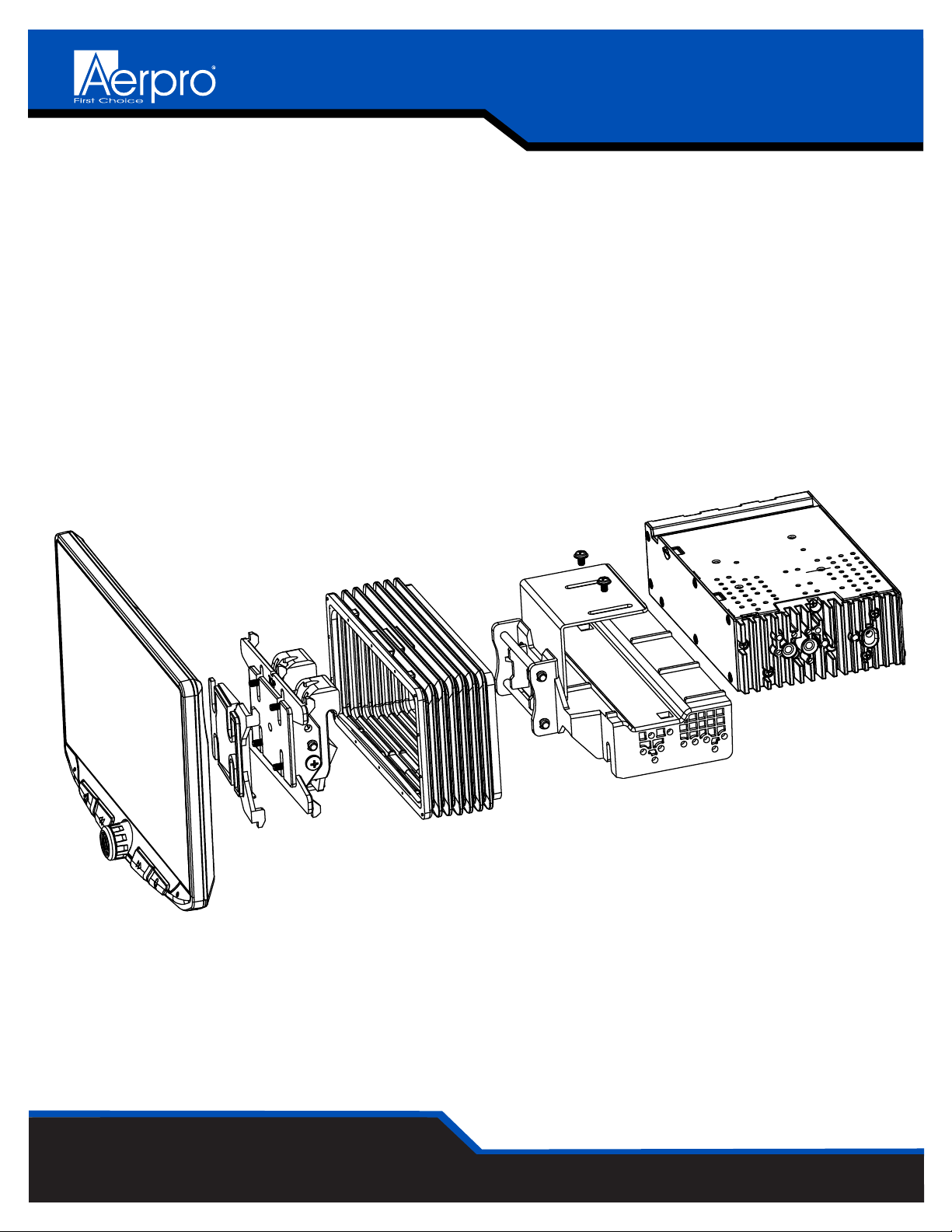
1 Touch Panel Display
1 Radio Module
Mounting Brackets / Hardware
1 Plastic Dash Mounting Bracket
1 Display Mounting Clamp
1 Metal Mounting Bracket
1 Horizontal Display Angle Plate
1 Rubber Boot
4 M4 X 6 Screw
4 M4 X 10 Screw
4 M4 X 12 Screw
2 M4 X 14 Screw
2 M4 x 18 Screw
6 M5 x 10 Screw
6 #10 x 3/8 Screw
2 Backstrap
Cables / Harnesses
1 8 Pin Display Power Harness - 18in
1 LVDS Display Video Cable - 18in
1 16 Pin Power / Speaker Harness
1 24 Pin AV / Rear Camera Harness
1 10 Pin Multi Camera Harness
1 6 Pin SWI / IR Harness
1 4 Pin Mic / Camera Audio Harness
1 External Microphone
1 GPS Antenna & Mounting Plate
5
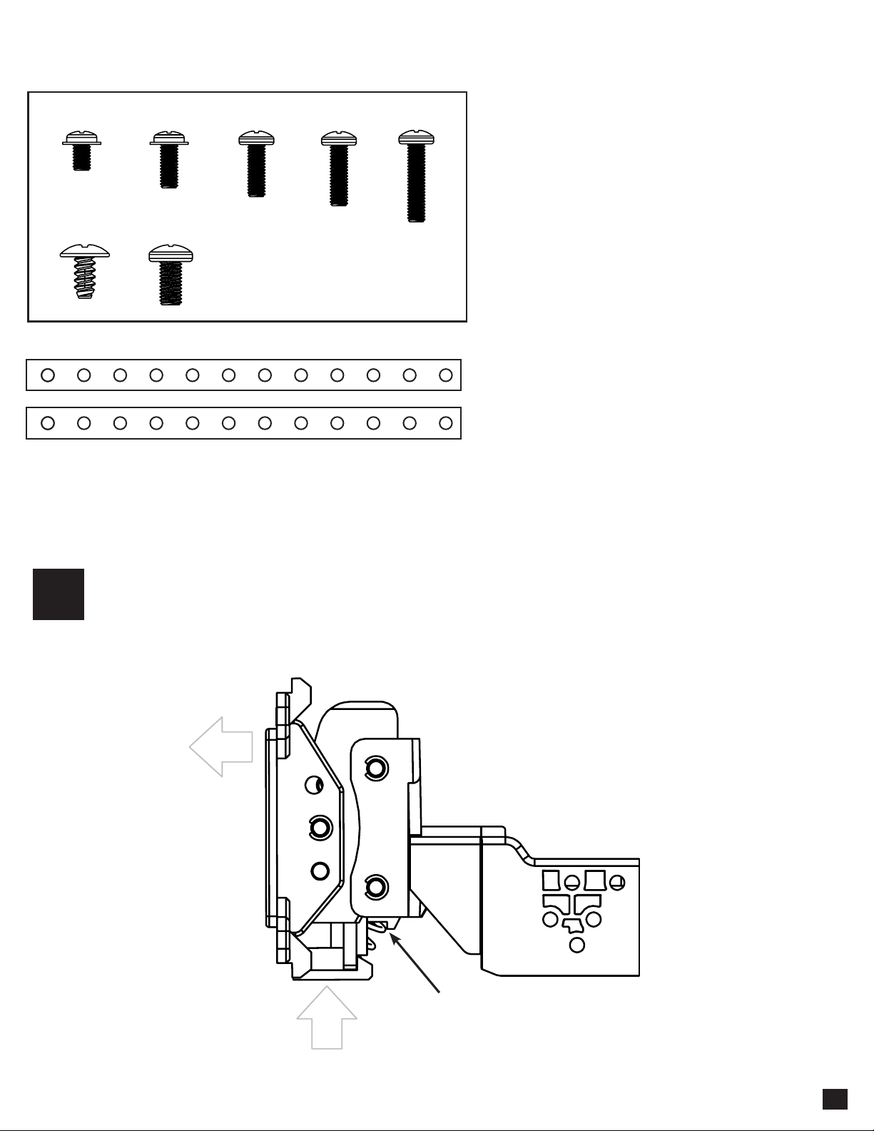
M4 X 6 M4 X 10 M4 X 12 M4 X 14 M4 X 18
#10 X 3/8 M5 X 10
NOTE: Depending on the
installation, not all screws
will be used.
Hardware Guide
Note: The 2 Backstrap (SE-1003) can be used in some applications to add additional support or used in custom installations.
The backstrap may mount to the sides of the radio chassis using the provided screws in the existing mounting locations or can
be mounted directly to the Plastic Dash Mounting Bracket.
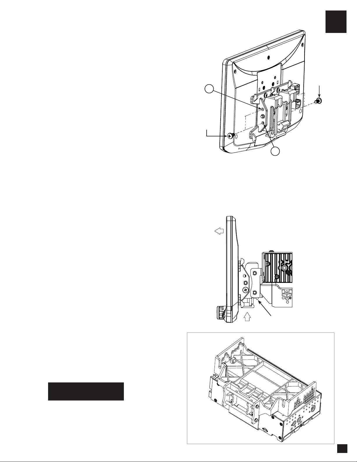
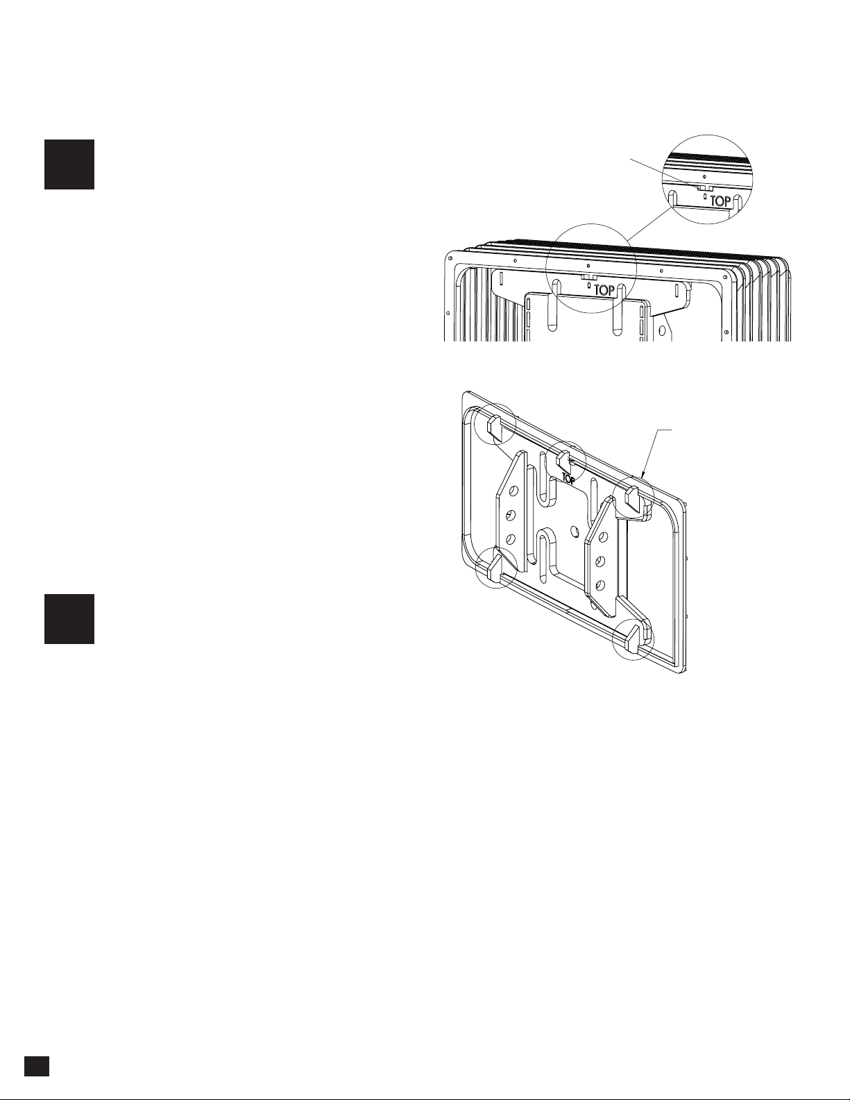
Remove the clamp assembly from the plastic mounting bracket by pushing up from
compression spring side (1) and swing out to unhook top (2).
1
1
2
Compression Spring
6
Single DIN Applications: For Single DIN
installations, the Plastic Dash Mounting
Bracket will be mounted in the dash kit
the dash kit and the Radio Module will be
mounted remotely. Before beginning the
installation, determine where the Radio
Module will be installed and make sure
the Display Cables are long enough.
Longer, 1.5 Metre cables are available
(SE-1501 & SE-1502).
Plastic Dash
Mounting Bracket
Single DIN ISO Dash Kit
(Not Included)
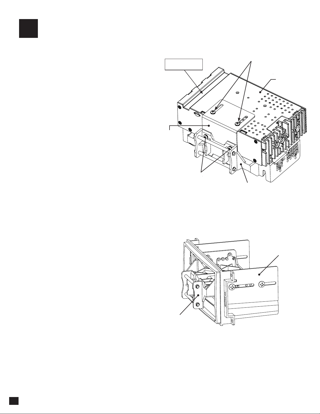
Double DIN Applications: Attach the Metal
Bracket to the Plastic Dash Mounting Bracket
using M4 X 6 screws. Attach metal bracket and
plastic dash mounting bracket assembly to the
Radio Module using M4 X 6 screws.
2
M4 X 6
M4 X 6
Metal
Bracket
Radio
Module
Plastic Dash
Mounting Bracket
Optional
Cable Channel
Pre-Assembly

7
4A
4B
4C
4D
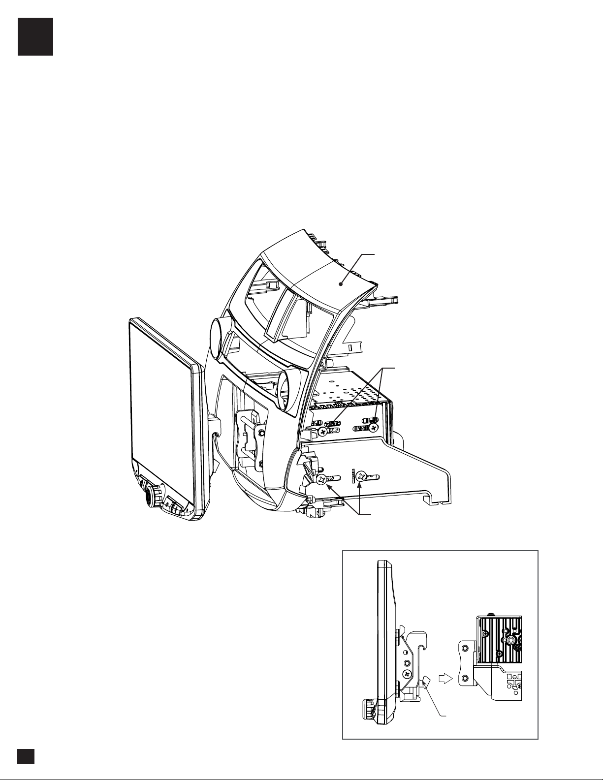
The display can be installed Flat or with a Horizontal Angle towards the driver. For flat mounting,
attach the Clamp Assembly (1) to the display using M4 X 14 screws (FIG. A). If a horizontal angle
is desired, insert the Angle Plate (2) in between the clamp and display and replace 2 of the M4 X
14 screws with longer M4 X 18 screws on the thicker side of the angle plate (FIG. B). Center the
bracket on the back of the display as a starting point, and if needed you can adjust up or down.
FIG. A FIG. B
2
1 1
3
TOP
M4 X 12
(4X)
M4 X 18
(2X)(4X)
M4 X 14
(2X)X)
No Horizontal Angle With Horizontal Angle
Display Assembly
Multiple Mounting Options
AERA10D can be configured for different mounting applications:
See Aerpro website for TECH TIPS on vehicle specific installations.
Using a Double DIN Dash Kit (PAGE 8)
Using a Double DIN Sub-Dash Kit (PAGE 10)
Using a Double DIN Factory Radio Mounting Brackets (PAGE 12)
Using a Single DIN ISO Mountable Dash Kit, relocating Radio Module (PAGE 14)
Custom Mounting Applications.
TOP
Always ensure TOP indicator on the Clamp Assembly is facing UP.
8
Using a Double DIN Dash Kit:
Radio chassis mounts to the brackets attached to the kit main frame
4A
1
2
HOOK BOTTOM
FIRST, THEN TOP
#10 X 3/8
Coarse Thread Screw
M5 X 10
AFTERMARKET
DASH KIT
(NOT INCLUDED)
NOTE: BOOTAND DASH KIT NOT SHOWN
FIG. D
FIG. C
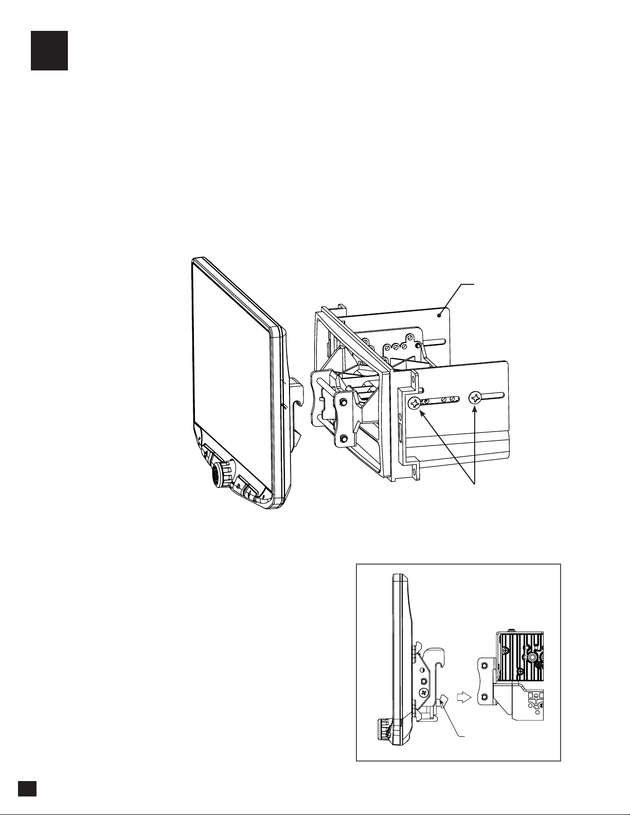
Display Adjustment & Mounting:
1. Install the dash kit side brackets to the main frame.
2. Making sure to use all 8 screws, loosely attach the radio module & mounting bracket assembly to the side
kit brackets (FIG. C).
a. (4x) #10 X 3/8 screws for the plastic mounting bracket locations
b. (4x) M5 X 10 or (4x) M4 X 10 screws for the radio module locations (use any combination of screws
to locate the radio in the best position)
3. Attach the display to the bracket assembly by
hooking bottom spring hook and then pushing up and
hooking top hooks. (FIG. D)
1
2
NOTE: BOOTAND DASH KIT NOT SHOWN
4A
FIG. E
FIG. G
FIG. F
9
4. Determine the desired position of the display:
a. Display can be vertical or tilted up (FIG. E)
b. Display can slide up or down (Page 7)
c. Display can be tilted horizontally (Page 7 – FIG. B)
Note: There are multiple mounting holes on
the mounting bracket to allow adjusting the
mounting depth. You may drill additional holes
in the mounting bracket and/or the dash kit
brackets to align the display in the best position
and ensure you can use all 8 mounting screws.
5. Once in the desired position, tighten screws
to the radio chassis (top) and mounting bracket
assembly (bottom).
Note: If the display prevents the factory dash
panel(s) from being installed last, do not push
the display all the way up against the dash
kit. Leave enough bottom gap as the display's
bottom edge rotates towards the dash kit.
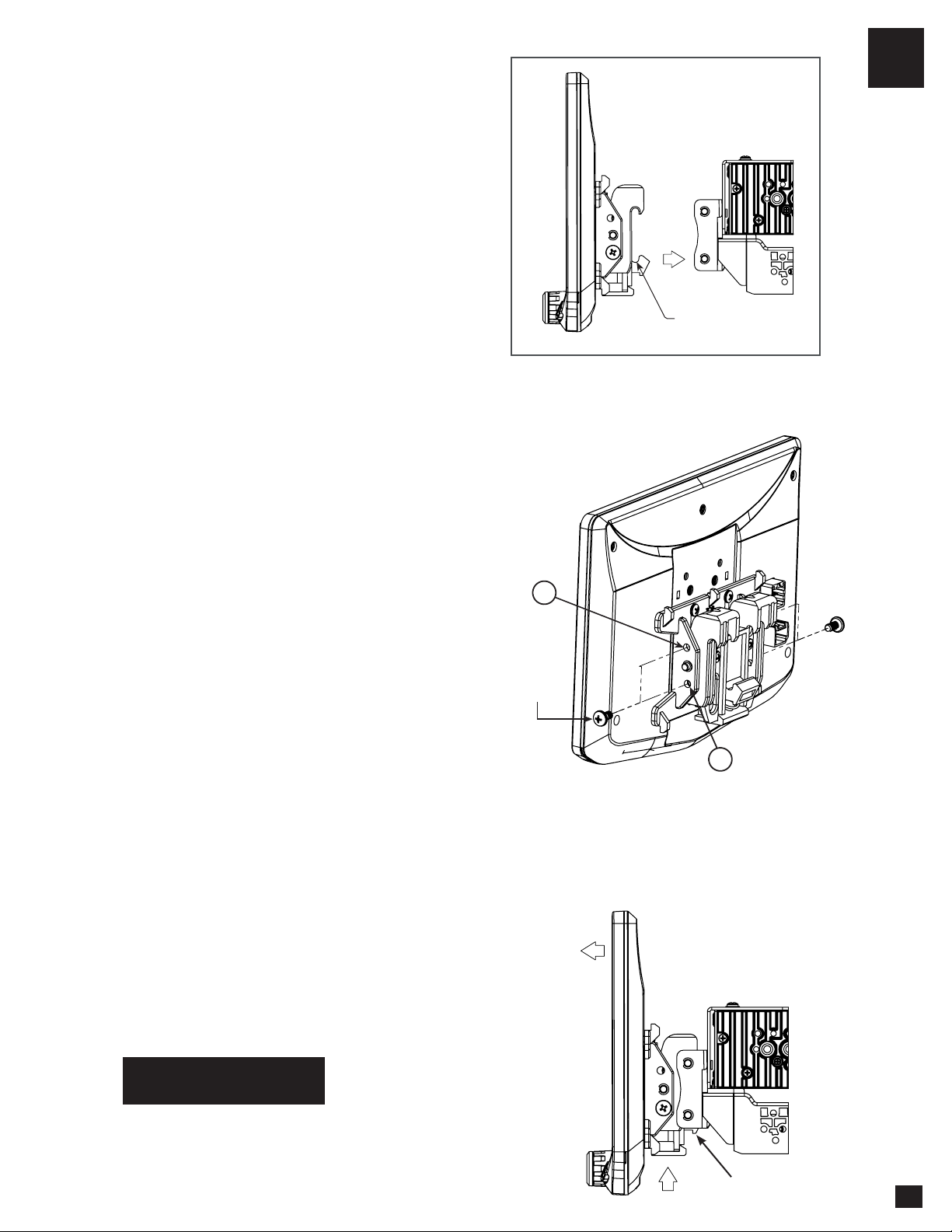
6. Remove the display from the bracket
assembly by pushing up from compression
spring side (1) and swing out to unhook top (2).
(FIG. F)
Note: If there is a depth issue with the radio
module in the top position, move it to the
bottom location by inverting the mounting
bracket assembly. (FIG. G)
VERTICAL TILT: Use Hole A for no vertical
tilt or Hole B for 8 degrees of vertical tilt.
Insert a M5 X 10 on each side of the clamp
assembly at desired tilt.
A
M5 X 10
M5 X 10
Compression Spring
PROCEED TO STEP 5
on Page 16
B

Using a Double DIN Dash Kit:
Radio chassis mounts to the kit brackets in the sub-dash, not to the kit main frame
4B
#10 X 3/8
Coarse Thread Screw
M5 X 10
AFTERMARKET
DASH KIT
(NOT INCLUDED)
FIG. H
FIG. I
Display Adjustment & Mounting:
1. Use all 8 kit mounting screws to attach the radio module & plastic mounting bracket assembly to the kit
brackets at the front most location (not to exceed the front of the kit bracket). (FIG. H)
a. (4x) #10 X 3/8 screws for the bottom locations
b. (4x) M5 X 10 or (4x) M4 X 10 screws for the radio module locations (use any combination of screws to
locate the radio in the best position)
Note: There are multiple mounting holes on the
plastic mounting bracket to allow adjustment of the
mounting depth. You may drill additional holes in
the mounting bracket and/or the dash kit brackets to
align the display in the best position and ensure you
can use all 8 mounting screws.
2. Install the assembly (from Step 1) into the vehicle
(using factory screws/bolts).
3. Install the dash kit main frame and any factory
panels that would affect the display installation.
Note: If there is a depth issue with the radio
module in the top position, move it to the bottom
location by inverting the mounting bracket
assembly. (FIG. I)
10

Using a Double DIN Dash Kit:
Radio chassis mounts to the kit brackets in the sub-dash, not to the kit main frame 4B
FIG. K
5. Determine the desired position of the display:
a. Display can be vertical or tilted up (FIG. K)
b. Display can slide up or down (Page 7)
c. Display can be tilted horizontally (Page 7 – FIG. B)
6. Determine the final front to back position by
measuring the shortest distance between the
display to the dash kit main frame or the factory
dash and subtract that distance/measurement by
~6.35mm
Note: Do not push the display all the way up
against the dash. Leave enough bottom gap as
the display's bottom edge rotates towards the
dash.
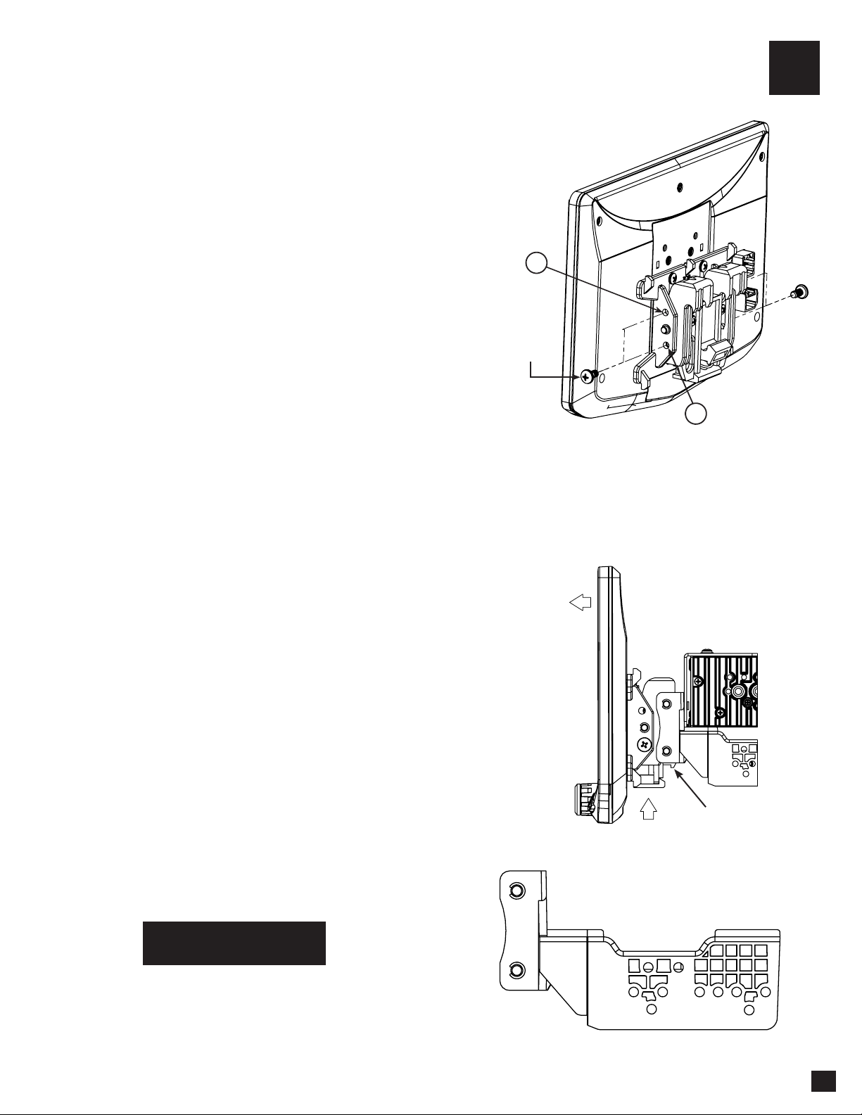
7. Remove the display from the bracket
assembly by pushing up from compression
spring side (1) and swing out to unhook top (2).
(FIG. L)
8. Remove the radio module & mounting
bracket assembly from the vehicle. Using the
measurement taken in step 6, slide the radio
module & bracket assembly back to that
distance.
FIG. J
4. Attach the display to the mounting bracket
assembly by hooking bottom spring hook and
then pushing up and hooking top hooks. (FIG. J)
11
PROCEED TO STEP 5
on Page 16
1
2
HOOK BOTTOM
FIRST, THEN TOP
NOTE: BOOTAND DASH KIT NOT SHOWN
VERTICAL TILT: Use Hole A for no vertical
tilt or Hole B for 8 degrees of vertical tilt.
Insert a M5 X 10 on each side of the clamp
assembly at desired tilt.
A
M5 X 10
M5 X 10
B
1
2
FIG. L
Compression Spring

12
Using Factory Radio Brackets:
Radio chassis mounts to the factory brackets in the sub-dash
4C
FIG. M
FIG. N
Factory Bracket
M5 X 10
#10 X 3/8
Coarse Thread Screw
New holes in the factory brackets may need
to be drilled for optimal screen position
Display Adjustment & Mounting:
1. Use all 8 kit mounting screws to attach the radio module & plastic mounting bracket assembly to the
factory brackets. (FIG. M)
a. (4x) #10 X 3/8 screws for the bottom locations
b. (4x) M5 X 10 or (4x) M4 X 10 screws for the top locations (radio module).
If factory bracket is thinner than 1mm, add a washer to space the screws out.
Note: There are multiple mounting holes on the
plastic mounting bracket to allow adjusting the
mounting depth. You may drill additional holes in
the mounting bracket and/or the factory brackets
to align the display in the best position and
ensure you can use all 8 mounting screws.
2. Install the assembly (from Step 1) into the
vehicle (using factory screws/bolts).
3. Install the dash kit main frame and any factory
panels that would affect the display installation.
Note: If there is a depth issue with the radio
module in the top position, move it to the bottom
location by inverting the mounting bracket
assembly. (FIG. N)
M5 X 10
13
4C
5. Determine the desired position of the display:
a. Display can be vertical or tilted up (FIG. P)
b. Display can slide up or down (Page 7)
c. Display can be tilted horizontally (Page 7 – FIG. B)
6. Determine the final front to back position by
measuring the shortest distance between the
display to the dash kit main frame or the factory
dash and subtract that distance/measurement by
~6.35mm
Note: Do not push the display all the way up
against the dash. Leave enough bottom gap as
the display's bottom edge rotates towards the
dash.
7. Remove the display from the bracket
assembly by pushing up from compression
spring side (1) and swing out to unhook top (2).
(FIG. Q)
8. Remove the radio module & mounting
bracket assembly from the vehicle. Using
the measurement taken in step 6, install the
radio module & bracket assembly back to that
distance. (New holes in the factory brackets may
need to be drilled).
4. Attach the display to the mounting bracket
assembly by hooking bottom spring hook and
then pushing up and hooking top hooks. (FIG. O)
PROCEED TO STEP 5
on Page 16
FIG. P
FIG. O
1
2
HOOK BOTTOM
FIRST, THEN TOP
NOTE: BOOTAND DASH KIT NOT SHOWN
VERTICAL TILT: Use Hole A for no vertical
tilt or Hole B for 8 degrees of vertical tilt.
Insert a M5 X 10 on each side of the clamp
assembly at desired tilt.
A
M5 X 10
M5 X 10
B
1
2
FIG. Q
Compression Spring
Using a Single DIN ISO Mountable Dash Kit:
Radio chassis mounts separately into the sub-dash
4D
Display Adjustment & Mounting:
1. Install the dash kit brackets to the main frame.
2. Making sure to use 4 screws, loosely attach the plastic mounting bracket assembly to the side kit
brackets. (FIG. R)
a. (4x) #10 X 3/8 screws
AFTERMARKET
DASH KIT
(NOT INCLUDED)
#10 X 3/8
Coarse Thread Screw
3. Attach the display to the bracket assembly.
(FIG. S)
FIG. R
14
FIG. S
1
2
HOOK BOTTOM
FIRST, THEN TOP
NOTE: BOOTAND DASH KIT NOT SHOWN
4D
4. Determine the desired position of the display:
a. Display can be vertical or tilted up (FIG. T)
b. Display can slide up or down (Page 7)
C. Display can be tilted horizontally (Page 7 – FIG. B)
Note: There are multiple mounting holes on the mounting
bracket to allow adjusting the mounting depth. You may
drill additional holes in the mounting bracket and/or the
dash kit brackets to align the display in the best position
and ensure you can use 4 mounting screws.
5. Once in the desired position, tighten screws to the
mounting bracket assembly.
Note: If the display prevents the factory dash panel(s) from
being installed last, do not push the display all the way
up against the dash kit. Leave enough bottom gap as the
display's bottom edge rotates towards the dash kit.
6. Remove the display from the bracket assembly by
pushing up from compression spring side (1) and
swing out to unhook top (2).
(FIG. U)
Note: The plastic mounting bracket assembly may be
inverted to align the display in the best position. (FIG. V)
FIG. V
15
PROCEED TO STEP 5
on Page 16
NOTE: BOOTAND DASH KIT NOT SHOWN
FIG. T
VERTICAL TILT: Use Hole A for no vertical
tilt or Hole B for 8 degrees of vertical tilt.
Insert a M5 X 10 on each side of the clamp
assembly at desired tilt.
A
M5 X 10
M5 X 10
B
1
2
FIG. U
Compression Spring
16
If needed, attach the rubber boot to
the display clamp assembly by aligning
the notch on the top edge as shown,
and hook the boot to the clamp at 5
locations. (FIG. W)
Note: The boot is not required if display
sits very close to the dash/dash kit and
no large gap is seen.
BOOT ASSEMBLY PLASTIC "TAB"
HAS TO GO INTO A NOTCH
(DISPLAY UNIT NOT SHOWN)
BOOT ASSEMBLY HOOKS
AT 5 SPOTS
(RUBBER BOOT NOT SHOWN)
BOOT ASSEMBLY PLASTIC "TAB"
HAS TO GO INTO A NOTCH
(DISPLAY UNIT NOT SHOWN)
BOOT ASSEMBLY HOOKS
AT 5 SPOTS
(RUBBER BOOT NOT SHOWN)
After all wiring connections are made
in the next section, the dash kit with the
radio chassis and bracket assembly,
should be installed and any factory
panels reinstalled. Connect the 8 Pin
Display Power Harness and the LVDS
Video Cable to the back of the display
and attach display to mounting bracket.
5
6FIG. W
Final Assembly
Wiring and Connections
17
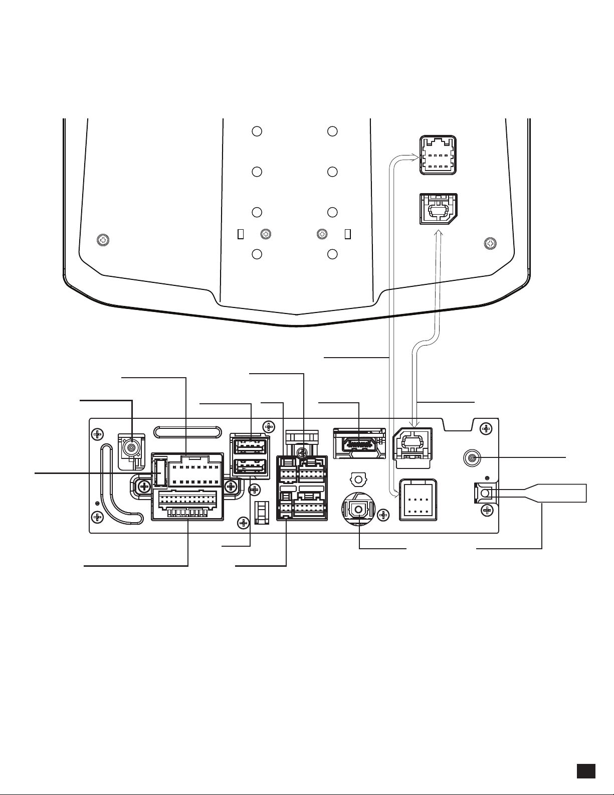
GPS Antenna must be installed for accurate
operation of Apple CarPlay, Android Auto &
internal Navigation.
1The top USB1 must be used for
Apple CarPlay and Android Auto.
Display Cable
Multi Camera
USB1 CP/AA1
Power / Speaker
GPS Antenna LVDS Cable
HDMI Input
USB2
SWI
AV In/Out - Rear Camera Microphone
Radio Antenna
TOSLINK
15 Amp Fuse
DAB Antenna

Connect radio power and speaker connections to a vehicle specific harness
(sold separately) referencing diagram below.
16 Pin Power / Speaker Harness
REAR L -
FRONT L -
FRONT L +
REAR L +
REAR R -
FRONT R -
FRONT R +
REAR R +
P. ANTENNA
P. CONTROL
REVERSE SW
PARKING SW
ACC
GND
BATTERY
ILLUMINATION
Connector View is pin side
18
Wiring and Connections
IN WIRING HARNESS
Purple Right Rear Speaker +
Purple/Black Right Rear Speaker -
Green Left Rear Speaker +
Green/Black Left Rear Speaker -
Grey Right Front Speaker +
Grey/Black Right Front Speaker -
White Left Front Speaker +
White/Black Left Front Speaker -
Yellow Permanent 12V +
Black Ground -
Red Ignition 12V +
Orange Illumination +
Blue Power Antenna +
Purple/White Reverse Gear +
Blue/White Power Control +
Light Green Park Brake +

Connector View is pin side
19
A1 Brown / Black SWC Key 2
A2 Brown SWC Key 1
A3 Black SWC Ground
A4 Yellow RCA Video Input
A5 White RCA Audio Input Left
A6 Red RCA Audio Input Right
A7 Yellow RCA Camera Input
A8 Yellow RCA Video Output 1
A9 Yellow RCA Video Output 2
A10 White RCA Zone 2 Left
A11 Red RCA Zone 2 Right
A12 Red RCA Right front
A13 White RCA Left Front
A14 Red RCA Right Rear
A15 White RCA Left Rear
A16 Brown RCA Left Subwoofer
A17 Blue RCA Right Subwoofer
Analog Steering
Wheel Control Input
Audio / Video Input
Video Output
Audio Output
24 Pin AV / Rear Camera Harness
Audio/Video Inputs & Outputs / Rear Camera Video Input / Resistive Steering Wheel Control Inputs
To program SWC, go to SETTINGS > Systems Settings > Installer Settings > Passcode:0052 >
Advanced Vehicle Settings > Steering Wheel Control. Do not use if using a PAC SWI Interface.
Wiring and Connections
4
4Video Outputs 1 and 2 are the same signal.
SWC KEY 2
SWC KEY 1
SWC GROUND
AUX IN
ZONE 2 AUDIO OUT
FRONT OUT
REAR OUT
SUB OUT
REVERSE CAMERA IN
VIDEO OUT 1
VIDEO OUT 2
A1
A2
A3
A4
A5
A6
A7
A8
A9
A10
A11
A12
A13
A14
A15
A16
A17
Red RCA
White RCA

SWI
EXTERNAL IR
ORANGE
BLACK
Steering Wheel Control Input
External IR input
6 Pin SWI / IR Harness
3.5mm Input for optional Steering Wheel Control Interface
(PAC Audio SWI-CP2 is recommended for full compatibility and advanced features. Visit PAC-Audio.com)
4 Pin Microphone / Camera Audio Harness
Input for External Microphone (included) used for hands-free calling, Apple CarPlay and Android
Auto / Optional reverse camera audio input
WHITE
REVERSE CAM AUDIO IN
MIC
BLACK
Microphone Input
Reverse Camera Audio Input
PAC Interface
CAMERA 2
CAMERA 3
CAMERA 4
CAM 3 [+] TRIGGER
CAM 4 [+] TRIGGER
CAM 2 [+] TRIGGER
SPEED SEN
PAC LINK
Front Camera Video Input
Right Camera Video Input
Left Camera Video Input
Pink - Vehicle Speed Sensor Input
White/Grey - Left Camera Trigger (+)
White/Purple - Front Camera Trigger (+)
White/Green - Right Camera Trigger (+)
10 Pin Multi Camera Harness
3 additional camera inputs and triggers / Vehicle Speed / PAC Link
Camera Triggers 2 & 3 will accept a pulsing + trigger (turn signal).
20
Wiring and Connections
Other manuals for AERA10D
2
Table of contents
Other Aerpro Receiver manuals


