8
Kitchen Faucet
Adapter
F
Inlet Water
Tube Connection
Manifold Outlet
for Faucet
A
RO System
Manifold
Kitchen Faucet
Adapter
F
Inlet Water
Tube Connection
Manifold Outlet
for Faucet
A
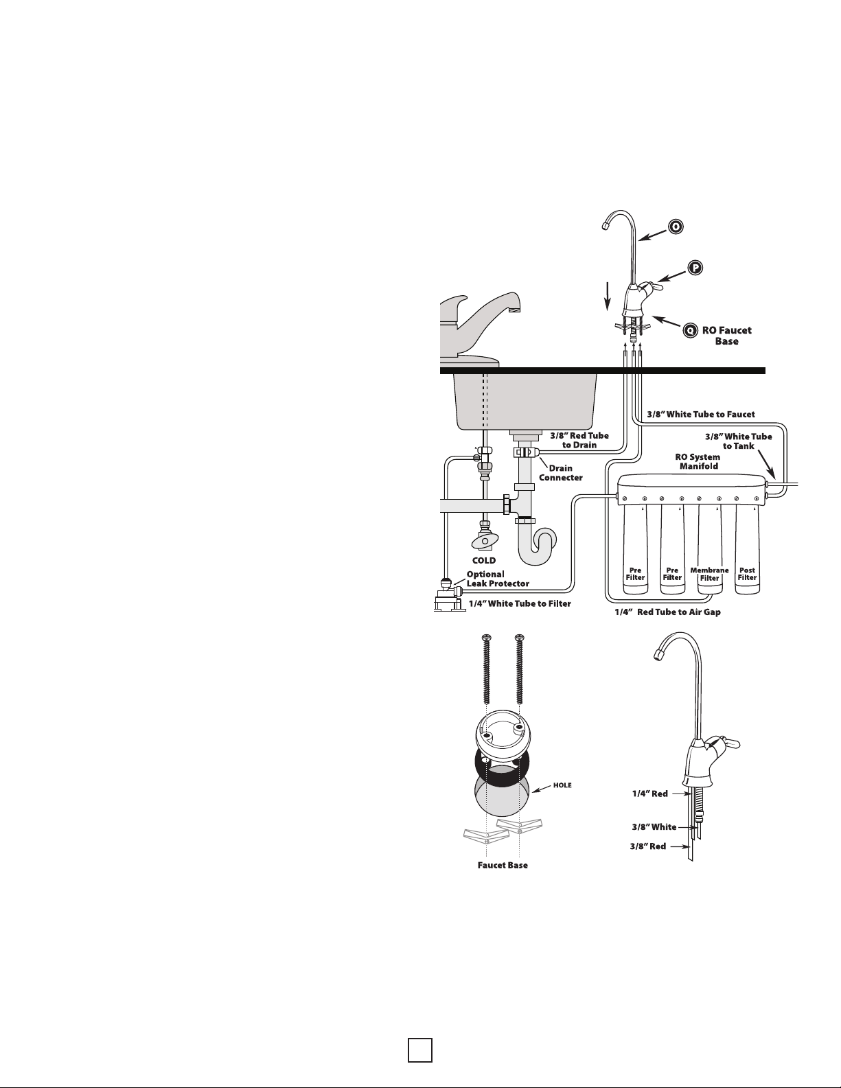
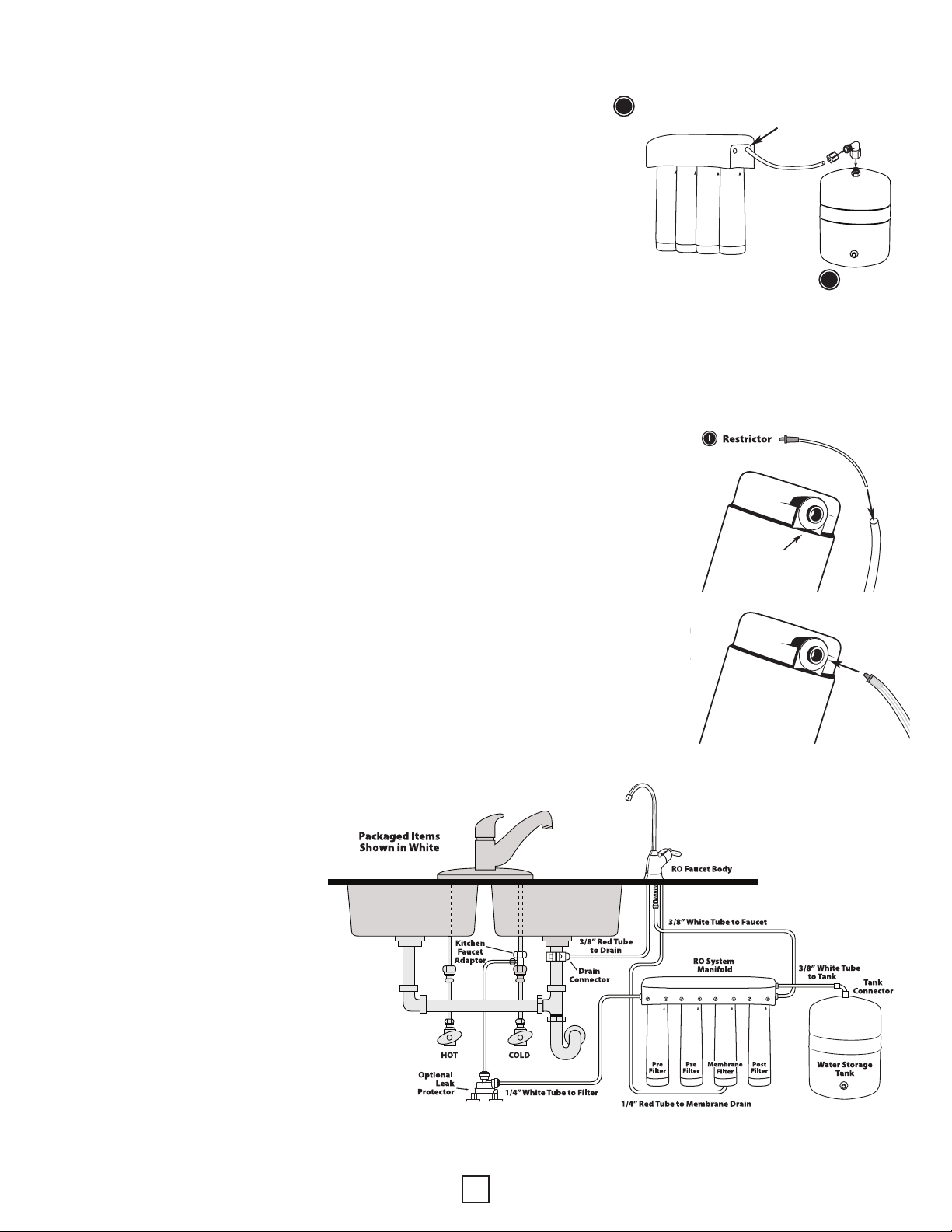
STEP SIX – CONNECT TUBING
Notice: For servicing, tubing lengths should allow
for removal of assembly from mount screws.
INSTALL TUBING FOR WATER SUPPLY LINE FROM
KITCHEN FAUCET ADAPTOR TO MANIFOLD INLET.
Notice: Do not bend or crimp tubing during this step.
1. Identify length of 1/4” white tubing necessary to
connect (A) manifold “INLET” to (F) kitchen faucet adaptor.
Allow sufcient tubing to prevent line kinking. Do not
discard remaining tubing.
2. With utility knife, cut the 1/4” white tubing
squarely to desired length.
3. With water, wet one end of tubing and push into the
kitchen faucet adaptor approximately 5/8” until it stops.
4. Wet other end of tubing and push into the manifold “INLET”
approximately 5/8” until it stops.
Notice: It is not necessary to remove tubing for routine maintenance and lter
exchanges, however, it may easily be disconnected if necessary. To disconnect,
turn off water supply to system and press in white collar around tting while
pulling tubing out with other hand.
INSTALL OPTIONAL LEAK PROTECTOR – PART NUMBER 49451
1. Turn off the water supply to the ltration system at the cold water source valve.
2. The leak protector should be mounted at in the lowest ground point
near the ltration system so in the event a leak occurs, the water will ow
in the direction of the valve.
3. Clean the designated installation area with rubbing alcohol.
4. Peel the red backing tape from the two mounting feet on the base of the
leak protector valve and press down rmly over the chosen install area.
You may also mount the valve using the screws included in the kit.
5. Cut the system’s water supply tube to plumb in the valve. Connect the
tube from the water source valve to the horizontal tting on the leak
protector valve labeled “in” by pushing the tubing in rmly until fully seated.
6. Connect the tube leading from the ltration system to the vertical tting on the
leak protector valve labeled “out” by pushing the tubing in rmly until fully seated.
7. Turn on the water supply to the ltration unit and check for leaks.
INSTALL TUBING FOR WATER SUPPLY LINE FROM MANIFOLD
OUTLET TO FAUCET.
1. Locate 3/8” white tubing already attached to faucet stem during Step 5 on page 6.
2. Identify length of tubing necessary to connect to manifold outlet labeled “FAUCET.”
3. Cut tubing squarely with utility knife. Do not discard remaining tubing.
4. With water, wet one end of tubing and push into manifold outlet labeled “FAUCET”
approximately 5/8” until it stops.
RO System
Manifold
Kitchen Faucet
Adapter
FInlet Water
Tube Connection
Manifold Outlet
for Faucet
A
from cold
water source
valve
from
Filtration
System
Optional Leak Protector