Cosel EAC Series User manual

EAC series
Small, common mode EMI/EMC Filters in 150kHz to 1MHz (1-Stage filter)
EAC -10 -472 -O
Ordering information
*
The dimensions change when the option is set.
Refer to External view.
1 2 3 4
Features of EAC series
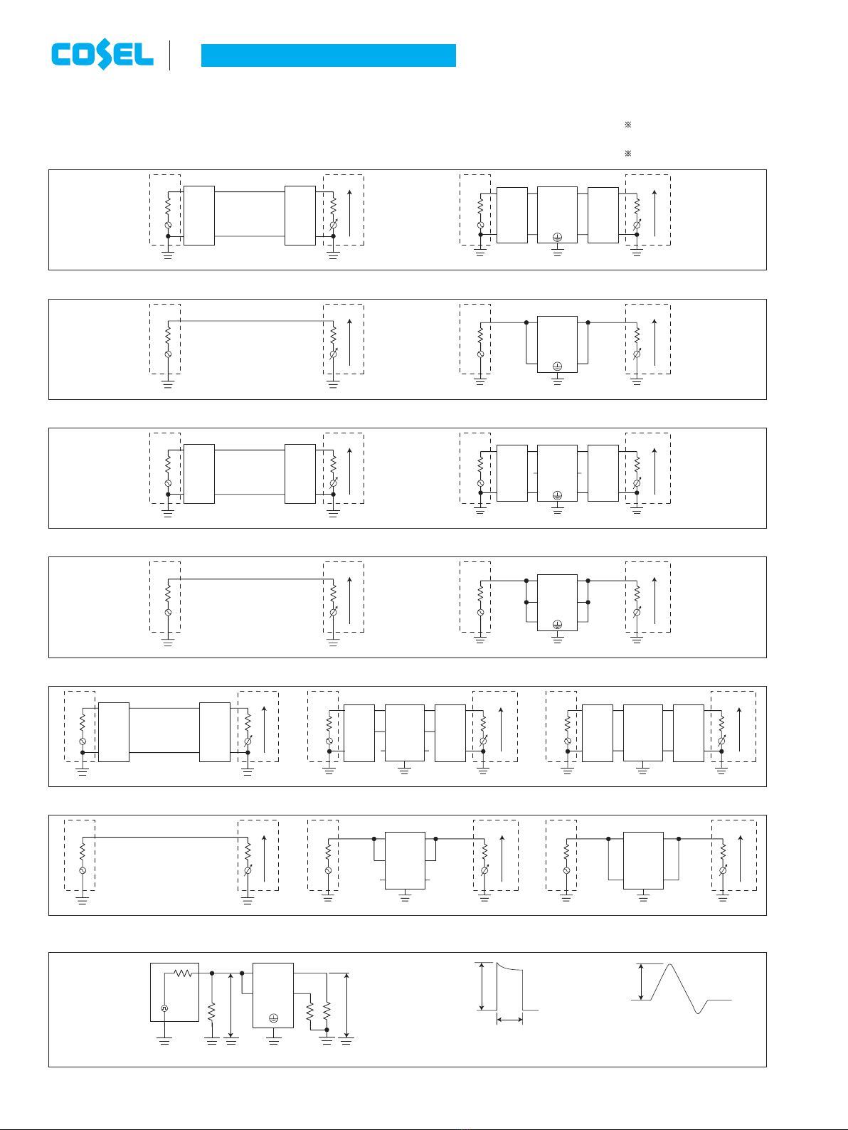
Circuit Diagram Derating Curve
LINE
Case
: Mounting Plate
1
24
3
CY
CY
CY : Line to ground capacitor
LOAD
Small, common mode EMI/EMC Filters in 150kHz to 1MHz(1-Stage filter)
-Single Phase 250 VAC -Small-size
-Quick and easy push-down terminal
Just connect the wires,push-down and tighten
the screws with a screwdriver
Ambient Temperature [C]
Load Factor [%]
9050 60 70 80
20
0
-4040-30-20
100
80
60
40
55
Specifications
No. Items EAC-03-472 EAC-06-472 EAC-10-472 EAC-16-472 EAC-20-472 EAC-30-472
1Rated Voltage[V] AC 1f250 / DC250
2 Rated Current[A] 3 6 10 16 20 30
3 Test Voltage (Terminal-Mounting Plate) 2,500 VAC (Cutoff Current = 20mA), 1minute at room temperature and humidity
4 Isolation Resistance (Terminal-Mounting Plate) 500 VDC 500MWmin at room temperature and humidity
5 Leakage current 125/250V 60Hz 0.5mA/1.0mA max
6 DC resistance 180mWmax 110mWmax 40mWmax 20mWmax 10mWmax 6mWmax
7 Safety agency approval temperatures -25 to +85C(Refer to Derating Curve)
8 Operating temperature -40 to +85C(Refer to Derating Curve)
9 Operating humidity 20 to 95%RH (Non condensing)
10 Storage temperature/humidity -40 to +85C/20 to 95%RH (Non condensing)
11 Vibration 10 to 55Hz, 19.6m/s2(2G), 3min. Period, 1hour each X, Y and Z axis
12 Impact 196.1m/s2(20G), 11ms Once each X, Y and Z axis
13 Safety agency approvals UL1283, CSA C22.2 No.8 (C-UL), DIN EN60939 VDE0565 Teil3-1, ENEC (At only AC input)
14 Case size (without projection) /Weight
39X30X85 mm [1.54X1.18X3.35 inches] (WXHXD) /170g max (Option : -D refer to external view)
DIN rail installation type is optionThe terminal cover is retracted inside the unit
1Model Name
2Rated Current
3Line to ground capacitor code:See table 1.1.
table1.1 Line to ground capacitor code
Code Leakage Current
(Input 125/250V 60Hz)
Line to ground
capacitor
(nominal value)
681 75.5 A/150 A max 680pF
102 0.13mA/0.25mA max 1000pF
222 0.25
mA/
0.5 mA max 2200pF
332 0.38mA/0.75mA max 3300pF
472 0.5 mA/
1.0 mA max 4700pF
*When the line to ground capacitor code is
different, the attenuation characteristic is
different.
4Options
D
:DIN rail installation type
EA/ES-1
R
July 08, 2020

EAC,EAM,EAP series
Mounting Plate
¶Closed the terminal cover
Terminal cover M4
M4
2-M4
2-M4
2-f4.8
Mounting Hole
Protection Earth
Name Plate
Terminal cover
Terminal cover
Protection Earth
85
[3.35]
[2.95]
[2.83]
[0.19]
75 ±0.5
72
39
31.5 ±0.5
12.7
[0.5]
[1.24]
[1.54]
11.5
21
2.5
[0.1][0.83]
[0.45]
9.7
[0.38]
30 2
[1.18] [0.08]
Terminal
Input
Terminal
Output
¶Tolerance : ±1 [±0.04]
¶Weight : 170g max
¶Mounting Plate : Iron (surface finishing:nickel plating)㹲=1.0 [0.04]
¶Case㸸PBT
¶Dimensions in mm, [ ]=inches
¶Terminal block screw tightening torque M4㸸1.6N࣭m(16.9kgf࣭cm)max
This product is shipped in the following condition,because it is equipped with push-down terminals.
1The terminal cover is retracted inside the unit.
2The screws for connecting the terminals are held in the up right position.
¡Note when installing the EMI/EMC
Filter on a DIN rail.
When the EMI/EMC Filter is grounded through
the DIN rail, the proper noise attenuation may not
be achieved.
Be sure to connect the protection earth (PE) of
the EMI/EMC Filter body to the earth.
It can connect the ground to either one only.
¶Closed the terminal cover
Mounting Plate
M4
M4
2-M4
2-M4
Protection Earth
Terminal cover
Terminal cover
Protection Earth
Terminal cover
DIN rail
Name Plate
8.5 +2
-1
85
[3.35] [0.33]
[0.1][0.83]
[0.45]
[2.83]
72
39
[1.54]
[0.5]
[1.18] [0.08]
[0.28]
[0.35] [0.38]
30 212.7
9.7
11.5
21
2.5
7
(9)
Terminal
Input
Terminal
Output
¶Tolerance : ±1 [±0.04]
¶Weight : 170g max
¶Mounting Plate : Iron (surface finishing:nickel plating)㹲=1.0 [0.04]
¶Case㸸PBT
¶Dimensions in mm, [ ]=inches
¶Terminal block screw tightening torque M4㸸1.6N࣭m(16.9kgf࣭cm)max
Standard Type
DIN rail installation Type
Name Plate
DIN rail
External view
EA/ES-4
July 08, 2020

Single Phase and Three Phase Input Type
Instruction Manual
(1) Single Phase
EMI/EMC
Filter Device
1
2
3
4
EMI/EMC
Filter Device
1
2
3
4
5
6
¶Three phase EMI/EMC filter is also available as a single phase
input type.
(2) Three phase (Delta-connection)
EMI/EMC
Filter Device
1
2
3
4
5
6
(3) Three phase (Star-connection)
Device
1
2
3
4
5
6
EMI/EMC
Filter
[Reference] Example of calculating input current calculation
Input voltage 400 [V]
Input capacity of the equipment 4000 [VA]
Input current = 4000 [VA]
400 [V]X3 = 5.8 [A]
1 Method of connecting
EMI/EMC Filter
2
Caution when connecting
EMI/EMC Filter
Please note the excessive temperature increase of EMI/EMC lter.
Please contact us if judgement is difcult.
(1) Input voltage and frequency
Please use within the rated voltage (or maximum voltage) of each
model.
Input frequency specification for AC input EMI/EMC filter is
considered as commercial frequency (50/60Hz).
It should not be used under the following conditions.
1) Distorted input voltage waveform.
(Triangle wave, square wave etc.)
2) High input frequency (ex: 400Hz)
(2) Input current
Please use within the rated current of each model.
EMI/EMC lters have short term peak current capability. Therefore,
it can ow ~40A or ten times of rated current, non-repeated, within a
few ms such as inrush current of power supply etc.
However, it should not be used under the following conditions.
1) Long duration peak current.
2)
Peak current or high-frequency current is continuously owing.
(3) Connection to a general-purpose inverter (servo driver)
Please connect EMI/EMC filter to input side of inverter driver
(servo driver).
It should not be used between the inverter (servo driver) and the
motor.
possibleimpossible
Inverter
or
servo driver Motor
possibleimpossible
Inverter
or
servo driver Motor
EMI/EMC
Filter
EMI/EMC
Filter
EMI/EMC
Filter
EMI/EMC
Filter
Three phase
input type
Single phase
input type
Manual-1 July 08, 2020

¡ To apply for safety standard approval using this EMI/EMC Filter,
the following conditions must be met.
¿ The unit must be used as a component of an end-use equipment.
¿Protection earth terminal (PE) must be connected to safety
ground of end-use equipment.
3
Safety Considerations
Single Phase and Three Phase Input Type
Instruction Manual
Manual-2
July 08, 2020

Method of measuring characteristic data
(1) Attenuation Characteristic(Static characteristic) Attenuation= 20log(U01/U02)[dB]
U01 : Voltage in state without filters
U02 : Voltage in state which added filters
N.A. : Network analyzer
¡Object product : Single phase input type (Differential mode)
5HIHUHQFH&RQQHFWLRQ
50
W
Balun
Balun
50
W
N.A.N.A.
U01
7HVW&RQQHFWLRQ
50
W
50
W
BalunBalun
EMI/EMC
Filter
N.A.N.A.
1
24
3
U02
■Object product : DC input type (Common mode)
+Vin
COM-in
-Vin
COM-out
+Vout
-Vout
+Vin
-Vin
+Vout
-Vout
Reference Connection
50
W
50
W
N.A.N.A.
U01
Test Connection(SNA)
50
W
50
W
N.A.N.A.
U02
Test Connection(SNR)
50
W
50
W
N.A.N.A.
U02
(SNA) (SNR)
EMI/EMC
Filter EMI/EMC
Filter
■Object product : Three phase input type (Common mode)
Reference Connection
50
W
50
W
N.A.N.A.
U01
Test Connection
50
W
50
W
N.A.N.A.
1
36
4
U02
25
EMI/EMC
Filter
¡Object product : Single phase input type (Common mode)
Reference Connection
50
W
50
W
N.A.N.A.
U01
Test Connection
50
W
50
W
N.A.N.A.
1
24
3
U02
EMI/EMC
Filter
Reference Connection
50
W
BalunBalun
50
W
N.A.N.A.
U01
Test Connection
50
W
50
W
BalunBalun
N.A.N.A.
1
36
4
25U02
EMI/EMC
Filter
■Object product : Three phase input type (Differential mode)
Test Connection(SNA)
50
W
BalunBalun
50
W
N.A.N.A.
U02
+Vin
COM-in
-Vin
COM-out
+Vout
-Vout
Test Connection(SNR)
50
W
BalunBalun
50
W
N.A.N.A.
U02
+Vin
-Vin
+Vout
-Vout
(SNA) (SNR)
Reference Connection
50
W
BalunBalun
50
W
N.A.N.A.
U01
EMI/EMC
Filter EMI/EMC
Filter
■Object product : DC input type (Differential mode)
(2) Pulse Attenuation Characteristic
50
W
50
W
50
W
50W
Noise
Simulator
Vi Vo
1
24
3
Input pulse waveform Output pulse waveform
Vi Vo
1msec
EMI/EMC
Filter
Single phase input type
Manual-3 July 08, 2020
This manual suits for next models
6
Table of contents
Other Cosel Water Filtration System manuals
Popular Water Filtration System manuals by other brands

Pelican
Pelican PCL3 owner's manual

HYDAC FILTER SYSTEMS
HYDAC FILTER SYSTEMS OLFP-6 /X-G/-T001 Installation and maintenance instructions

NKT Photonics
NKT Photonics SuperK SPLIT Product guide

Medivators
Medivators DSD-201 Instructions for Replacement and Disinfection

SpectraPure
SpectraPure MaxCap MC-RODI-180-MF Installation and operating manual

SteriPEN
SteriPEN Sidewinder user manual