Aesus Eco Shrink User manual


Eco Shrink Manual 2/45 Notice Regarding OSHA Regulations
NOTICE REGARDING OSHA REGULATIONS
Sellers shall not be responsible for any failure of compliance which results from the location, operation, use or maintenance
of the equipment or from alterations of the equipment by persons other than the seller, or from an option or accessory to
the equipment which was available to the buyer but omitted at the buyer’s direction. Sellers shall not be responsible for
design or instructions furnished by the buyer or his agents. Seller makes no warranties with respect to noise and will not be
responsible for any fines or penalties, or consequential damages.
Aesus Packaging Systems
Pointe-Claire (Montréal), Québec
Canada

Eco Shrink Manual 3/45 Table Of Contents
Table of Contents
NOTICE REGARDING OSHA REGULATIONS ...................................................................................................................2
Table of Contents..........................................................................................................................................................3
List of Tables .................................................................................................................................................................4
List of Figures................................................................................................................................................................4
1. Warranty & Terms and Conditions of Sale...........................................................................................................6
Disclaimer and Limitation of Liability ........................................................................................................................................ 7
2. General Description & Operations.......................................................................................................................8
3. Safety Features...................................................................................................................................................11
3.1 Emergency Stop Push Button ..................................................................................................................................... 11
3.2 Safety Door Guarding ................................................................................................................................................. 11
3.2.1 Knife/Blade Safety Protection Guard .................................................................................................................. 11
3.3 Main Power Disconnect Switch .................................................................................................................................. 11
4. Sleeve Roll Threading Path.................................................................................................................................12
5. Setup ..................................................................................................................................................................16
5.1 Safety Warning ........................................................................................................................................................... 16
6. Setup ..................................................................................................................................................................18
6.1 Sleeve Roll Threading.................................................................................................................................................. 18
6.1.1 Mandrel Installation............................................................................................................................................ 21
6.1.2 Photo Registration Sensor Setup (Optional) ....................................................................................................... 22
6.1.3 Guide Rail Setup (Optional)................................................................................................................................. 22
6.1.4 Indexing Gate Setup ............................................................................................................................................ 22
6.1.5 Star Wheel Setup (Optional) ............................................................................................................................... 23
6.1.5.1 Servo Driven Starwheel Adjustment (Optional).......................................................................................... 24
6.1.6 Feedscrew Indexing Setup (Optional) ................................................................................................................. 25
6.1.7 Start and Backup Sensor Setup (Optional).......................................................................................................... 26
6.1.8 Product at Mandrel Sensor Setup (Optional)...................................................................................................... 26
6.1.9 Band Tacker Adjustment (Optional).................................................................................................................... 27
6.1.10 Knife Airflow Adjustment (Optional)................................................................................................................... 27
6.1.11 Knife Servo Motor Adjustment (Optional) .......................................................................................................... 27
6.1.11.1 Knife Adjustment ........................................................................................................................................ 27
6.1.12 Sleeve Assembly Height Adjustment................................................................................................................... 28
6.1.13 Perforator Adjustment (Optional)....................................................................................................................... 29
6.1.14 Band Tapper Adjustment (Optional) ................................................................................................................... 29
6.1.15 Whiskers Adjustment (Optional)......................................................................................................................... 30
6.1.16 Coder Adjustment (Optional).............................................................................................................................. 30
6.2 Air Pressure Adjustment............................................................................................................................................. 30
7. Machine Controls...............................................................................................................................................32
7.1 Control Panel Buttons................................................................................................................................................. 32
7.2 Shrink Human-Machine Interface Control.................................................................................................................. 33
7.2.1 HMI Main Screen................................................................................................................................................. 33
7.2.1.1 Info Button.................................................................................................................................................. 33
7.2.1.2 Stats Button ................................................................................................................................................ 34
7.2.1.3 Login Menu ................................................................................................................................................. 34
7.2.2 Menu Button / Main Menu................................................................................................................................. 35
7.2.3 Film Setup Page 1................................................................................................................................................ 35
7.2.3.1 Film Setup Page 2........................................................................................................................................ 36
7.2.3.2 Film Setup Page 3........................................................................................................................................ 36
7.2.3.3 Film Setup Page 4........................................................................................................................................ 36
7.2.3.4 Band Setup Page 5 ...................................................................................................................................... 37

Eco Shrink Manual 4/45 Table Of Contents
7.2.4 Infeed/Outfeed Setup Screen Page 1................................................................................................................. 37
7.2.4.1 Infeed/Outfeed Setup Screen page 2 ......................................................................................................... 37
7.2.4.2 Infeed/Outfeed Setup Screen page 3 ......................................................................................................... 38
7.2.5 Housing Lift Setup ............................................................................................................................................... 38
7.2.6 Machine Test Menu ............................................................................................................................................ 38
7.2.7 Recipe Management Menu................................................................................................................................. 38
7.2.7.1 Navigation controls:.................................................................................................................................... 39
7.2.7.2 Recipe controls: .......................................................................................................................................... 39
7.2.7.3 Save As Function......................................................................................................................................... 39
7.2.7.4 Rename Function........................................................................................................................................ 39
7.2.7.5 Recipe Help ................................................................................................................................................. 39
7.3 Step to transfer program to USB Memory Stick from HMI......................................................................................... 39
7.4 Step to transfer program to HMI from USB Memory Stick......................................................................................... 40
8. Starting the Machine..........................................................................................................................................41
9. Troubleshooting.................................................................................................................................................42
10. Contact Information...........................................................................................................................................44
11. Some of the other Machinery Manufactured by Aesus Packaging Systems .....................................................45
List of Tables
Table 1: Start & Backup Sensors Adjustments ............................................................................................................................. 26
Table 2: List of Machine’s Current State ...................................................................................................................................... 33
Table 3: Summary of HMI permissions ........................................................................................................................................ 34
Table 4: Quick Troubleshooting & Solution ................................................................................................................................. 42
List of Figures
Figure 2-1: Eco Shrink Labeller Typical Machine Overview............................................................................................................ 9
Figure 2-2: Eco Shrink Sleeving Machine 3D Schematic............................................................................................................... 10
Figure 3-1: Main Cabinet Guarding .............................................................................................................................................. 11
Figure 3-2: Knife/Blade Safety Protection.................................................................................................................................... 11
Figure 3-3: Main Power Disconnect Switch.................................................................................................................................. 11
Figure 4-1: Sleeve Roll threading path ......................................................................................................................................... 12
Figure 4-2: Sleeve Roll threading path—Eco Shrink with Motorized Unwinder .......................................................................... 13
Figure 4-3: Sleeve Roll threading path—Eco Shrink with Motorized Unwinder and angle corrector.......................................... 14
Figure 4-4: Sleeve Roll threading path—Eco Shrink with Motorized Unwinder and T-perf......................................................... 15
Figure 5-1: Safety Warning........................................................................................................................................................... 17
Figure 6-1: Film Roll Feed Direction ............................................................................................................................................. 18
Figure 6-2: Film Cover .................................................................................................................................................................. 18
Figure 6-3: Film Alignment ........................................................................................................................................................... 18
Figure 6-4: Slip Clutch................................................................................................................................................................... 18
Figure 6-5: Film Resistance........................................................................................................................................................... 19
Figure 6-6: Film Feeder ................................................................................................................................................................ 19
Figure 6-7: Drive Roller & Vertical Perf ........................................................................................................................................ 19
Figure 6-8: Knurled Pressure Roller.............................................................................................................................................. 19
Figure 6-9: Dancer Rollers Bottom View ...................................................................................................................................... 20
Figure 6-10: Dancer Rollers Top View .......................................................................................................................................... 20
Figure 6-11: Dancer Rollers Path Left-hand side Unwinder ......................................................................................................... 20
Figure 6-12: Dancer Rollers Path Right-hand side Unwinder....................................................................................................... 21

Eco Shrink Manual 5/45 Table Of Contents
Figure 6-13: Mandrel and Mandrel Donut ................................................................................................................................... 21
Figure 6-14: Sleeve placed over Mandrel..................................................................................................................................... 21
Figure 6-15: Mandrel in Position.................................................................................................................................................. 22
Figure 6-16: Photo Registration Sensor........................................................................................................................................ 22
Figure 6-17: Guide Rails ............................................................................................................................................................... 22
Figure 6-18: Indexing Gates ......................................................................................................................................................... 23
Figure 6-19: Indexing Gates Adjustment...................................................................................................................................... 23
Figure 6-20: StarWheel and Pneumatic Cylinders........................................................................................................................ 23
Figure 6-21: Starwheel Position Adjustments.............................................................................................................................. 24
Figure 6-22: Rear Support Rail ..................................................................................................................................................... 24
Figure 6-23: Starwheel Adjustments............................................................................................................................................ 24
Figure 6-24: Starwheel Adjustments 2......................................................................................................................................... 25
Figure 6-25: Starwheel pocket Qty parameter............................................................................................................................. 25
Figure 6-26: Feedscrew Installation ............................................................................................................................................. 25
Figure 6-27: Feedscrew Assembly Position Adjustments............................................................................................................. 26
Figure 6-28: Start/Backup Sensor................................................................................................................................................. 26
Figure 6-29: Product at Mandrel Sensor ...................................................................................................................................... 27
Figure 6-30: Band Tackers Adjustments....................................................................................................................................... 27
Figure 6-31: Knife Airflow Adjustment Knobs .............................................................................................................................. 27
Figure 6-32: Knife in Home Position............................................................................................................................................. 27
Figure 6-33: Knife/Blade Servo Motor (Optional) ........................................................................................................................ 28
Figure 6-34: Knife in Middle Position ........................................................................................................................................... 28
Figure 6-35: Sleever Height Adjustment Ruler (through HMI) (Optional).................................................................................... 28
Figure 6-36: Sleever Height Adjustment (with Crank).................................................................................................................. 29
Figure 6-37: Perforator................................................................................................................................................................. 29
Figure 6-38: Band Tapper............................................................................................................................................................. 29
Figure 6-39: Band Tapper Trigger Sensor..................................................................................................................................... 30
Figure 6-40: Whiskers................................................................................................................................................................... 30
Figure 6-41: Coder (Optional) ...................................................................................................................................................... 30
Figure 6-42: Main Air Pressure Regulator .................................................................................................................................... 31
Figure 7-1: Eco Shrink Control Panel............................................................................................................................................ 32
Figure 7-2: HMI Main Screen—No Alarms Screen ....................................................................................................................... 33
Figure 7-3: HMI Main Screen—Active Alarms Screen.................................................................................................................. 33
Figure 7-4: Info Screen ................................................................................................................................................................. 34
Figure 7-5: Statistics Screen ......................................................................................................................................................... 34
Figure 7-6: Login Menu ................................................................................................................................................................ 34
Figure 7-7: Main Menu................................................................................................................................................................. 35
Figure 7-8: film Setup Screen (pg.1)............................................................................................................................................. 35
Figure 7-9: Film Setup Screen (pg.2) ............................................................................................................................................ 36
Figure 7-10: Film Setup Screen (pg.3) .......................................................................................................................................... 36
Figure 7-11: Film Setup Screen (pg.4) .......................................................................................................................................... 36
Figure 7-12: Band Setup Screen (pg.5)......................................................................................................................................... 37
Figure 7-13: Infeed/Outfeed Setup Screen page 1....................................................................................................................... 37
Figure 7-14: Infeed/Outfeed Setup Screen page 2....................................................................................................................... 37
Figure 7-15: Infeed/Outfeed Setup Screen page 3....................................................................................................................... 38
Figure 7-16: Housing lift Setup Screen ......................................................................................................................................... 38
Figure 7-17: Machine Test Screen................................................................................................................................................ 38
Figure 7-18: Recipe Management Menu...................................................................................................................................... 39
Figure 7-19: Recipe Help screen................................................................................................................................................... 39

Eco Shrink Manual 6/45 Warranty & Terms and Conditions of Sale
1. Warranty & Terms and Conditions of Sale
AESUS refers to Aesus Labelling Systems, Aesus Packaging Systems Inc, and DL Tech Inc.
GUARDING: Guarding provided may not suit your local requirements. Additional guarding is available at extra cost and can be provided to meet your
requirements. Please examine the guarding included and advise us immediately should you require any changes.
PERFORMANCE GUARANTEES: The performance of Aesus machinery to do a particular task, at a particular speed, with a customer’s products (caps,
containers, labels, shrink sleeves, etc.) depends on many variables. These variables may also include the ambient temperatures, the environment, the quality
of the components, the quality of the film or the labels, the backing paper, the design of the container, and possibly many other considerations. Aesus in the
light of their experience attempt to provide what Aesus deems is an acceptable and/or affordable solution. Therefore, due to so many possible variables,
Aesus cannot positively guarantee all aspects of performance. Customers are expected to perform a final acceptance test at Aesus’s facility with as many of
their components as possible, and Aesus will do their absolute best to help the customer find a solution to any challenging issues, only charging the customer
at Aesus’s cost for the work done in the attempt to find an acceptable solution.
TESTING: Quotations are always subject to final testing of bulk samples. Changes and additional costs incurred in order to achieve proper operation, or to
reach estimated speeds of the machinery, after testing of bulk samples, will be charged at cost, when not otherwise agreed to in advance. In those cases
where bulk samples are not supplied, equipment will be tested for normal functioning only. Performance on products not submitted whether expressed or
implied cannot be guaranteed.
OTHER MANUFACTURERS: It should be understood that although Aesus will do their best to ensure that coders, vision systems, barcode readers, UV
detection systems, etc., that are manufactured by others but integrated by Aesus, perform appropriately at installations and during FATs (should the
customer have purchased FAT tests at Aesus, or with Aesus in attendance at the customer’s facility), Aesus does not guarantee these items, nor will Aesus be
held responsible to delivery delays caused by deficiencies of such systems. The customer should do their due diligence in the choice of coding and checking
systems that are appropriate. Aesus may facilitate the process by purchasing these items on behalf of the customer, but it is understood that Aesus passes
the warranty (ies) of these items to the customer upon delivery of the machine. If any of these systems fail to perform, the customer should deal directly
with the supplier in question, although Aesus will do their best to help facilitate this process.
An ”Aesus in attendance” run is a test of a duration that is acceptable to both Aesus and the customer (at suitable charges) at an Aesus facility or at the
customer’s facility, with qualified Aesus engineer(s) in attendance for the purpose of qualifying and accepting the machine (FAT).
SAMPLES AND TEST MATERIAL: In order to confirm the order and the estimated time for machine manufactures, representative samples of all materials and
containers to be used on the machine must be available at the factory. Samples, as requested, are to be forwarded free of charge, freight prepaid to the
factory by the customer, indicating minimum values for customs purposes where applicable. All samples will be returned with all the tested machinery. In
the case where returning product will significantly increase the freight costs, the buyer will have the option of paying for proper disposal of their samples.
Normally a 15 minute “production run” of samples of each size bottle (or more), and adequate samples of products, band, or other consumables are
required in order to ensure the proper operation of the machine. Samples must be sent free of charge, freight and duties prepaid to arrive within 30 days of
order date. Late delivery of the samples will result in late delivery of the machine.
MATERIALS AND CONSUMABLES: Aesus assumes no responsibility for materials and consumables purchased by the buyer regardless of testing performed
and recommendations made. Aesus recommends that the customer does not buy considerable quantities of consumables such as film, band, sleeving, caps,
labels, etc. until final satisfactory tests have been conducted to prove suitability of such.
MACHINE ACCEPTANCE: When machinery is complete, the customer will be requested to visit the Factory for machine Acceptance Testing (FAT). All features
will be demonstrated, as well as a five-minute continuous production run on all sizes of samples supplied. Additional charges apply for longer acceptance
tests or when more than 3 product sizes are to be tested. The machine will be deemed to be complete and accepted by the customer when the
manufacturer has demonstrated the machinery operating at the required speeds and quality specified.
ON-SITE ACCEPTANCE TESTING: Customers have the option of having the acceptance tests repeated at their facilities, by contracting for a representative of
the original equipment manufacturer or Aesus to carry out the test on-site, at prevailing rates.
INSTALLATION LABOUR AND TRAINING: Installation of and training on equipment and accessories is not included and can be done by Aesus or by those of
Aesus’s agents and representatives on request at prevailing rates. Note that some equipment such as coders, vision systems, barcode readers, UV detection
systems, etc., that are manufactured by others (OEMs) but integrated by Aesus, can be complicated and Aesus technicians may not be familiar with many
aspects of these items. Customers should also consider engaging OEM trained technicians for these complicated systems. When equipment is not installed
by us, Warranties shall be limited to replacement of defective parts, FOB supplier factories, supplied prepaid and credited on return of defective parts.
DAMAGE CLAIMS: Great care is taken in packing all machines, parts and accessories. All claims for breakage or damage whether concealed or obvious must
be made to the carrier as soon as possible after receipt of the shipment.
WARRANTEE: Equipment and Component warranties are in accordance with those of the original equipment supplier, but for Aesus manufactured
components shall be 12 months, based on single shift usage. Wear parts, and those parts found not to be installed according to the equipment
manufacturers or Aesus instructions, abused, not used in accordance with the application originally intended, or modified without prior approval of the
original equipment manufacturer or Aesus are excluded. Labour or travel to replace defective parts is not included.

Eco Shrink Manual 7/45 Warranty & Terms and Conditions of Sale
The foregoing is the only warrantee made by the seller, and the seller specifically disclaim all other warranties, express or implied, including but not limited
to, the implied warranties of marketability and fitness for a particular purpose.
LIMITS OF LIABILITY: Liability of the original Equipment supplier, Aesus’s, its agents, distributors, and representatives, for any damages suffered by the buyer
or its customers, whether in contract or otherwise, shall be limited to the amount paid to the seller by the buyer in reference to the equipment supplied, and
in no case shall a seller be liable for any special, indirect, or consequential damages (including loss of goods, loss of profits, loss of opportunity, replacement
costs or other) of buyers, any customer, or of any third party, even if sellers have been previously advised of the possibility of such damages.
RETURN OF GOODS: In no case can any material or equipment be returned to us without our prior written acceptance.
FORCE MAJEURE : Under no circumstances can Aesus or their representatives be responsible for delays caused by Force Majeure. Force Majeure includes
strikes, wars, riots, floods, fires, earthquakes, and other such eventualities out of the control of Aesus or their representatives.
WAIVER: Our failure to insist upon any of these terms and conditions shall not be deemed a waiver of any rights that Aesus may have, and shall not be
deemed a waiver of any subsequent breach or default in these terms and conditions.
PERMITS: Permits and inspections, when not specified, required for the installation and/or use of the equipment furnished, must be applied for by the buyer
at their own expense.
TAXES, excises, or other charges imposed by any local, state, or federal authority, which have to do with or affect the goods herein ordered, shall be assumed
and paid by the buyer. Bank charges and fees for legalization or certification of documents are not included.
SPECIFICATIONS: Specifications, machine designs, and features are subject to change without notice unless specifically agreed to in advance.
COPYRIGHT: This proposal, specifications, literature material, and all technical details are the property of Aesus and are supplied for the sole purpose of
evaluating equipment to be supplied by Aesus. Any reproduction or redistribution without our prior written consent is strictly prohibited.
CLAIMS: Any claim for consequential or incidental damages and any claims, right of action and demands, regardless of how they are described, whether in
law or equity, shall be interpreted according to the laws of the Province of Quebec, Canada and they shall be pursued solely in the Province of Quebec,
Canada.
ACCEPTANCE AND USE OF MACHINERY:
Acceptance and/or use of this packaging machine include acceptance of all terms and conditions included herein.
Disclaimer and Limitation of Liability
IT IS UNDERSTOOD AND AGREED THAT SELLER’S LIABILITY FOR ANY DAMAGES SUFFERED BY BUYERS OR ITS CUSTOMERS,
WHETHER IN CONTRACT, IN TORT, UNDER ANY WARRANTY THEORY, IN NEGLIGENCE OR OTHERWISE, SHALL BE LIMITED TO
THE AMOUNT PAID TO SELLERS BY BUYER PURSUANT TO THE CONTRACT. UNDER NO CIRCUMSTANCES SHALL A SELLER BE
LIABLE FOR ANY SPECIAL, INDIRECT OR CONSEQUENTIAL DAMAGES (INCLUDING LOST PROFITS) OF BUYERS, ANY CUSTOMER,
OR ANY OTHER THIRD PARTY, EVEN IF SELLERS HAS BEEN PREVIOUSLY ADVISED OF THE POSSIBILITY OF SUCH DAMAGES.

Eco Shrink Manual 8/45 General Description & Operation
2. General Description & Operations
The Aesus Eco Shrink machine is a Banding Labeller controlled by a Human-Machine interface (HMI). The machinery is well
designed and can include oversized supports, stainless steel panels, optional safety guarding, compact footprint and other
excellent features too numerous to list.
The Aesus Shrink Labellers have certainly very exclusive advantages which include a servo motorized precision blade knife
operating as a guillotine type and equipped with dancing film tension rollers.
The Bands or Sleeves are applied to the container, directly from the mandrel. This means there is no secondary side transfer
or vacuum cups or other movements. Sleeves go right on the container. As Aesus Shrink machines apply directly from the
mandrel this results in having a band that more closely fits the container, thereby saving band material costs, and giving
better final shrink characteristics. The closer the band fits the container the smaller percentage of shrink needed.
As the bands are not released until they are on the container static electricity has virtually no effect. If you have very short
bands and lots of static then Aesus optional proprietary band tacker can be enabled right at the application station to ensure
the band stays put. This is activated directly from the control panel, and saved away as a recipe to be recalled for subsequent
use once setup correctly.
The larger the container diameter the better our machines stand up against the competition because we control the band
right onto the neck, and then if needed tacked. Very short bands (3 mm or so) can also be applied by our Shrink Labellers,
where other machines lose total control. The Eco Shrink Labeller has a large spectrum of film length. Dial in any length at the
control panel using our unique is servo band feed mechanism.
Both clear and printed band material can be run on the same machine with the optional photo registration device.
The new T-PERF option for sleeving enables a horizontal neck tear off plus a short vertical tear strip. Therefore there is a PERF
that goes around the neck as well as a tear strip for the neck.
The Aesus Eco Shrink machines are rugged and reliable in operation. They require only a minimum of maintenance and use
the most current methods of mechanical and electronic technology. All processes comply with current Good Manufacturing
Practices.
For ease of visualization, the principal components of the Eco Shrink Banding machine are presented using different colours:
Bands or Sleeves feeder , HMI , Shrink Labeller and the
product Conveyor .
Refer to Figure 2-1 to Figure 2-2 following.

Eco Shrink Manual 9/45 General Description & Operation
Figure 2-1: Eco Shrink Labeller Typical Machine Overview
Sleeve Roll Feeder
Knife!!
Shrink/Banding/Sleeving
Labeller Housing
(Indexing Gates)
Conveyor (optional)
Human-Machine
Interface (HMI)
Control Panel
Dancing Film
Tension Rollers

Eco Shrink Manual 10/45 General Description & Operation
Figure 2-2: Eco Shrink Sleeving Machine 3D Schematic
**NOTE: The pictures included in this document may not be exactly the same as your machine depending on your configuration/options.
Shrink/Banding/Sleeving
Labeller Housing
(Indexing Gates)
Human-Machine
Interface (HMI)
Control Panel
Sleeve Roll Feeder
Dancing Film
Tension Rollers
Conveyor (optional)
Feedscrew

Eco Shrink Manual 11/45 Safety Features
3. Safety Features
As is the case with all automated equipment, machinery can present safety hazards if safety guidelines are not followed. The
guidelines which follow are for operator and maintenance personnel safety. Before proceeding with this manual make sure to
read and understand the safety features outlined in this section.
3.1 Emergency Stop Push Button
The Emergency Stop (E-Stop) Push button cuts the control
power supplied and stops the machine operation instantly
once pressed no matter where the current cycle is (hard
stop). It should only be pressed in case of an emergency
where the machine operation must be stopped
immediately. It should not be used as a normal cycle stop
function. In order to restart the system, the cause of the
emergency stop must be identified and rectified, the E-
Stop button on the control panel enabled, and the alarm
acknowledged on the Alarm screen before restarting
production.
3.2 Safety Door Guarding
The moving components of the Eco Shrink machine are
guarded by interlocked guard doors (Figure 3-1). The
system cannot operate with the doors open and must be
closed, alarm acknowledged, and systems reset in order
to resume operations.
Figure 3-1: Main Cabinet Guarding
3.2.1 Knife/Blade Safety Protection Guard
A safety protection is added to prevent from inadvertent
access to the sharp knife/blade.
Figure 3-2: Knife/Blade Safety Protection
3.3 Main Power Disconnect Switch
The Aesus Shrink machine is equipped with a MAIN
POWER disconnect switch which is used to power up the
system when the switch is turned to its ON position
(Figure 3-3). The switch is located on the main cabinet
located in front of the system. When the switch is turned
to its OFF position, all power to the system is removed.
Unless stated otherwise in this manual, the MAIN POWER
disconnect switch should always be in the OFF position
when servicing or executing preventive maintenance
procedures on the system.
Figure 3-3: Main Power Disconnect Switch
Knife/Blade
without
Safety Guard
Knife/Blade
Safety Guard
Eco Shrink Manual 12/45 Film Path
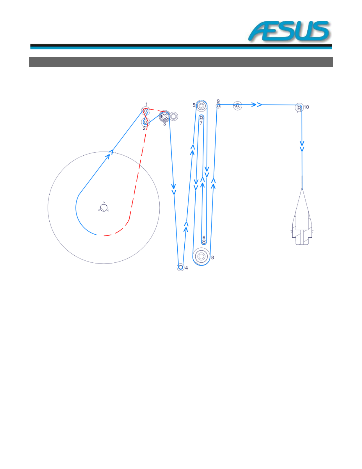
4. Sleeve Roll Threading Path
Figure 4-1: Sleeve Roll threading path
**NOTE: The pictures included in this document may not be exactly the same as your machine depending on your configuration/options.

Eco Shrink Manual 13/45 Film Path
Figure 4-2: Sleeve Roll threading path—Eco Shrink with Motorized Unwinder
**NOTE: The pictures included in this document may not be exactly the same as your machine depending on your configuration/options.
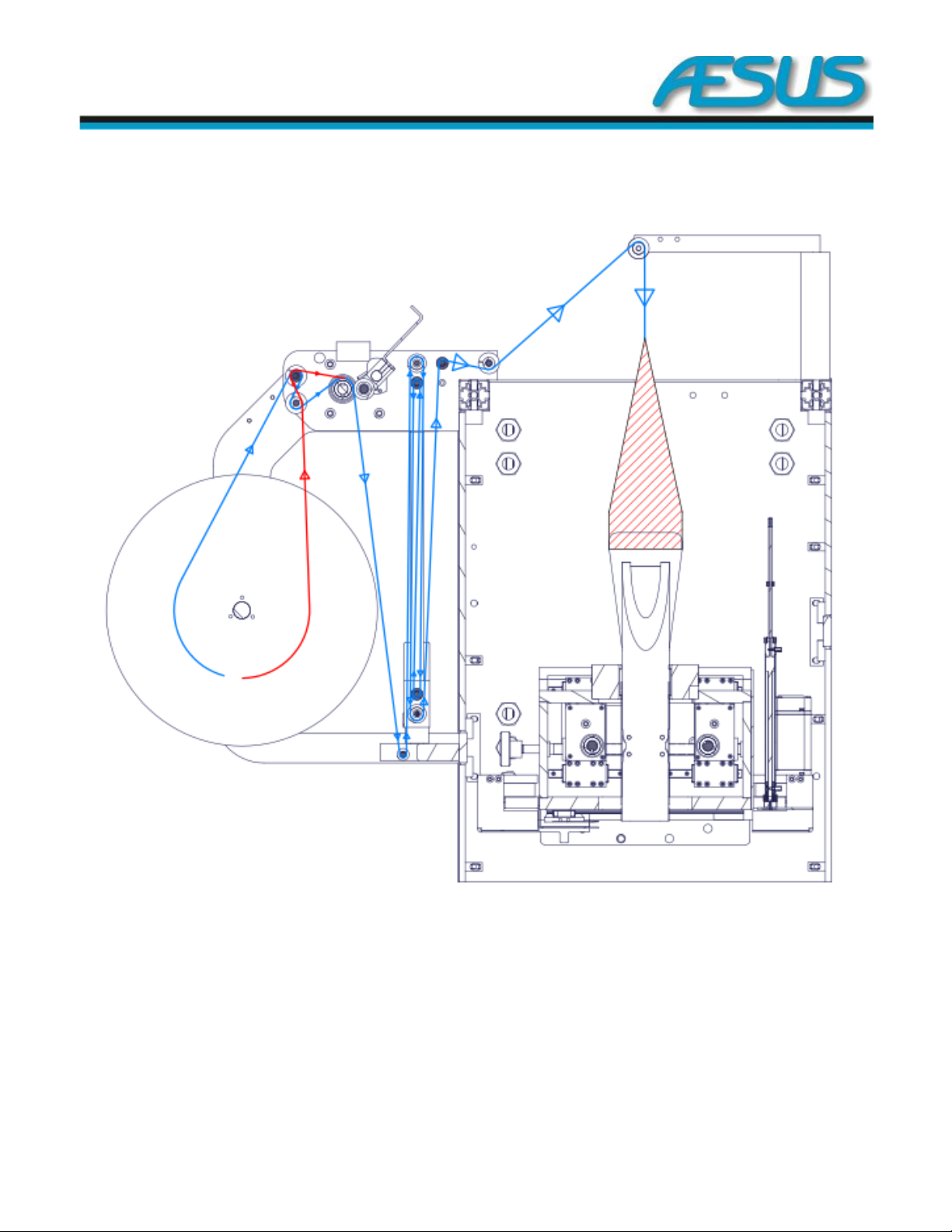
Eco Shrink Manual 14/45 Film Path
Figure 4-3: Sleeve Roll threading path—Eco Shrink with Motorized Unwinder and angle corrector
**NOTE: The pictures included in this document may not be exactly the same as your machine depending on your configuration/options.

Eco Shrink Manual 15/45 Setup
Figure 4-4: Sleeve Roll threading path—Eco Shrink with Motorized Unwinder and T-perf
**NOTE: The pictures included in this document may not be exactly the same as your machine depending on your configuration/options.

Eco Shrink Manual 16/45 Setup
5. Setup
5.1 Safety Warning
IMPORTANT:
The next page is a safety warning for working on
the machine. It is strongly recommended that you
print at least one copy of the warning page and
place it on or near the machine.

Eco Shrink Manual 17/45 Setup
**Always engage the Emergency Stop or turn off Main Power when working on the Machine.**
NOTE: The pictures included in this section may not be exactly the same as your machine depending on your configuration.
OPEN THE DOOR BEFORE ACCESSING OR E-
STOP!!
Figure 5-1: Safety Warning
Eco Shrink Manual 18/45 Setup
6. Setup
6.1 Sleeve Roll Threading
Use the diagram shown below and supplied on the
equipment as a guide to thread the film through the
machine.
**Please note all descriptions are for a Left to Right machine, please do
the mirror for a Right to Left machine.**
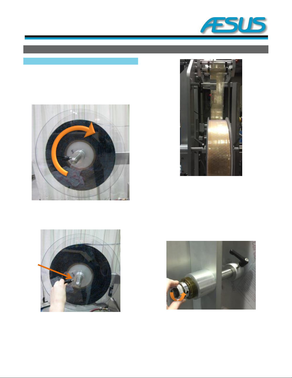
Figure 6-1: Film Roll Feed Direction
a. Place the roll of film on the machine oriented to
unroll from the top.
Figure 6-2: Film Cover
Film Cover—Place the outer film cover firmly against the
roll and tighten ratchet handle. Make sure that both film
covers are aligned (Film must be snug between the two
plastic film covers).
Figure 6-3: Film Alignment
b. Film Alignment—Align Film with middle of the
machine making sure it is properly aligned with
the mandrel once it is threaded. You may need to
adjust it.
**Note: If the film is not aligned properly it may cause unneeded
pulling on the film. This can cause the film to tear or fold. If you have a
vertical perf system on the machine, misalignment can cause the perf
to move along the film from it pulling.
Figure 6-4: Slip Clutch
c. Film Feeder Slip Clutch—Tighten the Slip clutch
so that if you give the Film a tug the roll will
rotate a quarter to half a turn.
Eco Shrink Manual 19/45 Setup
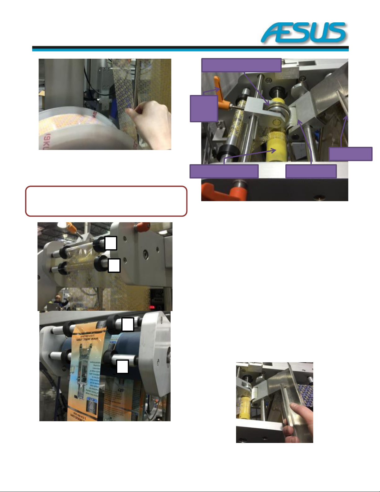
Figure 6-5: Film Resistance
d. Test Slip Clutch—A quick tug checks that the slip
clutch is correctly set.
NOTE: If your machine does not have a
Motorized Unwinder, directly jump to the
Section 6.1.1.
Figure 6-6: Film Feeder
e. The film now needs to come from the film roll up
over roll 1 shown above, then under roll 2 shown
above.
Figure 6-7: Drive Roller & Vertical Perf
f. Pass the film up over the yellow or blue drive
roller. In order to do this you will have to loosen
the vertical perf wheel (optional) by loosening
the orange ratchet handle and then rotating it up
out of the way.
g. Using the stainless lever on the knurled roller,
move it out of the way in order to pass the film
down between it and the yellow drive roller.
h. Adjust the vertical perf’s pressure against the
sleeve and the yellow drive roller to achieve the
desired amount of perforation. This vertical
perforation can be adjusted left to right. You can
also do this once the film has been completely
threaded.
i. Ensure the sleeve is centred on the Drive Roller.
Rotate the Knurled pressure roller so it applies
light pressure on the sleeve and tighten the
handles to hold it in position.
Figure 6-8: Knurled Pressure Roller
1
2
1
2
Vertical Perf (optional)
Orange
Ratchet
Handle
Yellow (Blue) Drive Roller
Knurled Roller
Stainless Lever
Eco Shrink Manual 20/45 Setup
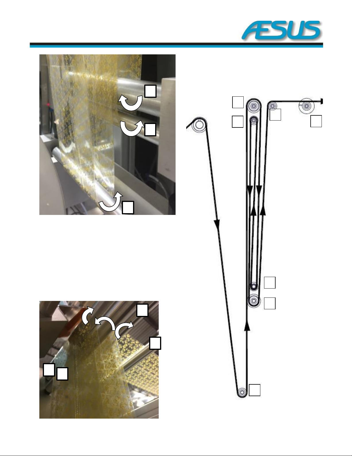
Figure 6-9: Dancer Rollers Bottom View
j. Pass down the bottom roller #1 rotating around
the roller counterclockwise.
k. Pass up over the top roller #2 clockwise.
l. Pass down clockwise around the bottom roller #
3.
m. Pass up counterclockwise around the top roller
#4.
n. Pass down counterclockwise around the bottom
roller #5.
o. Pass up over roller #6 clockwise, and then over
the roller #7.
p. Now pass the film to the middle front of the
machine.
Figure 6-11: Dancer Rollers Path
Left-hand side Unwinder
1
2
3
4
5
6
7
1
5
3
2
4
6
7
Figure 6-10: Dancer Rollers Top View
Table of contents


