AET AET111 User manual

0552
15.04.05
AET
MULTIFUNCTION MEASURING TRANSDUCER
Operation manual
47113964.2.023РЭ

47113964.2.023РЭ
2
Contents
1 Description and operation .................................................................... 3
1.1 General specification ............................................................. 3
1.2 Technical characteristics ....................................................... 5
1.3 Construction .......................................................................... 11
1.4 Functional description ........................................................... 11
1.5 Marking and sealing .............................................................. 14
1.6 Packing .................................................................................. 14
2 Intended use ........................................................................................ 16
2.1 Operational constraints .......................................................... 16
2.2 Preparation for use ................................................................. 16
2.3 Use ......................................................................................... 15
2.4 Operation in extreme conditions ........................................... 17
3 Verification procedure ......................................................................... 18
3.1 Verification Operations and Test Equipment ........................ 18
3.2 Safety requirements ............................................................... 18
3.3 Verification condition and preparation for it ......................... 19
3.4 Verification ............................................................................ 20
3.5 Registration of verification result .......................................... 25
4 Maintenance and repair ........................................................................ 26
4.1 General maintenance ............................................................. 26
4.2 Safety ..................................................................................... 26
4.3 Order of maintenance ............................................................ 26
4.4 Metrology monitoring ........................................................... 26
5 Storage ................................................................................................. 27
6 Transportation ...................................................................................... 27
Annex A. General Form of the transducer ............................................. 28
Annex B. «SetComplex 3.1 (EN)» Description ...................................... 29
Annex C. «ComplexMet 3 EN» Description ........................................... 38
Annex D. Variants of transducer mounting ........................................... 41
Annex E. Diagrams of transducer connections ...................................... 42
Annex F. The form of calibration protocol ............................................ 46
WARNING! There is a safety symbol at the transducer warning you to use operation manual. It is essential in order to
determine the nature of potential hazards and precautions. Do not proceed beyond a WARNING notice until the indicated con-
ditions are fully understood and met.

47113964.2.023РЭ
3
This operation manual contains information for using the AET Multifunction Measuring Transducer
(hereinafter designated “transducer”) and information on packing, transportation and storage.
Read this manual before operating.
There are following abbreviations in this manual:
RMS – root-mean-square;
ROM – read-only memory
RTC – real-time clock
1 Description and Operation
1.1 General specification
Transducer is a device for measuring a.c. parameters of three-phase four-wire system and of three-
phase three-wire system and converting it to output code by two RS-485 interfaces.
Transducer corresponds to specification ТУ 4221-013471139642010.
Transducer is a hardware SSI product of the second order according to ГОСТ P 52931-2008.
Power Supply: 220 V (+10%; –15%); 50Hz.
Transducer is a hardware product without galvanic link between input circuits and output circuits.
Transducer is mounted on the rails ТН-35 IEC 60715-2003 or immediately on the panel.
Guard level IP20 (ГОСТ 14254-96, IEC 529-89).
Climatic category УХЛ3.1 (ГОСТ 15150-69).
Operating Environment: Group C4 (ГОСТ P 52931-2008):
- Ambient Air Temperature ...................................................... - 40 to 55 °С;
- Relative Humidity at 35 °C .................................................... up to 95 %;
- Atmospheric pressure ............................................................. 84-106 kPа (630-800 mm Hg).
Transducers are stable to the Vibration and concerned to N1 group according to ГОСТ P 52931-2008.
Transducers are stable to the Atmospheric pressure and concerned to P1 group according to ГОСТ P
52931-2008.
Reference conditions relative to each of the influence quantities are given in table 1.
Table 1 – Reference conditions of the influence quantities and tolerances or testing purposes
Influence quantity
Reference conditions (reference
range)
Tolerances permitted for testing
purposes applicable to a single ref-
erence value
Ambient Air Temperature 20 °C ± 5 °C
Relative Humidity 30 … 80 %
Atmospheric pressure 84 … 106 kPa
(630 … 800 m Hg)
Location Soever
Magnetic field of external origin Earth’s magnetic field
Supply Voltage 220 V ± 4.4 V
Waveform of the voltage supply Sinusoidal Distortion factor shall not exceed 5%
Frequency of the input signal 50 Hz ± 0.5 Hz
Waveform of the input signal Sinusoidal Distortion factor shall not exceed 5%
Input voltage Nominal value ±2%
Input voltages unbalance factor shall not exceed 2 %

47113964.2.023РЭ
4
Example of the designation: Transducer AET 4 1 1 - 1 1 ТУ4221-013-47113964-2010
Numerical code
Rated line-to-line
voltage
1
100 V
2
380 V
Numerical code
Rated current, А
1
5.0
2
2.5
3
1.0
4
0.5
Numerical code
RTC option
(timestamp setting)
1
yes
0
none
Numerical code
Communication support
option (IEC 60870-5-101)
1
yes
0
none
*There are additional zeroes in the reference designation.
First four signs of product line designation*
(AET100, AET200, AET300, AET400)

47113964.2.023РЭ
5
1.2 Technical characteristics
1.2.1 Transducer ensures the measuring of the a.c. parameters of three-phase four-wire system and
three-phase three-wire system and converting measured data to output code by two RS-485 interfaces
(see table 2 and table 3).
Communications protocol: MODBUS-RTU, MODBUS-ASCII IEC 60870-5-101 or «ExtDev» in ac-
cordance with 47113964.505100.054-019003-1, 47113964.505100.054-019003-2 and
47113964.505100.054-01 90 03-3.
Notes
1 Timestamp setting is enable, when the RTC option is imbedded only.
2 Selection of the measuring mode (between three-wire or four-wire system) is realized by user-configuration
of transducer.
Table 2 – Parameters of three-wire system
Measurand
Designation
Output code
value
Realization
for product line
Comment
AET100
AET200
AET300
AET400
True RMS values
of line-to-line vol-
tage
UAB
UBC
UCA
k1·UAB/UL-L nom
k1·UBC/UL-L nom
k1·UCA/UL-L nom
+
+
+
+
+
+
+
+
+
+
+
+
Average value of
line-to-line voltage Uav k1·Uav/Unom
+
+
+
+
( )
CABCABav
UUUU ++= 3
1
True RMS values
of phase current
IA
IB
IC
k1·IA/Inom
k1·IB/Inom
k1·IC/Inom
+
+
+
+
+
+
+
+
+
+
+
+
Average value of line-
to-neutral voltage
Iav k1·Iav/Inom + + + +
( )
CBAav IIII ++= 3
1
Active power of three-
phase system
P
k2·P/Pnom
–
+
+
+
Р = P
АВ
+ Р
СВ
, where
Р
AB = UABIAcosϕUAB,IA;
РСB = UСBIСcos
ϕ
UСB,IС
Reactive power of
three-phase system
Q
k2·Q/Qnom
–
–
+
+
Q = Q
АВ
+ Q
СВ
, where
Q
AB = UABIAsinϕUAB,IA;
Q
СB = UСBIСsinϕUСB,IС
Apparent power
S
k2·S/Snom
–
–
+
+
S = √(P2 + Q2)
Frequency
f
k3·f/f
nom
–
–
–
+
Notes
1 The sign «+» identifies when the function is realized. The sign «–» identifies when the func-
tion is not realized.
2 k1, k2, k3 - resolution factors.
When configuring the transducer:
- k1 can be established from 2500 to 5000;
- k2 can be established from 1000 to 5000;
- k3 can be established from 20000 to 50000.
3 The index «nom» denotes nominal value

47113964.2.023РЭ
6
Table 3 – Parameters of four-wire system
Measurand
Designation
Output code
value
Realization
for product line
Comment
AET100
AET200
AET300
AET400
True RMS values
of line-to-line voltage
U
AB
UBC
UCA
k
1·UAB/UL-L nom
k1·UBC/UL-L nom
k1·UCA/UL-L nom
+
+
+
+
+
+
+
+
+
+
+
+
Average value of line-to-
line voltage
Uav
k1·Uav/Unom
+
+
+
+
( )
CABCABav UUUU ++= 3
1
True RMS values
of line-to-neutral voltage
U
A
UB
UC
k
1·UA/UL-N nom
k1·UB/UL-N nom
k1·UC/UL-N nom
+
+
+
+
+
+
+
+
+
+
+
+
Average value of line-to-
neutral voltage
UL-Nav
k1·UL-Nav/Unom
+
+
+
+
( )
CBAavNL
UUUU ++=
−
3
1
True RMS value of zero-
sequence voltage
U0
k1·U0/UL-N nom
+
+
+
+
True RMS values
of phase current
I
A
IB
IC
k
1·IA/Inom
k1·IB/Inom
k1·IC/Inom
+
+
+
+
+
+
+
+
+
+
+
+
Average values of phase
current
Iav
k1·Iav/Inom
+
+
+
+
( )
CBAav
IIII ++= 3
1
True RMS value of zero-
sequence current
I0
k1·I0/Inom
+
+
+
+
Active power,
per phase
P
A
PB
PC
k
2·PA/Pph nom
k2·PB/Pph nom
k2·PC/Pph nom
–
–
–
+
+
+
+
+
+
+
+
+
P
A
= U
A
I
A
cosφ
A
PB = UBIB cosφB
PC = UCIC cosφC
Active power
of three-phase system
P k2·P/Pnom
–
+
+
+
P = PA+PB+PC
Apparent power,
per phase
S
A
SB
SC
k
2·SA/Sph nom
k2·SB/Sph nom
k2·SC/Sph nom
–
–
–
–
–
–
+
+
+
+
+
+
S
A
= U
A
I
A
SB = UBIB
SC = UCIC
Apparent power of three-
phase system
S
k
2·S/S nom
–
–
+
+
S = √(U
A
2+U
B
2+U
С
2)·
∙√(IA2+IB2+IС2)
Reactive power,
per phase
Q
A
QB
QC
k
2·QA/Qph nom
k2·QB/Qph nom
k2·QC/Qph nom
–
–
–
–
–
–
+
+
+
+
+
+
Q
A
= U
A
I
A·
sinφ
A
QB = UBIB sinφB
QC = UCIC sinφC
Reactive power
of three-phase system
Q k2·Q/Qnom
–
–
+
+
Q = Q
A
+Q
B
+Q
C

47113964.2.023РЭ
7
Continuation of the Table 3
Reactive power,
per phase (absolute
value)
QFA
QFB
QFC
k2·QFA/Qphnom
k2·QFB/Qph nom
k2·QFC/Qph nom
–
–
–
–
–
–
+
+
+
+
+
+
Q
FA
= √(S
A
2 – P
A
2)
QFB = √(SB2 – PB2)
QFC = √(SC2 – PC2)
Frequency
f
k3·f/f
ном
–
–
–
+
Notes
1 The sign «+» identifies when the function is realized. The sign «–» identifies when the function
is not realized.
2 k1, k2, k3 - resolution factors.
When configuring the transducer:
- k1 can be established from 2500 to 5000;
- k2 can be established from 1000 to 5000;
- k3 can be established from 20000 to 50000.
3 The index «nom» denotes nominal value
1.2.2 Nominal quantities (voltage, current and power) are given in table 4.
Nominal frequency fnom ………………… 50 Hz
Nominal power factor:
active ……………………………………….. сos ϕ =1
reactive …………………………………….. sin ϕ = 1
1.2.3 Operation ranges of input signals are given in table 5.
1.2.4 Limits of intrinsic error γ and quantum values are given in table 6.
1.2.5 Variations from influencing magnitudes correspond to table 7.
1.2.6 Error due to distortion of the input signal
When distortion factor vary from 5 up to 30 % for voltage and from 5 up to 50 % for current (for
harmonics to 13th), limits of error are:
± 0.4 % of the fiducial value for measured phase current, line-to-line voltage and line-to-neutral voltage;
± 0.5 % of the fiducial value for measured zero-sequence voltage and zero-sequence current;
± 0.6 % of the fiducial value for measured power.
Note – Input amplitudes shall not exceed 1.2Unom∙√2 and 1.2Inom∙√2.
1.2.7 Error of the inbuilt RTC lies within ± 2.6 second per day. Error of the timestamp setting
doesn’t exceed 10 ms providing that synchronization is operated.
1.2.8 Refresh rate of the data register is 6 Hz.
1.2.9 Time between reception of the request and the beginning information output is no more than 15 ms.

47113964.2.023РЭ
8
Table 4
Product
line Designation
Nominal value
Voltage
line-to-line
UL-L nom, V
Voltage
line-to-neutral
UL-N nom,V
Current,
per phase
I nom, А
Power,
per phase
Pph nom, W
Qph nom, var
Sph nom, V·А
Power of the
sistem
Pnom, W
Qnom, var
Snom, V·А
AET100
AET111
100 100/√3
5.0
500 / √3
500 ·√3
AET112
2.5
250 / √3
250 ·√3
AET113
1.0
100 / √3
100 ·√3
AET114
0.5
50 / √3
50 ·√3
AET121
380 380/√3
5.0
1900 / √3
1900 ·√3
AET122
2.5
950 / √3
950 ·√3
AET123
1.0
380 / √3
380 √3
AET124
0.5
190 / √3
190 ·√3
AET200
AET211
100 100/√3
5.0
500 / √3
500 ·√3
AET212
2.5
250 / √3
250 ·√3
AET213
1.0
100 / √3
100 ·√3
AET214
0.5
50 / √3
50 ·√3
AET221
380 380/√3
5.0
1900 / √3
1900 ·√3
AET222
2.5
950 / √3
950 ·√3
AET223
1.0
380 / √3
380 ·√3
AET224
0.5
190 / √3
190 ·√3
AET300
AET311
100 100/√3
5.0
500 / √3
500 ·√3
AET312
2.5
250 / √3
250 ·√3
AET313
1.0
100 / √3
100 ·√3
AET314
0.5
50 / √3
50 ·√3
AET321
380 380/√3
5.0
1900 / √3
1900 ·√3
AET322
2.5
950 / √3
950 ·√3
AET323
1.0
380 / √3
380 ·√3
AET324
0.5
190 / √3
190 ·√3
AET400
AET411
100 100/√3
5.0
500 / √3
500 ·√3
AET412
2.5
250 / √3
250 ·√3
AET413
1.0
100 / √3
100 ·√3
AET414
0.5
50 / √3
50 ·√3
AET421
380 380/√3
5.0
1900 / √3
1900 √3
AET422
2.5
950 / √3
950 ·√3
AET423
1.0
380 / √3
380 ·√3
AET424
0.5
190 / √3
190 ·√3

47113964.2.023РЭ
9
Table 5
Name of parameter
Operation range
Current
0 … 120 % of the nominal current
Voltage
when voltage and power are measured
when frequency is measured
0 … 120 % of the nominal voltage
10 … 120 % of the nominal voltage
Power factor
active сos
ϕ
reactive sin
ϕ
(when QA, QB, QC, Q)
reactive sin
ϕ
(when QFA, QFB, QFC)
±(0….1…0)
±(0….1…0)
±(0.5….1…0.5)
Frequency
45 … 65 Hz
Table 6
Measurand
γ, %
Fiducial
value
Quantum value
True RMS values of line-to-line voltage
±0.2
U
L-L nom
UL-L nom/
k
1
Average value of line-to-line voltage
±0.2
U
L-L nom
UL-L nom/
k1
True RMS values of line-to-neutral voltage
±0.2
U
L-N nom
UL-N nom/k1
Average value of line-to-neutral voltage
±0.2
U
L-N nom
UL-N nom/k1
True RMS value of zero-sequence voltage
±0.2
U
L-N nom
UL-N nom/
k
1
True RMS values of phase current
±0.2
I
nom
Inom/
k
1
Average values of phase current
±0.2
I
nom
Inom/k1
True RMS value of zero-sequence current
±0.2
I
nom
Inom /
k
1
Active power, per phase
±0.5
P
ph nom
Pph nom/
k
2
Active power of three-phase system
±0.5
P
nom
Pnom/
k
2
Reactive power, per phase
±0.5
Q
ph nom
Qph nom/
k
2
Reactive power of three-phase system
±0.5
Q
nom
Qnom/
k
2
Apparent power, per phase
±0.5
S
ph nom
Sph nom/
k
2
Apparent power of three-phase system
±0.5
S
nom
Snom/k2
Frequency
±0.02
f
nom
fnom/k3
Note
When configuring the transducer:
- k1 can be established from 2500 to 5000;
- k2 can be established from 1000 to 5000;
- k3 can be established from 20000 to 50000.

47113964.2.023РЭ
10
Table 7
Name of influencing magnitude
Value of influencing
magnitude
Variation, %
of the fiducial value
Ambient Air Temperature
for measurable current and voltage
for measurable power
for measurable frequency
- 40 to 55 °C
± 0.1 on 10 °С of temperature var-
iation
± 0.2 on 10 °С of temperature var-
iation
± 0.02 on 10 °С of temperature vari-
ation
Relative Humidity
for measurable current and voltage
for measurable power
for measurable frequency
to 95% at 25 °С
± 0.2
± 0.5
± 0.02
External magnetic field of frequency
45 … 65 Hz by strength
for measurable current and voltage
for measurable power
for measurable frequency
to 400 A/m
± 0.2
± 0.5
±
0.04
1.2.10 Rate of exchange (from 1200 to 76800 bps).
1.2.11 Intrinsic error corresponds to 1.2.4:
–on the expiry of a setup time;
–when auxiliary supply voltage fluctuating from 187 up to 242 V; auxiliary supply frequency fluctuating
from 48 up to 52 Hz;
– under effecting sine-wave vibrations in a frequency band from 10 up to 55 Hz with displacement
amplitude 0,15 mm.
1.2.12 Transducer withstands following overloads by input signals:
- for voltage inputs: the twofold nominal value applied for 2 h;
- for current inputs:
- the sevenfold nominal value applied for 15 s and repeated two times at 60 s interval;
- the tenfold nominal value applied for 5 s and repeated two times at 10 s interval;
- the twentyfold nominal value applied for 1 s and repeated 5 times at 300 s interval.
1.2.13 Transducers are satisfied to the electromagnetic compatibility requirements for grade
«A» equipment according with ГОСТ Р 51522.
1.2.14 Isolation of electric circuits concerning the case and amongst current circuits, voltage circuits,
supply withstands a testing voltage of practically sine-wave shape by frequency (50 ± 2) Hz during 1 min:
-2.5 kV RMS – in standard conditions;
-1.5 kV RMS – to 95% R.H. at 35°С.
1.2.15 Isolation between independent circuits RS-485(1) and RS-485(2) is tested by approx-
imate sine-wave shape (50 ± 2) Hz voltage during 1 min:
-0.5 kV RMS – in standard conditions;
- 0.3 kV RMS – to 95% R.H. at 35°С.
1.2.16 Electrical insulation resistance of circuits pointed in 1.2.14 and 1.2.15 is not less:
- 40 МΩ - in standard conditions;
- 10 МΩ - to 80% R.H. at 55°С;
- 2 МΩ - to 95% R.H. at 35°С.

47113964.2.023РЭ
11
1.2.17 Power supply consumption …………….…. 2.8 V⋅А;
Input power consumption:
- current circuit …………………….…… 0.2 V·A;
- voltage circuit (U nom = 100 V) …........ 0.2 V·A;
- voltage circuit (U nom = 380 V) …..….. 0.6 V·A;
1.2.18 Overall dimension ….. 120x80x120 mm.
1.2.19 Weight ………………. 0.85 kg.
1.3 Construction
1.3.1 General Form of the transducer is presented in Annex A.
1.3.2 Transducer has the following parts:
-Interface board;
-Meter board;
-Case;
-Cover.
Interface board and Meter board are produced of fiber-glass plastic with surface-mount technology.
Case and Cover are produced of plastic material.
Interface board and Meter board connect through leading-in sockets.
Supply transformer and three measuring transformers are on the meter board. Inside a case the meter
board is arrested by guide ridge.
The contacts established on a cover ensure strengthening of the interface board.
The cover is mounted to a case through four screws, which can be sealed up.
The connection on the RS-485 service interface is made through a special hole in a cover. The hole is
closed by a protective patch.
The latch ensures mounting the transducer to the rail or panel depending on variant of installation.
1.4 Functional description
1.4.1 The transducer is a device with digital processing of a signal.
The transducer consists of following reference nodes:
– Metering Circuit;
– Interface;
– Power source.
1.4.2 Metering Circuit consists of three identical measuring lines.
Each measuring line contains a voltage channel and current channel.
Each channel consists of input stage, low-pass filter (LPF), analog-to-digital converter (ADC) and
computational part.
When reactive power is measured, a Hilbert transformer is used in the computational part of the vol-
tage channel.
Voltage cascades are the scaling amplifiers and have immediate galvanic communication with input
voltage circuits. Current cascades are carried out with the compensation circuits on measuring transfor-
mers and ensure a galvanic isolation of the measuring current circuits.
The input cascades convert input signals of voltage and current into the proportional output voltage
that is transmitted to inputs of six-channel ADC.
ADC functions the discrete sampling and converting of the input signal into a 16-bit binary code.
Sampling frequency is 3125 Hz.
Calculation of parameters which the transducer output delivers is realized by microcontroller.
1.4.3 Basic formulas are presented in tables 8, 9.

47113964.2.023РЭ
12
Table 8 Formulas for the calculation of parameters of three-phase four-wire system
Name of parameter
Designation
Formula
True RMS value of line-to-line
voltage
U
AB
UBC
UCA
( )
,
11
0
2
∑
−
=
−= N
iBiAiAB uu
N
U
( )
,
11
0
2
∑
−
=
−= N
iCiBiBC uu
N
U
( )
∑
−
=
−=
1
0
2
1
N
iAi
CiCA
uu
N
U
Average value of line-to-line
voltage
U
AV
( )
CABCABAV UUUU ++= 3
1
True RMS value of line-to-
neutral voltage
U
A
UB
UC
∑
−
=
=
1
0
2
1
N
iPHiPH
u
N
U
Average value of line-to-
neutral voltage
U
AVph
( )
CBAAVph
UUUU ++= 3
1
True RMS value of zero-
sequence voltage
U0
( )
∑
−
=
++=
1
0
2
0
1
3
1
N
iCiBiAi
uuu
N
U
True RMS values of phase cur-
rent
I
A
IB
IC
∑
−
=
=1
0
2
1N
iPHiPH i
N
I
Average values of phase cur-
rent
I
AV
( )
CBAAV IIII ++= 3
1
True RMS value of zero-
sequence current
I0
( )
∑
−
=
++= 1
0
2
0
1
3
1N
iCiBiAi iii
N
I
Active power, per phase
P
A
PB
PC
∑
−
=
⋅= 1
0
1N
i
PHiPHiPH iu
N
P
Active power of three-phase
system
P
CBA
PPPP ++=
Apparent power, per phase
S
A
SB
SC
PHPHPH
IUS ⋅=
Apparent power of three-phase
system
S
222222 CBACBA IIIUUUS ++⋅++=
Reactive power, per phase
Q
A
QB
QC
∑
−
=
⊥
⋅= 1
0
1N
iPHiPHiPH iu
N
Q
Reactive power of three-phase
system
Q
CBA
QQQQ ++=
Reactive power, per phase
(modulus)
Q
FA
QFB
QFC
22 PHPHFPH PSQ −=

47113964.2.023РЭ
13
Notes
1 There are following designations:
CiBiAi uuu ,,
- samples of instantaneous line-to-neutral voltages;
CiBiAi
iii ,,
- samples of instantaneous phase currents;
PHiPHi
iu ,
- samples of instantaneous line-to-neutral voltages UA ,UB ,UCand respective samples of in-
stantaneous phase currents IA ,IB ,IC;
PHi
u
⊥- samples of instantaneous line-to-neutral voltages subjected to Hilbert transformer;
N – quantity of samples per ≈ 0.1638 s time interval
2 The generalizing designation «
PH
» is applied for the phase indexes А,В,С for the calculation of phase
parameter
Table 9 Formulas for the calculation of parameters of three-phase three-wire system
Name of parameter
Designation
Formula
True RMS value of line-to-line
voltage
U
AB
UBC
UCA
( )
,
11
0
2
∑
−
=
−= N
iBiAiAB uu
N
U
( )
,
11
0
2
∑
−
=
−= N
iCiBiBC uu
N
U
( )
∑
−
=
−=
1
0
2
1
N
iAiCiCA
uu
N
U
Average value of line-to-line
voltage
UAV
( )
CABCABAV UUUU ++= 3
1
True RMS values of phase
current
I
A
IB
IC
∑
−
=
=1
0
2
1N
iAiAi
N
I ;
∑
−
=
=1
0
2
1N
iBiBi
N
I
; ∑
−
=
=1
0
2
1N
iCiCi
N
I
Average values of phase cur-
rent
I
AV
( )
CBAAV IIII ++= 3
1
Active power of three-phase
system
P
( ) ( )
[ ]
∑
−
=
⋅−+⋅−= 1
0
1N
iCiBiCiAiBiAi iuuiuu
N
P
Reactive power of three-phase
system
Q
( ) ( )
[ ]
∑
−
=
⊥⊥⊥⊥ ⋅−+⋅−= 1
0
1N
iCiBiCiAiBiAi iuuiuu
N
Q
Apparent power of three-
phase system
S
22 QPS +=
Note
The following designations employed:
CiBiAi uuu ,,
- samples of instantaneous voltages;
CiBiAi
iii ,,
- samples of instantaneous phase currents;
Ai
u⊥
, Bi
u
⊥,
Ci
u⊥
- samples of instantaneous voltages subjected to Hilbert transformer;
N – quantity of samples per ≈ 0.1638 s time interval
1.4.4 Frequency measurement
The input signal of measured frequency (Ubc) arrives at an analog comparator input of a microcon-
troller. The frequency measurement is based on measuring of a fundamental frequency period. For this
purpose, time clocks of the microcontroller are used. These are clocked from the internal source 16 MHz.
The measured period value arrives at the digital filter which reduces noise content. The digital filter out-

47113964.2.023РЭ
14
put value is used for the dividing of a constant stored in a microcontroller’s ROM. The dividing result is a
frequency output code.
1.4.5 The interface is implemented on the microcontroller and used to transducer data read transac-
tion from the upper level controller. The address space configuration and calculator settings are stored in
it.
The interface has two galvanic isolated outputs RS-485 by MODBUS-RTU, MODBUS-ASCII, IEC
60870-5-101 or «ExtDev» .
To make a user-configuration of the transducer, user can apply the program
«SetComplex 3.1 (EN)». (See the Annex B).
To configure the transducer and to confirm real values of the metrological characteristic, the user can
apply the «SetComplex 3.1 (EN)» и «ComplexMet 3 EN». (See the Annex B, C).
1.4.6 Power source consists of the supply transformer, rectifier units and integrated linear voltage
regulators.
1.5 Marking and sealing
1.5.1 The following information is marked on a cover of the transducer:
The name and type designation;
Manufacturer’s mark;
The nominal values of voltage and frequency of the supply;
The nominal values and unit symbols of input signals;
The value of maximum main power;
Frequency range of the input signal
The category of measurements;
Designation of numbers and purposes of terminals;
The sign ;
The sign «3~»;
Serial number and two last digits of Issue Year.
Inscription «Made in Russia»
The sign of conformity (granting the registered declaration conformity).
1.5.2 Sealing of the transducer is yielded with a bitumen mastic №1 (according to ГОСТ 18680-73)
applies on one cover screw out of four.
1.6 Packing
1.6.1 Transducers are delivered in distribution packaging.
1.6.2 The packing note is enclosed in the transport container.
1.6.3 The transducer is packaged into individual packing.
The passport and CD with software are inserted inside of the individual packing.

47113964.2.023РЭ
15
2 Intended Use
2.1 Operational constraints
2.1.1 Do not operate the transducer in the presence of explosion-hazard and hostile environment.
2.1.2 The transducer must not be effected by direct heat up to temperature more 50С.
2.1.3 The transducer should be placed on the premises without sharp temperature fluctuation and far
off of the sources of strong electromagnetic field.
2.2 Preparation for use
2.2.1 Check integrity of packing after deriving the transducer. Unpack it. Take out the transducer,
make external examination, and be convinced of absence of visual mechanical failures. Check complete-
ness of delivering according to table 10.
Table 10
Name and nomenclature
Designation Quantity
Transducer 1
AET Multifunction measuring transducer.
Passport
47113964.2.023ПС
1
AET Multifunction measuring transducer. Operation
manual
47113964.2.023РЭ
1*
Individual package 1
Latch 1**
Connector 15EDGK-3,81-04P 1
Protective sticker 5
CD with software 1
* Set in the CD
** Set on the case
2.2.2 Check the correspondence of information on a transducer cover to required parameters.
2.3 Use
2.3.1 All operations on mounting and maintenance should be making in order of operating rules on
provision of safe service.
2.3.2 Make arranging a place of mounting of the transducer on plant according to an Annex D
ATTENTION! BUILDING WIRING WORK SHOULD INCLUDE THE AUTOMATIC
DISCONNECTION SUPPLY DEVICE OR CLOSELY SET SWITCHING-OFF DEVICE FOR
MANUAL SHUTTING DOWN OF THE TRANSDUCER.
APPLYING OF THE 1 Amp ELECTRIC FUSE IN THE EXTERNAL CIRCUIT IS RECOM-
MENDED.

47113964.2.023РЭ
16
2.3.3 The transducer must be configured according with table 11.
Table 11
Name and nomenclature
Value and meaning
Password for configuration
12345
Data exchange parameters by RS-485(1) and RS-485(2):
- baud rate, bps
- stop bit quantity
- parity
- device code
- communication protocol
- memory cell size (byte)
9600
2
NO
1
MODBUS ASCII
2
Measurement mode (3 or 4-wire system)
4-wire system
Measurement parameters
Registers address
Register size, byte
Resolution factor for every measurand
k1
k2
k3
group ID
In according with
47113964.505100-01 90 03-1
2
5000
5000
50000
1
2.3.4 Before the mounting of the transducer at the object it is necessary to set requiring configu-
ration by «SetComplex 3.1 (EN)».
A computer for this purpose has to meet following minimum system requirements:
- Windows 9x/NT/XP/Vista/7;
- Pentium 100 Processor or higher;
- 32 MB RAM;
- SVGA video adapter;
- USB interface ;
- CD-ROM.
Before the connection of the transducer unstick the protection sticker from the cover. .
To be configuration is authorized apply only valid password. The default password of the
transducer is «12345»
«SetComplex 3.1 (EN)» description is presented in the Annex B.
If it isn’t assumed to use the interface RS-485(2) after configuration, the protective patch
should be placed on the transducer front panel.
2.3.5 The transducer enables to transfer the measurement data to the external indication device (sup-
plied on separate request).
- AED is the seven-segment display indication device. It indicates three selected parameters and set
points (30 devices into one transducer maximum).
- AEGD is the indication device performed on the graphic display. It indicates three snapshots with
eight selected parameters alternately.
The external indication device image the data by way of four-digit decimal number which corres-
ponded to measurand expressed in measurement unit. The transformer ratio of the external current and
voltage transformers is taken into account. The updating rate of data is 3 Hz.
Transferring of the measurement data to the external indication device is carried out by the RS-
485(2) interface with applying of the «ExtDev» communication protocol.

47113964.2.023РЭ
17
2.3.6 Installation of the transducer
2.3.6.1 Mounting the transducer on the rail:
-place a latch according to figure D.1 to link the protuberances of the case to edge of the
rail;
-push the case to fix.
The mounting of the transducer on the rail is supposed at mount the rail on a horizontal or vertical
plane.
The distortion of the rail at the vertical plane towards the horizontal position should not be more
than 15°.
2.3.6.2 Mounting of the transducer on the panel:
- fix a latch on the panel by two screws according to figure D.2;
- pull the latch over the transducer by special construction hollow on the case.
Use two 4 mm diameter screws to fasten a latch on the panel. Screws shouldn't overhang beyond the
bound of the mounting area. Mounting the transducer on a latch is necessary to provide not less than 15
mm space for initial fixing of the transducer.
2.3.7 Fix exterior conductive wires on terminals according to the diagram of transducer connections
which is located in the Annex E.
A transducer connection by RS-485 interface should be executed with shielded twisted pair in
accordance to Figure E.7.
The wire section should be not less 0.2 mm2.
The wave resistance of the wire should be 120 Ω
2.3.8 Verify the correspondence of the signal source output parameters to requiring data-in of the
transducer. Verify quality of wiring.
2.3.9 Turn on supply voltage 220 V and input signals on the transducer.
2.4 Operation in extreme conditions
2.4.1 Turn out the transducer immediately in case of originating an emergency condition of opera-
tion.
Apply the automatic disconnection supply device or closely set switching-off device for ma-
nual shutting down of the transducer.

47113964.2.023РЭ
18
3 Verification procedure
The present section regulates methods and means of verification of the transducer.
The interval between verifications should be 7 years.
3.1 Verification Operations and Test Equipment
3.1.1 The table 12 contains executable operations and Verification test Equipment.
3.1.2 In case of discrepancy to the list of test equipment, the applied model should satisfy to the re-
quirements.
3.1.3 Verification Test Equipment should be operable and certified.
3.1.4 When negative results are obtained, the verification should be stopped.
3.2 Safety requirements
3.2.1 To avoid the electric shock, the safety measures described at the Test Equipment manual should
be strictly observed.
3.2.2 Verification Test Equipment should be safely grounded if it’s specified.
3.3 Verification condition and preparation for it
3.3.1 Standard conditions during verification correspond to table 1.
3.3.2 The transducer must be standing in normal climatic requirements at least 2 hours before
the verification.
3.3.3 The means of verification are prepared according to the requirements of their operation
documentation.

47113964.2.023РЭ
19
Table 12
Name of proce-
dure
Item number
of a procedure
Verification Test Equipment Specifications
External exami-
nation
3.4.1
–
Insulation resis-
tance test
3.4.2 Megohmmeter M4101/3 ТУ 25-04.2130-78
Range of measured resistances from 0 to 100 M
Measuring voltage 500 V
Intrinsic error
test
3.4.3.6
3.4.3.7
3.4.3.8
Multifunction calibrator «Ресурс-К2»(Resurs-K2) ТУ 422953-005-
53718944-00
Nominal value of line-to-neutral voltage 220 V; 57.7 V;
accuracy 0.05%
Nominal value of phase current 5 А; 1А; accuracy 0.05%
Frequency range 45-65 Hz; accuracy 0.005 Hz
Phase angle from minus 180to 180; accuracy 0.03
Active, reactive, apparent power values with accuracy 0.1%
Frequency counter 53131A
Internal time base stability ± 5∙10-6
Computer:
Windows 9x/NT/XP/Vista/7
Processor Pentium 100 MHz or higher
32 MB RAM
SVGA video adapter
RS-232 ( COM2), two USB interfaces
CD-ROM
RS-485 – USB adapter
Voltmeter Э545 3.363.008
Ranges of AC voltage 150V; 300V. Accuracy class 0.5
Autotransformer ЛАТР (LATR)
Registration of
the verification
results
3.5 –

47113964.2.023РЭ
20
3.4 Verification
3.4.1 External examination
3.4.1.1 Correspondence of the transducer to the following requirements must be determined by
external examination procedure:
-absence of mechanical failures of the case, cover, latch and terminals set on the cover;
-well-defined marking;
-presence of a seal and certificate of calibration.
3.4.2 Testing of the insulation resistance
3.4.2.1 For electrical insulation resistance test fixed voltage (500 ± 50) V should be applied be-
tween terminal groups connected together in accordance to table 12.
Table 13
Tested circuits
Numbers of terminals
connected together
Test voltage (RMS), kV
one side
other side
Normal condi-
tions
Highest value of
the humidity
Between current and voltage cir-
cuits
1-2-3-4-5-6
9-10-11-12
2.5
1.5
Between separate current circuits
1-2
3-4-5-6
2.5
1.5
3-4
5-6
2.5
1.5
Between the supply and all others
circuits
7-8
1-2-3-4-5-6-9-10-
-11-12-14-15-16-
-Х2 (1-2-3-4)
2.5
1.5
Between input and output cir-
cuits
14-15-16-
Х2 (1-2-3-4)
1-2-3-4-5-6-
-9-10-11-12
2.5
1.5
Between separate output circuits
Х2 (1-2-3-4)
14-15-16
0.5
0.3
Between the case and all circuits
Case*
All
2.5
1.5
* The mounting rail simulator fixed on the latch
Take megohmmeter readings on expiry of 1 min after voltage test or when readings established.
3.4.2.2 Result of testing is satisfactory if the value of an insulation resistance isn’t less than 40 MΩ.
3.4.3 Intrinsic error testing
3.4.3.1 The intrinsic error is defined by a comparison method of measured parameter with a
known value parameter reproduced by the standard instrument.
3.4.3.2 Intrinsic error of currents, voltages and powers is defined for three-wire and four-wire
connection of the transducer.
3.4.3.3 It is admitted to carry out calibration of intrinsic error only for a measurement mode in
which the transducer is used, if there is a decision of the head of a department of calibration or direc-
tor of firm.
3.4.3.4 The intrinsic error (γ) expressed by formula
This manual suits for next models
31
Table of contents
Popular Transducer manuals by other brands
WIKA
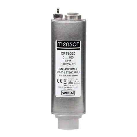
WIKA CPT6020 operating instructions

Clark Synthesis
Clark Synthesis TST329 datasheet
Baker Hughes
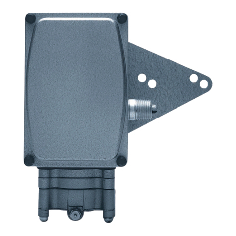
Baker Hughes Masoneilan 8000 instruction manual
S+S Regeltechnik
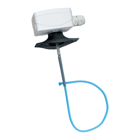
S+S Regeltechnik THERMASGARD MWTM-I Operating Instructions, Mounting & Installation
Sofraser
Sofraser 9000 Technical manual

HBM
HBM T32 FNA operating manual
