Sofraser 9000 User manual

Technical Manual
Viscosity and temperature
blind transducer
(to drive one MIVI sensor)
9000
Original version
REF.: 381/2

9000 Technical Manual
REF.: 381/2 2
IMPORTANT
THE OFFSET ADJUSTMENT IN THE AIR MUST
BE THE FIRST TASK COMPLETED.
clean and dry the ibrating rod of the iscometer in order to make it
neat and dry;
be sure the process is empty. The rod must be ibrating in the air;
install the sensor on the process and fix it with its 4 screws;
power on the de ice and wait 15 minutes;
The MIVI+9000 is a complete digital system that can only communicate with other
de ices through its serial RS-485 port. Hence, to make the zero adjustment in the air,
only a digital transmission through this port can be applied, it must be installed with its
9510 or 9710 accessory de ice, the zero adjustment in the air should be done on the
9510/9710 de ice (see 9510/9710 technical manual deli ered with the unit).

9000 Technical Manual
REF.: 381/2 3
TABLE OF CONTENT
1 TRANSDUCER PRINCIPLE.........................................................................................................4
2 TRANSDUCER TECHNICAL CHARACTERISTICS.....................................................................5
2.1 DIN-
RAIL
M
OUNTED ENCLOSURE
..............................................................................................5
2.1.1 Mechanical characteristics..............................................................................................5
2.1.2 Safety considerations......................................................................................................5
2.1.3 System connexion ..........................................................................................................6
2.2 IP67
E
NCLOSURE
....................................................................................................................7
2.2.1 Mechanical characteristics..............................................................................................7
2.2.2 Safety considerations......................................................................................................8
2.2.3 System connexion ..........................................................................................................8
3 ACCESSORY DEVICES.............................................................................................................10
3.1 9510 ....................................................................................................................................10

9000 Technical Manual
REF.: 381/2 4
1Transducer principle
The measuring chain is composed of three inseparable elements: the sensor, its cable and the
9000 transducer that controls it. The sensor cannot be used with another transducer or another cable
type or length because they are all a part of the resonant loop so they are matched together as one
ibrating system. The MIVI+9000 is specially designed to be used with Sofraser HMI/PLC accessories
(see chapter 3).
The acti e part of the sensor is composed of a ibrating rod held in oscillation at resonance fre-
quency by dri ing magnets. When the rod is immersed into a iscous material, the amplitude of the
ibration is dampened. The ibration amplitude aries according to the product iscosity where the
rod is immersed.
The sensor recei ing coil detects the response and the signal is con erted to a iscosity alue
through the electronic de ice. The factory calibration is performed with standard oils.
The transducer acquires the coils’ amplitudes and frequency and generates arious signals.
These signals represent the properties being measured. It is also in charge of powering the whole
system. It gi es iscosity and temperature information through the serial communication.
9000 Technical Manual
REF.: 381/2 5
2Transducer technical characteristics
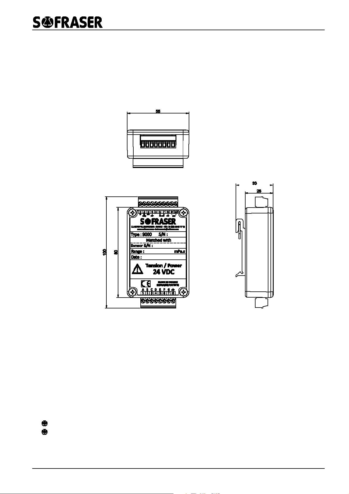
2.1 DIN-rail Mounted enclosure
2.1.1 Mechanical characteristics
Hereunder are the different iews of the electronics.
The processor must be connected to a stabilized and filtered 24 VDC (± 2.4 VDC) power supply.
The polarity of the power supply is highly important, in order to a oid any damage on the elec-
tronic board.
The operating temperature for this electronic de ice should be constant, the maximum is 50°C.
The electronic de ice deli ers the iscosity and temperature information to the selected HMI
through the serial RS-485 communication port.
2.1.2 Safety considerations
Do not touch wires while the processor is ON.
Do not connect either the “Neutral” or “Line” signal of the 110/220VAC to the de ice’s 0V pin.

9000 Technical Manual
REF.: 381/2 6
In the e ent of oltage fluctuations or non-conformity to oltage power supply specifications,
connect the de ice to a filtered and stabilized power supply.
Double-check all wiring before turning on the power supply.
Install at maximum distance from high- oltage cables and power equipment.
To maximize the system performances, a oid electromagnetic interferences by mounting the
processor on a metal panel and earthing the power supply.
2.1.3 System connexion
Only the link between the sensor and the terminal block has to be operated by the user accord-
ing to the following description.
1
2
3
4
5
6
7
8
9
10
RS 485 (B)
RS 485 (A)
Earth
0 V
+24 VDC
Sensor (A)
Sensor (B)
Sensor (C)
Sensor (D)
Pt100 (E)
Pt100 (F)
Pt100 (G)
Earth
1 2 3 4 5 6 7 8
The wires at the end of the cable ha e the following allocations.
wire colour item
transducer
te
r-
minal block
A blue receiving coil 1
B brown 2
C transparent driving coil 3
D black 4
E red
Pt100
5
F
G
yellow
green
6
7
N/A metal Earth 8
Wiring done by Sofraser
Wiring to be done by the user
9000 Technical Manual
REF.: 381/2 7
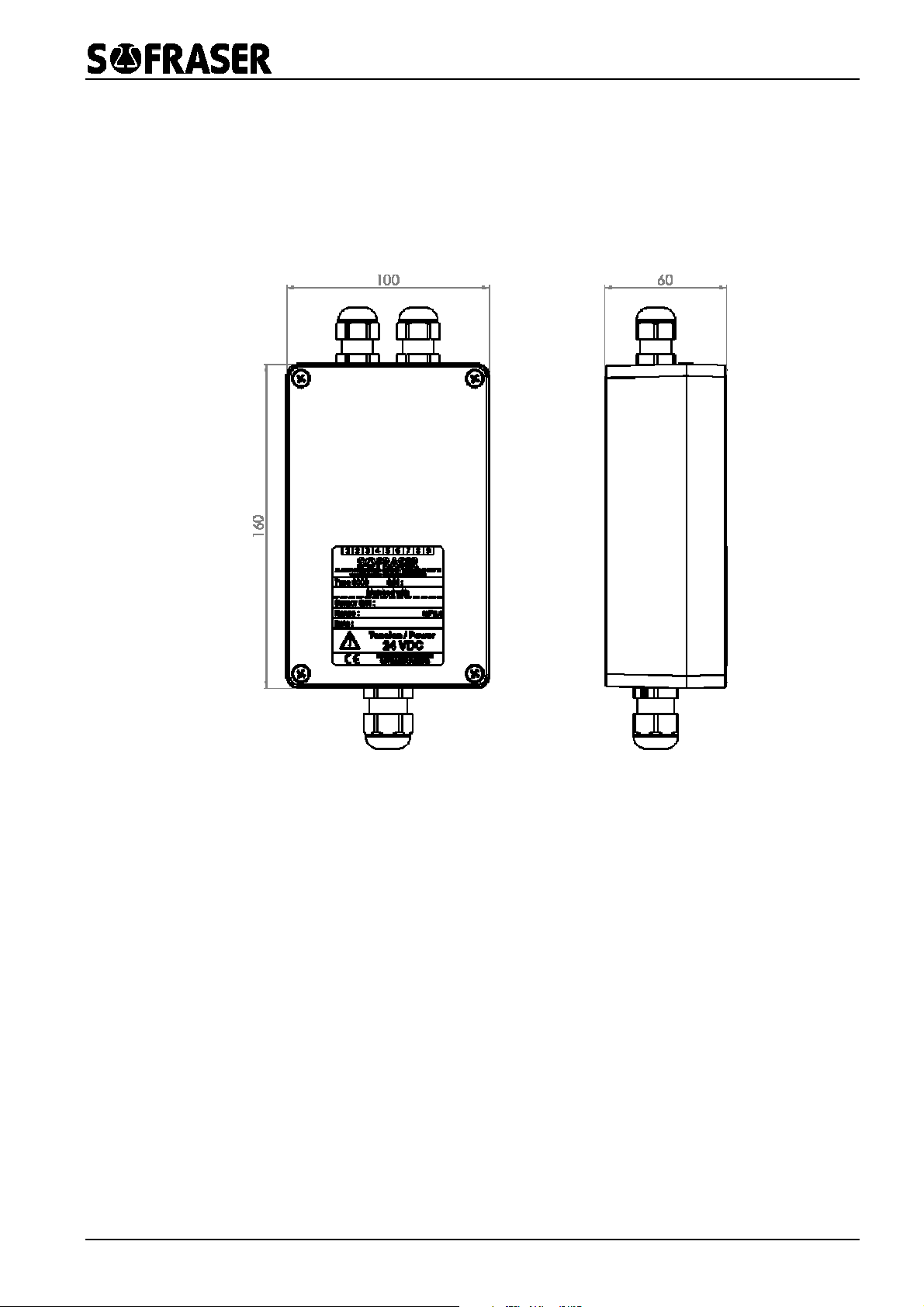
2.2 IP67 Enclosure
2.2.1 Mechanical characteristics
Hereunder are the different iews of the electronics.
The processor must be connected to a stabilized and filtered 24 VDC (± 2.4 VDC) power supply..
The polarity of the power supply is highly important, in order to a oid any damage on the elec-
tronic board.
The transducer box is IP67 and can be mounted on a panel or a plate through 4 screws.
The operating temperature for this electronic de ice should be constant, the maximum is 50°C.
This enclosure is equipped with 3 cable glands.
The electronic de ice deli ers the iscosity and temperature information to the selected HMI
through the serial RS-485 communication port.
9000 Technical Manual
REF.: 381/2 8
2.2.2 Safety considerations
Do not touch wires while the processor is ON.
Do not connect either the “Neutral” or “Line” signal of the 110/220VAC to the de ice’s 0V pin.
In the e ent of oltage fluctuations or non-conformity to oltage power supply specifications,
connect the de ice to a filtered and stabilized power supply.
Double-check all wiring before turning on the power supply.
Install at maximum distance from high- oltage cables and power equipment.
To maximize the system performances, a oid electromagnetic interferences by mounting the
processor on a metal panel and earthing the power supply.
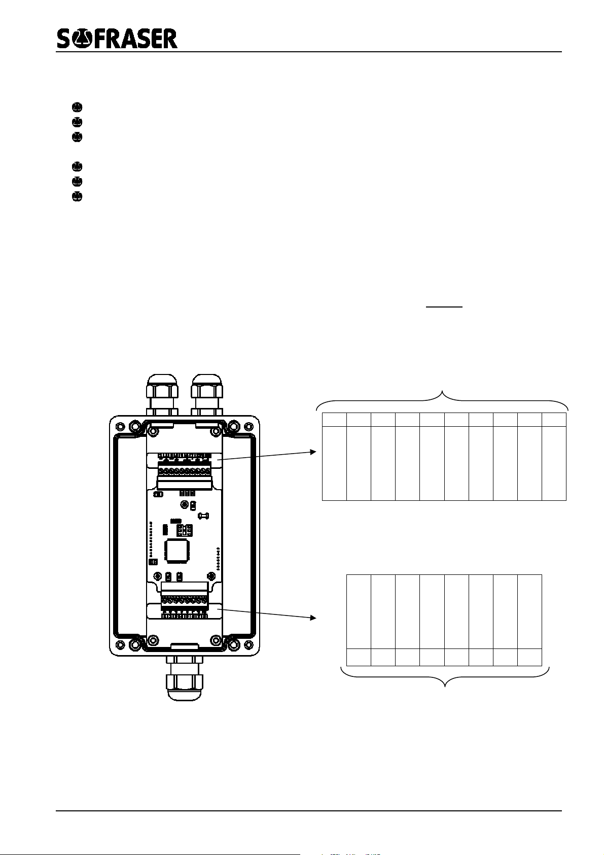
2.2.3 System connexion
All the connexions to the electronic de ice are made on the terminal block located inside the
blue enclosure.
All the wiring between the electronic boar an the terminal block are not to be touche .
Only the link between the sensor and the terminal block has to be operated by the user accord-
ing to the following description.
1
2
3
4
5
6
7
8
9
10
RS 485 (B)
RS 485 (A)
Earth
0 V
+24 VDC
Sensor (A)
Sensor (B)
Sensor (C)
Sensor (D)
Pt100 (E)
Pt100 (F)
Pt100 (G)
Earth
1 2 3 4 5 6 7 8
Wiring to be done by the user
Wiring done by Sofraser (DO NOT TOUCH)

9000 Technical Manual
REF.: 381/2 9
The wires at the end of the cable ha e the following allocations.
wire colour item
transducer te
r-
minal block
A blue receiving coil 1
B brown 2
C transparent driving coil 3
D black 4
E red
Pt100
5
F
G
yellow
green
6
7
N/A metal Earth 8
In case a cable gland is not used, this one has to be sealed with a cap.
9000 Technical Manual
REF.: 381/2 10
3Accessory devices
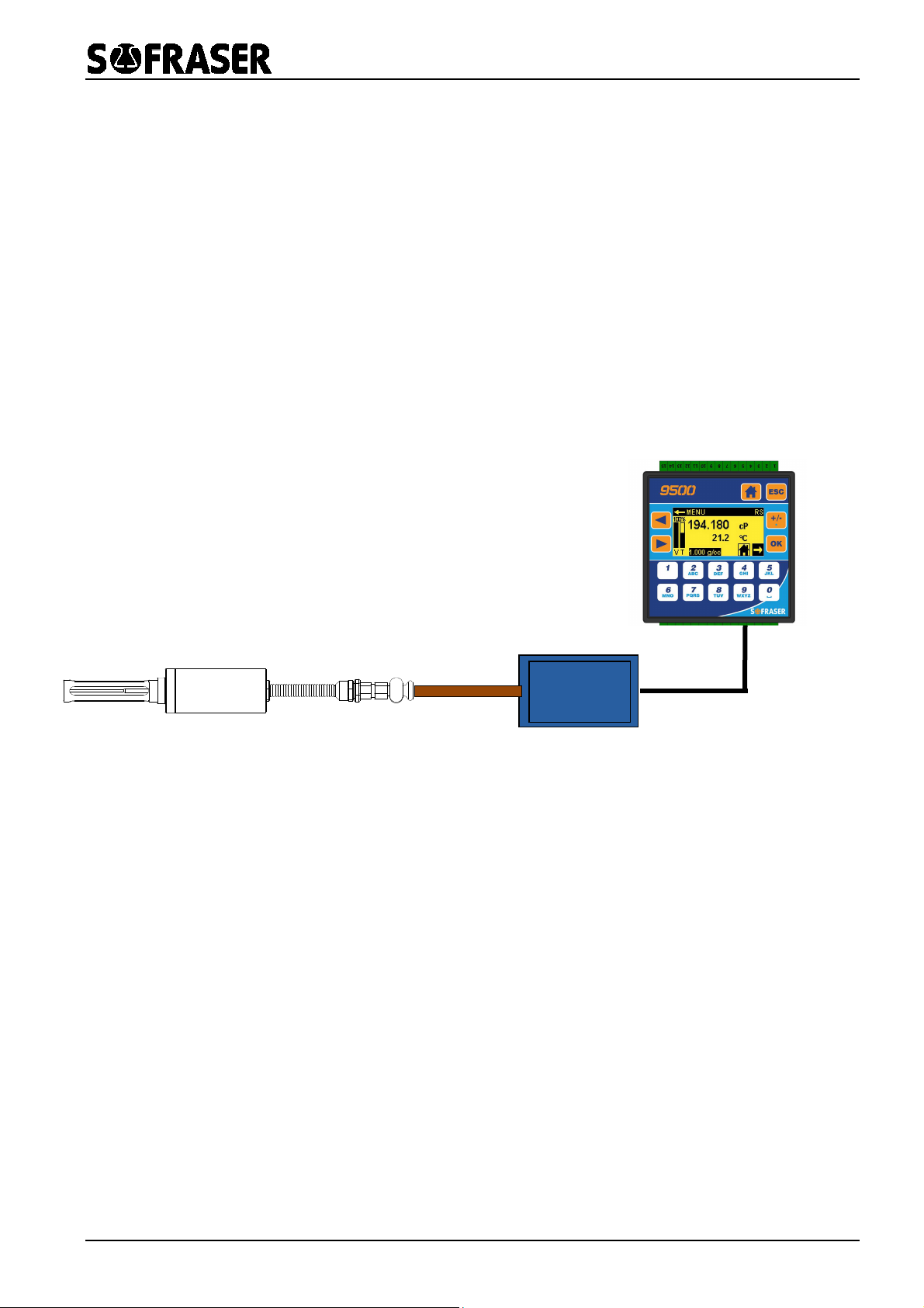
The 9510 and 9710 de ices ha e been designed as accessories to the MIVI+9000 sensor.
3.1 9510
The 9510 is an accessory controller that is to be connected to the 9000 transducer of the MIVI
sensor in order to add numerous functions to the whole system.
The 9510 electronic de ice has been designed in order to control 1 MIVI sensor. This means the
MIVI’s transducer 9000 and the 9510 are connected in a RS-485 serial loop as shown in the
scheme just abo e.
Trans ucer
9000
S/N
Other manuals for 9000
1
Table of contents
Other Sofraser Transducer manuals

Popular Transducer manuals by other brands


Industrial Controls
Industrial Controls IP Series Installation, operation and maintenance instructions

AERMEC
AERMEC NRA manual

FuehlerSysteme
FuehlerSysteme FS1580 operating manual

Balluff
Balluff Micropulse BTL5-A series user guide

Balluff
Balluff BTL7-A505-M Series Condensed guide

Simrad
Simrad ES333-7CD - REV A datasheet


