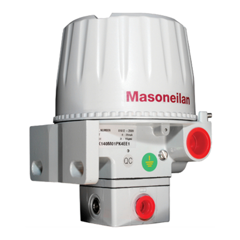
Baker Hughes Masoneilan 8000 User manual

Masoneilan™
8000 Models
Electro-pneumatic
Positioners and Transducers
ATEX Instruction Manual (Rev. A)
Baker Hughes Data Classification : Public

2 | Baker Hughes © 2021 Baker Hughes Company. All rights reserved.
Table of Contents
WARNING ........................................................................................................................................................... 4
1. Instrument Operation..................................................................................................................................... 5
1.1. The 8013 Model.......................................................................................................................................................5
1.2. The 8007 and 8008 Models.....................................................................................................................................5
2. Numbering System......................................................................................................................................... 5
3. Technical Specications................................................................................................................................ 7
3.1. Models 8007 and 8008 Transducers .......................................................................................................................7
3.2. Model 8013 Positioner .............................................................................................................................................7
3.3. Schematic ................................................................................................................................................................8
4. ATEX Intrinsic Safety Marking and Electrical Safety Parameters.............................................................. 8
4.1. Marking ....................................................................................................................................................................8
4.2. Electrical Safety Parameters ...................................................................................................................................9
5. ATEX Flameproof Marking and Electrical Safety Parameters .................................................................... 9
5.1. Marking ....................................................................................................................................................................9
5.2. Electrical Safety Parameter ...................................................................................................................................10
6. Electrical Characteristics............................................................................................................................. 10
6.1. Intrinsically safe apparatus ....................................................................................................................................10
6.2. Flameproof Apparatus ........................................................................................................................................... 11
7. Pneumatic Connections............................................................................................................................... 11
8. Electrical Connection, Installation and Start-Up ....................................................................................... 12
8.1. Conduit Entry in Flameproof Application................................................................................................................12
8.2. Electrical Connection .............................................................................................................................................13
8.3. Coil Wires Connection ...........................................................................................................................................13
8.4. Installation and Start-Up ........................................................................................................................................14
8.4.1. Installation....................................................................................................................................................14
8.4.2. Start-Up........................................................................................................................................................15
9. Transducer and Positioner Calibration ...................................................................................................... 15
9.1. 8007 or 8008 Transducer Calibration ....................................................................................................................16
9.2. 8013 Positioner Calibration ...................................................................................................................................16
10. Maintenance................................................................................................................................................ 17
11. Special Conditions of Work....................................................................................................................... 18
12. Special Conditions of Use ......................................................................................................................... 18
12.1. Common for Intrinsic Safety and Flameproof .....................................................................................................18
12.2. Intrinsically Safe Apparatus .................................................................................................................................19
12.3. Flameproof Apparatus: ........................................................................................................................................20
13. Complementary Documentation ............................................................................................................... 20

Masoneilan 8000 Models Positioners and Transducers ATEX Manual | 3
© 2021 Baker Hughes Company. All rights reserved.
THESE INSTRUCTIONS PROVIDE THE CUSTOMER/OPERATOR WITH IMPORTANT PROJECT-SPECIFIC
REFERENCE INFORMATION IN ADDITION TO THE CUSTOMER/OPERATOR’S NORMAL OPERATION
AND MAINTENANCE PROCEDURES. SINCE OPERATION AND MAINTENANCE PHILOSOPHIES VARY,
BAKER HUGHES COMPANY (AND ITS SUBSIDIARIES AND AFFILIATES) DOES NOT ATTEMPT TO
DICTATE SPECIFIC PROCEDURES, BUT TO PROVIDE BASIC LIMITATIONS AND REQUIREMENTS
CREATED BY THE TYPE OF EQUIPMENT PROVIDED.
THESE INSTRUCTIONS ASSUME THAT OPERATORS ALREADY HAVE A GENERAL UNDERSTANDING
OF THE REQUIREMENTS FOR SAFE OPERATION OF MECHANICAL AND ELECTRICAL EQUIPMENT
IN POTENTIALLY HAZARDOUS ENVIRONMENTS. THEREFORE, THESE INSTRUCTIONS SHOULD
BE INTERPRETED AND APPLIED IN CONJUNCTION WITH THE SAFETY RULES AND REGULATIONS
APPLICABLE AT THE SITE AND THE PARTICULAR REQUIREMENTS FOR OPERATION OF OTHER
EQUIPMENT AT THE SITE.
THESE INSTRUCTIONS DO NOT PURPORT TO COVER ALL DETAILS OR VARIATIONS IN EQUIPMENT
NOR TO PROVIDE FOR EVERY POSSIBLE CONTINGENCY TO BE MET IN CONNECTION WITH
INSTALLATION, OPERATION OR MAINTENANCE. SHOULD FURTHER INFORMATION BE DESIRED
OR SHOULD PARTICULAR PROBLEMS ARISE WHICH ARE NOT COVERED SUFFICIENTLY FOR THE
CUSTOMER/OPERATOR’S PURPOSES THE MATTER SHOULD BE REFERRED TO BAKER HUGHES.
THE RIGHTS, OBLIGATIONS AND LIABILITIES OF BAKER HUGHES AND THE CUSTOMER/OPERATOR
ARE STRICTLY LIMITED TO THOSE EXPRESSLY PROVIDED IN THE CONTRACT RELATING TO THE
SUPPLY OF THE EQUIPMENT. NO ADDITIONAL REPRESENTATIONS OR WARRANTIES BY BAKER
HUGHES REGARDING THE EQUIPMENT OR ITS USE ARE GIVEN OR IMPLIED BY THE ISSUE OF THESE
INSTRUCTIONS.
THESE INSTRUCTIONS ARE FURNISHED TO THE CUSTOMER/OPERATOR SOLELY TO ASSIST IN THE
INSTALLATION, TESTING, OPERATION, AND/OR MAINTENANCE OF THE EQUIPMENT DESCRIBED.
THIS DOCUMENT SHALL NOT BE REPRODUCED IN WHOLE OR IN PART WITHOUT THE WRITTEN
APPROVAL OF BAKER HUGHES.

4 | Baker Hughes © 2021 Baker Hughes Company. All rights reserved.
WARNING
BEFORE installing, using or carrying out any maintenance tasks associated with this instrument, READ
THE INSTRUCTIONS CAREFULLY.
These instruments comply with the essential safety requirements of the European Directive ATEX 2014/34/EU.
It is certified to be used in Gas or Dust explosive atmospheres, groups IIA, IIB, IIC, IIIA, IIIB and IIIC:
Category II 1GD – zones 0, 1, 2, 20, 21 and 22 for the protection mode “ia”
It is certified to be used in Gas or Dust explosive atmospheres, groups IIA, IIB+H2, IIIA, IIIB and IIIC:
Category II 2GD – zones 1, 2, 21 and 22 for the protection mode “d” and “tb”
Products certified as explosion proof equipment MUST BE:
a. Installed, put into service, used and maintained in compliance with European and/or national and local
regulations and in accordance with the recommendations contained in the relevant standards concerning
potentially explosive atmospheres.
b. Used only in situations that comply with the certication conditions shown in this document and after
verication of their compatibility with the zone of intended use and the permitted maximum ambient
temperature.
c. Installed, put into service and maintained by qualied and competent professionals who have undergone
suitable training for instrumentation used in areas with potentially explosive atmosphere. Such trainings are
not supported by Baker Hughes.
Note about Electro magnetic Compatibility:
These products fall under the scope of the Article 2.2.(d) of the EMC 2014/30/EU Directive. Consequently, this
Directive does not apply to these products.
It is the end user’s responsibility to:
• Verify material compatibility with the application
• Ensure proper use of fall protection when working at heights, per Safe Site Work Practices
• Ensure use of proper Personal Protective Equipment
• Take the appropriate actions to ensure that site personnel who are performing installation,
commissioning and maintenance have been trained in proper site procedures for working with and
around equipment, per Safe Site Work Practices
Baker Hughes reserves the right to discontinue manufacture of any product or change product materials, design,
or specifications without notice.
Under certain operating conditions, the use of damaged instruments could cause a degradation of the
performances of the system which may lead to personal injury or death.
Use only Masoneilan replacement parts to ensure that the products comply with the essential safety
requirements of the European Directives mentioned above.

Masoneilan 8000 Models Positioners and Transducers ATEX Manual | 5
© 2021 Baker Hughes Company. All rights reserved.
1. Instrument Operation
1.1. The 8013 Model
Electro-pneumatic positioner type 8013-.57 is generally coupled to a valve shaft. It controls the valve plug
position versus an input electrical analog signal.
1.2. The 8007 and 8008 Models
Model 8007-057 and 8008-057 electro-pneumatic transducers convert a low-power DC signal into a
proportional pneumatic signal in the 207 to 1035 mbar (3 to 15 psi), or 414 to 2070 mbar (6 to 30 psi) ranges,
as appropriated. Generally speaking, a signal from the Model 8007-057 is used by a pneumatic positioner or a
supply relay of the volume booster type. Model 8008-057 is fitted with a relay, which allows the transducer output
signal to directly control a valve pneumatic actuator.
2. Numbering System
• 8007 and 8008 electro-pneumatic Transducers :
a
Design
7 European model - without integrated relay
8 European model - with integrated relay
b
055 Weather-proof
057 Flameproof and Weather-proof (ATEX/IECEx)
058 Intrinsically safe and Weather-proof (ATEX/IECEx)
800 7
8 -
055
057
058

6 | Baker Hughes © 2021 Baker Hughes Company. All rights reserved.
2. Numbering System (cont.)
• 8013 Electro-pneumatic Positioner :
B
Design (type of mechanical feedback attached to the type of valve actuators)
0 37/38 and 87/88 actuators, without cam
1 37/38 and 87/88 actuators, basic cam
2 Camex™ II, multi-lobe cam
3 Sigma F, multi-lobe cam
4 Minitork™ II & 38002, multi-lobe cam
5 36000 Control Ball Valves, multi-lobe cam
6 HPBV, multi-lobe cam
7 Varipak™, basic cam
8 Varimax™, multi-lobe cam
d
55 Weather-proof
57 Flameproof and Weather-proof (ATEX/IECEx)
58 Intrinsically safe and Weather-proof (ATEX/IECEx)
8013
-
0
1
2
3
4
5
6
7
8
55
57
58

Masoneilan 8000 Models Positioners and Transducers ATEX Manual | 7
© 2021 Baker Hughes Company. All rights reserved.
3. Technical Specifications
3.1. Models 8007 and 8008 Transducers
• Input signal : 4-20 mA
• Hysteresis : 0.8 % of output range
• Linearity : ± 0.85% of output range
• Sensitivity : 0.5 % of input range
• Accuracy : ± 1.0 % of output range
• Housing electrical protection index : IP 65
• Maximum service temperature range : (refer also to the marking on the apparatus as some limitation may apply)
8007 : -20°C to +80°C and optional -55°C to +80°C
8008 : -20°C to +80°C
• Storage and transportation : -55°C to +90°C
• Air supply and output range
Transducer
PRESSURE in bar (psi)
Air supply Output signal range
8007 1.586 (23) 0.207 to 1.035 (3 to 15)
8008
1.586 (23) 0.207 to 1.035 (3 to 15)
2.413 (35) 0.414 to 2.068 (6 to 30)
3.2. Model 8013 Positioner
• Input signal : 4-20 mA
• Hysteresis : 0.8 % of output range
• Sensitivity : 0.3 % of input range
• Accuracy : ± 1.0 % of output range
• Housing electrical protection index : IP 65
• Maximum service temperature range : (refer also to the marking on the apparatus)
Standard instrument : -20°C to +80°C
Low temperature instrument : -55°C to +60°C
• Storage and transportation temperature : -55°C to +90°C
• Maximum air supply pressure : 5.20 bar (75 psi)

8 | Baker Hughes © 2021 Baker Hughes Company. All rights reserved.
3.3. Schematic
4. ATEX Intrinsic Safety Marking and Electrical Safety
Parameters
4.1. Marking
Name and address of the manufacturer
Dresser Produits Industriels S.A.S.
3 rue Saint-Pierre – CS40087
14110 CONDE SUR NOIREAU - FRANCE
Type designation
8007-058 or 8008-058 Electropneumatic transducers,
8013-▪58 Electropneumatic positioners, the “▪ “ can take the values from 0 to 9.
Basic and complementary marking
II 1 GD
Ex ia IIC T4 Ga Ta -55°C(1) to +80°C
Ex ia IIIC T135°C Da
Ex ia IIC T6 Ga Ta -55°C(1) to +40°C
Ex ia IIIC T85°C Da
1. The temperature can be limited to -20°C, depending of gasket material inside the pneumatic block.

Masoneilan 8000 Models Positioners and Transducers ATEX Manual | 9
© 2021 Baker Hughes Company. All rights reserved.
Serial number
Year of manufacturing
Number of notied body ▪▪▪▪
EC-Type examination certicate number
Warning
WARNING/AVERTISSEMENTS:
POTENTIAL DANGER OF ELECTROSTATIC DISCHARGES, SEE INSTRUCTIONS
4.2. Electrical Safety Parameters
The 8000 model is connected to a linear voltage source of a certied type for use in group IIC hazardous loca-
tions and its output circuit must be intrinsically safe approved per EN 60079-11.
Maximum input characteristics at terminal block:
Ui (V) Ii (A) Pi (W) Li (µH) Ci (nF)
28 0.1 0.7 0 0
5. ATEX Flameproof Marking and Electrical Safety
Parameters
5.1. Marking
Name and address of the manufacturer
Dresser Produits Industriels S.A.S.
3 rue Saint-Pierre 14 – CS40087
14110 CONDE SUR NOIREAU - FRANCE
Type designation
8007-057 or 8008-057 Electro-pneumatic transducers,
8013-▪57 Electro-pneumatic positioners, the “▪ “ can take the values from 0 to 9.
Basic and complementary marking
II 2 GD
Ex d IIB+H2 T6 Gb Ta –55°C(1), + 70° C
Ex tb IIIC T85°C Db IP65
Ex d IIB+H2 T5 Gb Ta –55°C(1), + 80° C
Ex tb IIIC T100°C Db IP65
1. The temperature can be limited to -20°C depending of gasket material inside the pneumatic block.

10 | Baker Hughes © 2021 Baker Hughes Company. All rights reserved.
5.1. Marking (cont.)
Serial number
Year of manufacturing
Number of notied body ▪▪▪▪
EC-Type examination certicate number
Warning
WARNING:
POTENTIAL DANGER OF ELECTROSTATIC DISCHARGES, SEE INSTRUCTIONS
DO NOT OPEN IF AN EXPLOSIBLE ATMOSPHERE MAY BE PRESENT
Cable temperature:
Must be mentioned if the temperature is greater than 70°C:
T Ambient T Cable
70°C 86°C
80°C 96°C
5.2. Electrical Safety Parameter
Maximum power dissipation : 2W
Input signal : 4-20mA
6. Electrical Characteristics
6.1. Intrinsically safe apparatus
• Signal : 4-20 mA,
• Input impedance : 216 Ohm,
• Coil : blue colour code, with 2 diodes.

Masoneilan 8000 Models Positioners and Transducers ATEX Manual | 11
© 2021 Baker Hughes Company. All rights reserved.
6.2. Flameproof Apparatus
• Signal : 4-20 mA,
• The table below lists all the circuits already developed.
Types of circuits
SIGNAL
mA
IMPEDANCE
Ohm
Colour code of
the coil
Code of the circuit
board
1-5 2753 RED 1
4-20 216 BLUE 4
4-20 1416 BLUE 5
4-20 726 BLUE 6
10-50 105 BLACK 7
10-50 105-205 BLACK 8
10-50 36-716 BLACK 9
3-15 924 RED 11
0-10 1001 YELLOW 12
0-20 173 BLUE 13
7-23 216-686 BLUE 14
15-150 94 BLUE 15
10-110 35-135 BLUE 16
0-10 701-2901 YELLOW 20
0-20 503 BLUE 21
0-20 248 BLUE 22
2-10 1000 YELLOW 23
7. Pneumatic Connections
• Make sure that the air supply pressure is suitable for the installation and for the instrument.
• When using a positioner, make sure that the air supply pressure matches the one specied on the
valve and positioner serial plates without exceeding 5.20 bar (75 psi).
If the instrument has been shipped alone, make pneumatic connections as per §3.3 :
- Air supply pressure to input (S),
- Output (O) to the actuator for the 8008 or 8013 or to the positioner for the 8007.
Minimum tubing diameter: 4 x 6 mm.
Remark: Tubing size must be in accordance with the actuator dimension.

12 | Baker Hughes © 2021 Baker Hughes Company. All rights reserved.
8. Electrical Connection, Installation and Start-Up
• Comply with current national and local regulations for electrical installation work.
• Must be installed and put into service in conformance with EN 60079-14 and / or national
and local regulations applicable for explosible atmospheres.
• Before carrying out any work on the device, power o the instrument or make sure the
local conditions are free of potentially explosive atmosphere for safe opening of the
cover.
• Connect the wires to the instrument terminals, taking care of complying with polarities,
maximum power dissipation allowed (2W), input signal (4-20mA).
• Before power up or after doing any work on the device, always check the cover is fully
screwed with the four screws (1). Screws up to surface contact then add ¼ to ½ turn
more.
Note: Before installation, check that the device is undamaged. In the event of damage, inform the
manufacturer whose address is shown on the serial plate.
8.1. Conduit Entry in Flameproof Application
The connections can be done with different variations taking into account approved manufacturer and requested
approvals:
A cable entry of a certied type Ex d IIC / Ex tb IIIC can be mounted directly on the single
1/2” NPT (ANSI/ASME B1.20.1) housing conduit connection or through the decompression device for
stainless steel ame arrestor option.
Decompression Device
In case an adaptor or reducer must be added, it must be apparatus certied ATEX (type Cooper CAPRI
CODEC).
The cable entry with or without its adaptor/reducer must be installed in conformance with the gure below:
Cable Gland Accessories Mounting on Instruments

Masoneilan 8000 Models Positioners and Transducers ATEX Manual | 13
© 2021 Baker Hughes Company. All rights reserved.
8.2. Electrical Connection
Connect the electrical cables to the terminal blocks located on the printed circuit board. Respect the polarities +
and – and the maximum power rating (2W) allowed.
Connect the device to the earth using the earth connections provided inside and outside of the device.
Basic rule for wiring:
• Must be used in addition to local regulation for electrical installation
• Connector slot approval:
• Insulation must be free of any damage along the wires inside the housing
• Tightening must be sucient to bring constant contact in time without being excessive to cut or damage
connection.
8.3. Coil Wires Connection
Instrument action is set by the appropriate connection of the coil wires.
Direct action: an increase of the signal results in an increase of the output pressure.
Reverse action: an increase of the signal results in a decrease of the output pressure.
Below picture gives the coil wires connection to the printed circuit board.
(*) Cross wires above the beam.
Correct Wiring Incorrect Wiring

14 | Baker Hughes © 2021 Baker Hughes Company. All rights reserved.
8.4. Installation and Start-Up
8.4.1.Installation
Note:
It is under the user responsibility to check the installation against Intrinsic safety rules taking into account
entity parameters of all devices in the loop in addition of temporary one like measurement devices.
For both installations, the measurement device representation is only for location information and not for
physical connections.

Masoneilan 8000 Models Positioners and Transducers ATEX Manual | 15
© 2021 Baker Hughes Company. All rights reserved.
8.4.2.Start-Up
Before power up or after doing any work on the device, always check the cover is fully screwed
with the four screws (1). Screws up to surface contact then add ¼ to ½ turn more.
Check that the cable gland is certied for the intended use and that the electrical data are suitable
for the operating zone.
Before start-up, proceed, if required, with instrument calibration as per §9 and/or ensure that all the safety
instructions in the preceding paragraphs have been strictly followed.
9. Transducer and Positioner Calibration
Before to power up the device and to proceed a calibration, carefully read the following safety warnings.
Comply with current national and local regulations for electrical installation work.
Must be installed and put into service in conformance with EN 60079-14 and/or national and local
regulations applicable for explosible atmospheres.
Before carrying out any work on the device, power o the instrument or make sure the local
conditions are free of potentially explosive atmosphere for safe opening of the cover.
Connect the wires to the instrument terminals, taking care of complying with polarities, maximum
power dissipation allowed (2W), input signal (4-20mA).
Before power up or after doing any work on the device, always check the cover is fully screwed
with the four screws (1). Screws up to surface contact then add ¼ to ½ turn more.
In any case, check that the installed nozzle (Ref 16) is suitable for the valve size, for the actuator and for the
instrument air supply pressure.

16 | Baker Hughes © 2021 Baker Hughes Company. All rights reserved.
9.1. 8007 or 8008 Transducer Calibration
Adjust the zero using the zero adjusting screw (balance spring) and span using the span adjusting screw (biasing
spring).
For further details, refer to the detailed instruction manual.
9.2. 8013 Positioner Calibration
When a valve is shipped with a positioner, it is factory calibrated. When shipped alone, the calibration will be
made as follows:
• Proceed with pneumatic and electrical connections as per §6 and §7
• Check the position of the balance spring (8) as a function of the actuator air action (see picture below)
• Loosen locknuts (7) and (11)
• Adjust the biasing spring (52) as to the valve is closed at the corresponding signal
• Adjust the balance spring (6) as to the valve fully strokes for the full input signal range
• Repeat the 2 above steps until the adjustment is correct
• Tighten locknuts (7) and (11)
• Strictly follow safety instructions under §8.4 before start-up

Masoneilan 8000 Models Positioners and Transducers ATEX Manual | 17
© 2021 Baker Hughes Company. All rights reserved.
10. Maintenance
Before carrying out any work on the device, power o the instrument or make sure the local
conditions are free of potentially explosive atmosphere for safe opening of the cover.
These operations must be done in conformance with EN 60079-17 and/or national and local
regulations applicable for explosible atmospheres.
Before power up or after doing any work on the device, always check the cover is fully screwed
with the four screws (1). Screws up to surface contact then add ¼ to ½ turn more.
Instruments installed in zones 20, 21 and 22 must be cleaned to prevent any dust build up on
the walls. See instruction §12.1 b & c for safe cleaning.
Check that no part of the transducer or positioner is damaged.
In the event of damage, replace the defective parts with genuine manufacturer’s replacement parts.
Pay particular attention to the following:
General condition of the housing.
Check the cable gland and the electrical connections.
Check the pilot (pneumatic relay):
Disconnect air supply and remove relay from the instrument
After disassembly of the relay (see picture below) clean parts and blow out ports and tubing.
Reassemble as shown below.
Check apper/nozzle arrangement :
Disconnect air supply
Loosen the screw (45) holding the apper to the beam
and remove the apper (46)
Unscrew the nozzle (16) from the case (14)
Clean the nozzle with solvent and blow out hole with
clean air
Reassemble all the parts.

18 | Baker Hughes © 2021 Baker Hughes Company. All rights reserved.
11. Special Conditions of Work
Based on 2014/34/EU directive, a training session must be followed by person usually recognized to use
apparatus in explosive atmospheres.
This training session is not supported by Dresser Produits Industriels S.A.S.
12. Special Conditions of Use
12.1.Common for Intrinsic Safety and Flameproof
a. It is under the user responsibility to check once a year the gasket and in the event of damage to replace the
defective parts with manufacturer’s replacement parts only.
b. For use in dusty hazardous areas, the user will have to proceed to regular cleaning of the dierent sides of the
enclosure to avoid the deposits of dusts, the maximum thickness must be <5 mm. This cleaning will be done
using recommendations dened in §c.
For safe operation, this can be done only if the local conditions around the device are free of
potentially explosive atmosphere.
c. To avoid the risk of ignition from electrostatic discharge, it shall be necessary to follow the guidance of EN
60079-32-1, for example to clean the device with a wet rag.
It is recommended for safe operation, that the local conditions around the device are free of potentially
explosive atmosphere.
d. The user will have to check the temperature increase on the Model 8000 Series coming from the mechanical
part in contact with the 8000 housing or through the process thermal radiation be less or equal than the
temperature classication allowed. This must be done in conformance with EN 60079-14 and/or national and
local regulations applicable for explosible atmospheres.
e. This requirement is only applicable for multi protection marking. During the 8000 Series positioner installation
on site, the nal user must show the protection mode used on the serial plate removing the tears o tabs or
putting a cross in the dedicated area. The label below is shown for example only and is not representative to
the 8000 Series positioner label.

Masoneilan 8000 Models Positioners and Transducers ATEX Manual | 19
© 2021 Baker Hughes Company. All rights reserved.
12.2. Intrinsically Safe Apparatus
• The cable gland must have a protection level at least equal to IP65 according to EN 60529 standards and
with a type certied for the protection mode Ex ia gas and dust. It must be compatible with the minimum
temperature written on the serial plate.
• For the 8000 Series housing in aluminum material, the user will have to determine the use of the device for
group II category 1 (zone 0) against potential inammable source causing by sparks in the event of impact or
friction.
• The voltage supply connected on 8000 Series input connectors must be certied for use in group IIC and the
loop intrinsic safety approved. The entity parameters of the voltage supply must be compatible with the entity
parameters of the 8000 Series described §4.2.

20 | Baker Hughes © 2021 Baker Hughes Company. All rights reserved.
12.3. Flameproof Apparatus:
• The four cover screws (1) must be
CHC M6-25
Screw head conforms to ISO 4762
A 4-80 (ISO 3506) property class only.
Machining quality 6g/6H based on ISO 262 and ISO 965-1&3.
• For Models 8007 & 8008: in case of magnet adjustment for pressure output calibration, the 3/8” NPT plug on
the back of the case must be completely screwed and tighten with at least four threads fully engaged. This plug
can be replaced by a certied Ex d and Ex tb apparatus.
• The cable entry must have a protection level at least equal to IP65 according to EN 60529 standards.
• For temperatures greater than 70°C, the user must choose a cable entry and a cable compatible with:
Ambient Temperature Cable Temperature
70°C 86°C
80°C 96°C
• When the ambient temperature is lower than -20°C, the user will have to choose a cable entry and a cable
compatible with the ambient temperature specied on the marking plate. The minimum temperature can go
down -55°C.
• Use only the following greases for the explosion-proof joints, shaft, threads, cable gland:
Grease Type Manufacturer
GRAPHENE 702 ORAPI
MOLYKOTE 111 COMPOUND MOLYKOTE®
MULTILUB MOLYKOTE®
GRIPCOTT NF MOLYDAL
• The width of the ameproof joints is dierent from the values specied in the tables of the standard EN/IEC
60079-1.
13. Complementary Documentation
Each apparatus is shipped with an ATEX Instruction Manual. This document is as a minimum a copy of this
document. It is available in all official languages of the European Union Countries.
This manual suits for next models
3
Table of contents
Other Baker Hughes Transducer manuals
Popular Transducer manuals by other brands

Evco
Evco EVHP523 instruction sheet

RS PRO
RS PRO ICA32N instruction manual

S+S Regeltechnik
S+S Regeltechnik PHOTASGARD FSHKM Operating Instructions, Mounting & Installation

Fairchild
Fairchild T6100 Installation, operation and maintenance instructions

HyQuest Solutions
HyQuest Solutions WL3100 instruction manual

Panametrics
Panametrics T5 installation guide