manuals.online logo
Brands
  1. Home
  2. •
  3. Brands
  4. •
  5. Aetechron
  6. •
  7. Amplifier
  8. •
  9. Aetechron 7548 User manual

Aetechron 7548 User manual

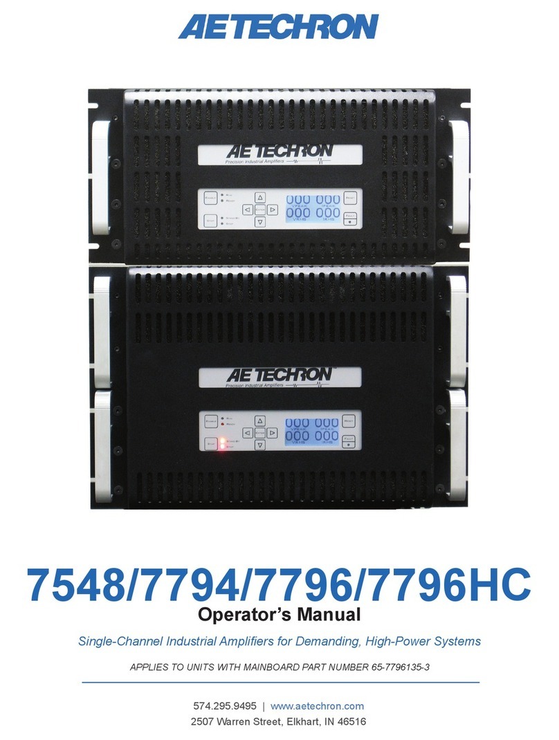
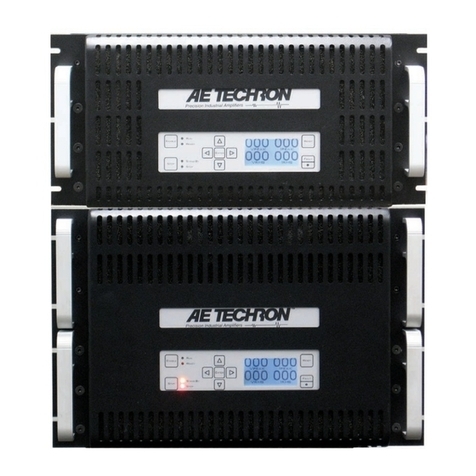
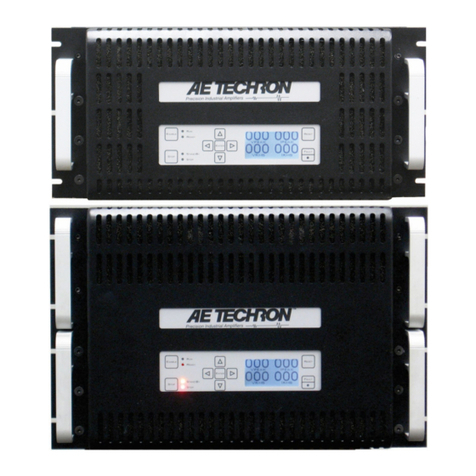
CONGRATULATIONS on your
purchase of the 7548/7796 AE Techron power amplifier—
a single-channel industrial amplifier designed for use in the
most demanding high-power systems. AE Techron amplifiers
are built and tested to the most stringent quality standards
for long life and outstanding performance. The AE Techron
brand is known through the world for its robust precision
amplifiers, as well as its product service and support.
The 7548/7796, when operated in Controlled Voltage
mode, provides precision amplification at frequencies from
DC to 50 kHz at full power and DC to 100 kHz at reduced
power, with low harmonic and intermodulation distortion
and low noise. The 7548/7796 operates on a 208-volt
(optional 400-volt) 3-phase AC mains.
Features
ŸDC-enabled, four quadrant amplifier.
ŸStandard SIM (Specialized Input Module) features
unbalanced BNC, balanced Phoenix-type 3-pin input,
and 25-pin Interlock – I/O connectors.
ŸBuilt-in protection circuitry safely provides for
sustained, full-power output. Full protection includes:
Over-Voltage, Over-Temperature, temperature monitor
of heat-sinks, transformers and output transistors,
and immediate protection and fast recovery in the
event of overheating.
ŸGenerous, front-to-back cooling allows tight rack
mounting without the need for air spaces and permits
longer run times at higher duty cycles.
ŸSwitching, bi-level power supply adapts to meet
demands for high voltage or high current.
7548/7796
QUICK START
www.aetechron.com
Advanced Test Equipment Rentals
www.atecorp.com 800-404-ATEC (2832)
®
E
s
t
a
b
l
i
s
h
e
d
1
9
8
1
Never attempt to lift
the amplifier
without assistance.
Crushing bodily
injury can result if
care is not taken
during installation.
If product is rack-
mounted, cabinet
may overturn if not
secure.
1 UNPACKING
2 CHECK CONTENTS
3 MOUNTING/INSTALLATION
4 COOLING
Carefully unpack your amplifier from the carton and
visually inspect the amplifier for damage. All amplifiers
are tested and inspected for damage before leaving the
factory, so if any damage is found, please notify the
shipping company immediately. Save the shipping
carton and materials as evidence of damage.
In addition to the 7548 or 7796 amplifier, your carton
should contain the following:
1. NEMA connector for power cord
2. 7548/7796 Operator's Guide CD and Quick Start
sheet
Use the rack “ears” located on each side of the front
panel to mount the amplifier to a standard EIA (Electronic
Industries Association) rack. Use standard rack mounting
hardware to mount the amplifier.
The 7548 weighs
approximately 103
pounds, and the 7796
weighs approximately
153 pounds. Be sure
this weight is properly
supported by using
rack supports at both
front and rear of the
amplifier and by using
all the screw
locations.
Optionally, the
amplifier can be
placed on a
bench top. To
protect surfaces,
use rubber feet
included in the
toolkit.
When amplifier is rack-
mounted, the sidewalls of
the rack must be at least
2 in. (5.1 cm) away from
the chassis, and the back
of the rack should be at
least 4 in. (10.2 cm) from
the chassis.
Cooling capacity required is 300 ft3/min. total per amp.
Allow for hot air discharge through the amplifier’s rear
grill or vented rear door, and provide a source of cool air
for fan intakes. If rack ventilation is poor, use a vent tube
to the outside of the rack. If operating while in a dusty
environment, use commercial furnace filters to prevent
rapid clogging of the filters on the amplifier.
DANGER
The risk of lethal ELECTRICAL
SHOCK exists when connecting
AC mains! Disconnect the
source before connecting AC
power wires to the connector.
5 CONNECTIONS
B. Output Wiring
A. Select Mode of Operation
Connect the input signal to the amplifier through the SIM-
BNC Specialized Input Module. Connect using Unbalanced
BNC or Balanced Phoenix connectors. Input cables should
be high quality and shielded for minimal noise and
possible feedback.
Connect the amplifier to
the proper 3-phase AC
mains using the NEMA-
style locking AC
connector (included).
1. Connect negative
terminal of the load
to the SAMPLED
COMMON terminal.
2. Connect the load’s
positive terminal to
the amplifier’s
OUTPUT terminal.
C. Input Wiring
D. AC Supply
Note: the 7548/7796 amplifier ships from the factory
configured to operate in CONTROLLED VOLTAGE mode. For
setup instructions for operation in CONTROLLED CURRENT
mode, please see the product Operator’s Manual.
CONTROLLED VOLTAGE: The amplifier will provide an
output voltage that is constant and proportional to the
control (input) voltage. Use this mode if you want the
output voltage waveform to be like the input waveform.
CONTROLLED CURRENT:
The amplifier will provide an output current that is
constant and proportional to the control (input) voltage.
Use this mode if you want the output current waveform to
be like the input waveform.
ELECTRIC SHOCK HAZARD.
Output potentials can
be lethal. Make
connection only with amplifier
disconnected from AC Power and
input signals removed.
Connect your load
across the 4-position
terminal barrier block
output connector using
up to #4 AWG wire.
Always use the
WARNING: A factory-installed
resistor connects the terminals
marked “SAMPLES COMMON”
and “CHASSIS GROUND.” DO NOT
remove this resistor except for
special, multi-amp applications.
If resistor is removed, dangerous
output and/or damage to the
load may result.
appropriate wire size and insulation for the maximum
current and voltage expected at the output. Never connect
the output of the amplifier to any other model amplifier,
power supply, signal source or other inappropriate load;
fire can result.
Never use shielded cable for
output wiring.
Refer to the balanced and unbalanced pin connector
illustrations for cable wiring. NOTE: Custom wiring should
only be performed by qualified personnel.
6 STARTUP PROCEDURE
1. Turn down the level of your signal source.
2. Check to make sure the AC Mains Switch/Circuit
Breaker is in the off position (DOWN).
5. Adjust the level of your input signal source to achieve
the desired output level.
3. Apply AC power to the amplifier.
6. Use the Navigation Buttons to navigate through the
various voltage and current measurement functions on
the LCD display.
4. Move the AC Mains Switch/Circuit Breaker to the on
position (UP) to turn the amplifier ON. Wait for the
yellow READY and green RUN LEDs to illuminate.

Other manuals for 7548

1

This manual suits for next models

1

Other Aetechron Amplifier manuals

Aetechron 7000-Series User manual

Aetechron

Aetechron 7000-Series User manual

Aetechron 7220 Series User manual

Aetechron

Aetechron 7220 Series User manual

Aetechron 7548 User manual

Aetechron

Aetechron 7548 User manual

Aetechron 2110 User manual

Aetechron

Aetechron 2110 User manual

Aetechron 8101 User manual

Aetechron

Aetechron 8101 User manual

Aetechron 8704 User manual

Aetechron

Aetechron 8704 User manual

Aetechron 8500 Series User manual

Aetechron

Aetechron 8500 Series User manual

Aetechron 7228 User manual

Aetechron

Aetechron 7228 User manual

Aetechron 2100 series User manual

Aetechron

Aetechron 2100 series User manual

Aetechron 7800 Series User manual

Aetechron

Aetechron 7800 Series User manual

Aetechron 8500 Series User manual

Aetechron

Aetechron 8500 Series User manual

Aetechron 8302 User manual

Aetechron

Aetechron 8302 User manual

Aetechron 2105 User manual

Aetechron

Aetechron 2105 User manual

Aetechron 7224 User manual

Aetechron

Aetechron 7224 User manual

Aetechron 7224 User manual

Aetechron

Aetechron 7224 User manual

Aetechron LVC 5050 User manual

Aetechron

Aetechron LVC 5050 User manual

Aetechron 7212 User manual

Aetechron

Aetechron 7212 User manual

Aetechron 8504 User manual

Aetechron

Aetechron 8504 User manual

Aetechron 7114 User manual

Aetechron

Aetechron 7114 User manual

Aetechron 7224 User manual

Aetechron

Aetechron 7224 User manual

Aetechron 7548 User manual

Aetechron

Aetechron 7548 User manual

Aetechron LV 3620 User manual

Aetechron

Aetechron LV 3620 User manual

Aetechron 7548RLY User manual

Aetechron

Aetechron 7548RLY User manual

Aetechron LVC5050RLY Owner's manual

Aetechron

Aetechron LVC5050RLY Owner's manual

Popular Amplifier manuals by other brands

K.M.E. DA 230 user manual

K.M.E.

K.M.E. DA 230 user manual

DJ-Tech iVisa 500 BT user manual

DJ-Tech

DJ-Tech iVisa 500 BT user manual

Balanced Audio Technology VK-20 owner's manual

Balanced Audio Technology

Balanced Audio Technology VK-20 owner's manual

Kicker Warhorse WX 10000-1 owner's manual

Kicker

Kicker Warhorse WX 10000-1 owner's manual

PrimaLuna EvoLution Series manual

PrimaLuna

PrimaLuna EvoLution Series manual

AXESS ELECTRONICS AC8 quick guide

AXESS ELECTRONICS

AXESS ELECTRONICS AC8 quick guide

Trafomatic Audio Experience Elegnce user manual

Trafomatic Audio

Trafomatic Audio Experience Elegnce user manual

Trafomatic Audio Premise user manual

Trafomatic Audio

Trafomatic Audio Premise user manual

OSD Audio MX 880 owner's manual

OSD Audio

OSD Audio MX 880 owner's manual

AUDAC DPA74 User manual & installation guide

AUDAC

AUDAC DPA74 User manual & installation guide

Crown 460 CSL Service manual

Crown

Crown 460 CSL Service manual

Crown XTi 2002 Operation manual

Crown

Crown XTi 2002 Operation manual

Adastra PA5120RD Operation manual

Adastra

Adastra PA5120RD Operation manual

Toa 9000M2 Series user guide

Toa

Toa 9000M2 Series user guide

Sarno Music Solutions V8-B owner's manual

Sarno Music Solutions

Sarno Music Solutions V8-B owner's manual

Pioneer M-91 Service manual

Pioneer

Pioneer M-91 Service manual

OPTILAB EDFA-MP-MSA user manual

OPTILAB

OPTILAB EDFA-MP-MSA user manual

JDS Labs The Element operating instructions

JDS Labs

JDS Labs The Element operating instructions

manuals.online logo
manuals.online logoBrands
  • About & Mission
  • Contact us
  • Privacy Policy
  • Terms and Conditions

Copyright 2025 Manuals.Online. All Rights Reserved.