Aewin MB-8301A-Q24 User manual
AEWIN Technologies Co., Ltd MB-8300 User Man al
1
User Manual
Ver. Release Date Update
1.0V 2013.11.19 Release
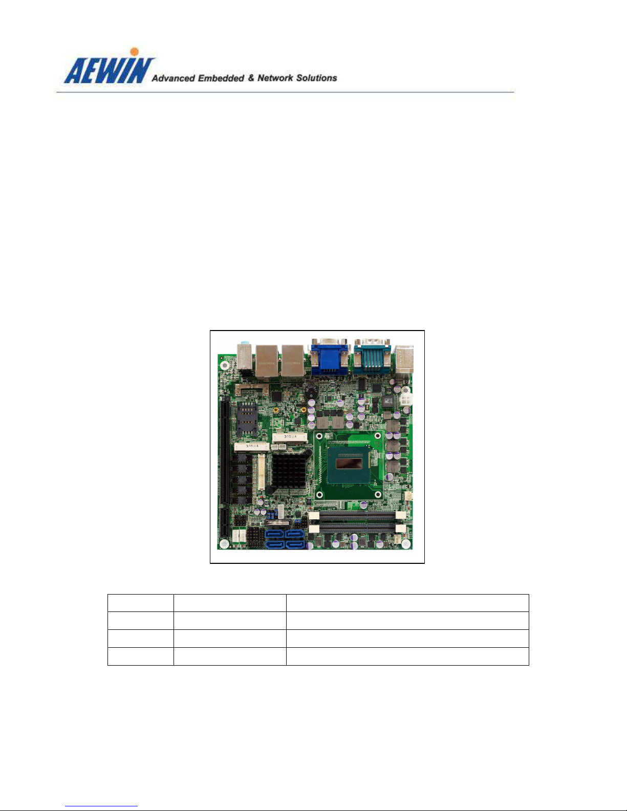
MB-8301
Mini-ITX with onboard Intel® 4th generation Core™ i7/i5/i3/Celeron Mobile
processor, Intel® QM87 chipset, DDR3 p to 16GB, 2 x Intel® Giga LAN,
HDMI, DVI, VGA & LVDS, 4 x SATA, 10 x USB, 6 x COM, GPIO, HD A dio,
PCI-Express X16 & X1 slots, 2 x Mini-PCIe, DC 8V ~ 32V inp t

AEWIN Technologies Co., Ltd MB-8300 User Man al
2
Copyright
Trademark
Limitation of liability
The content of this document and software with this product are copyrighted by
AEWIN technologies Co., Ltd,
This document contains proprietary information protected by copyright. All rights are
reserved; no part of this manual may be reproduced, copied, translated or transmitted
in any form or by any means without prior written permission of the manufacturer.
The content of this document is intended to be accurate and reliable; the original
manufacturer assumes no responsibility for any inaccuracies that may be contained in
this manual. The original manufacturer reserves the right to make improvements to the
products described in this manual at any time without prior notice
All other product names mentioned herein are used for identification purpose only and
may be trademarks and/or registered trademarks of their respective companies
While reasonable efforts have been made to ensure the accuracy of this document,
the manufacturer and distributor assume no liability resulting from errors or omissions
in this document, or from the use of the information contained herein.
For more information or other AEWIN products, please visit our website
http://www.aewin.com.tw.
For technical supports, please send your inquiry to sales@aewin.com.tw

AEWIN Technologies Co., Ltd MB-8300 User Man al
3
acking list
Before use this product, please make sure that the following materials have been shipped.
1 x MB-8301 board
1 x SATA cable, L/ 200mm
1 x 12V/5V SATApower cable , L/ 150mm
1 x CPU cooling Fan
1 x CD Driver Utility
( p/n: 46L-SATA11-00 )
( p/n: 46L-IPOW41-00 )
( p/n: 49L-F00050-00 )
* If any of those items are missing or damaged, please contact with sales representative or distributor
p/n: 46L-SATA11-00
p/n: 46L-IPOW41-00
p/n: 49L-F00050-00
Model Name Description
MB-8301A-Q24 Mini-ITX w/ i7-4700EQ, 2 GLAN,HDMI/DVI/VGA/LVDS, COM, USB,
Mini-PCIe socket, 4 SATA, 8V ~ 32V DC input, PCIe X16 slot
MB-8301A-D27 Mini-ITX w/ i5-4400E , 2 GLAN,HDMI/DVI/VGA/LVDS, COM, USB,
Mini-PCIe socket, 4 SATA, 8V ~ 32V DC input, PCIe X16 slot
MB-8301A-D24 Mini-ITX w/ i3-4100E , 2 GLAN,HDMI/DVI/VGA/LVDS, COM, USB,
Mini-PCIe socket, 4 SATA, 8V ~ 32V DC input, PCIe X16 slot
MB-8301A-D22 Mini-ITX w/ Celeron 2000E , 2 GLAN,HDMI/DVI/VGA/LVDS, COM
Mini-PCIe socket, 4 SATA, 8V ~ 32V DC input, PCIe X16 slot
MB-8301B-Q24 Same as MB-830A-Q24, but come with, PCIe X16 & PCIe X1 slots
MB-8301B-D27 Same as MB-830A-D27, but come with, PCIe X16 & PCIe X1 slots
MB-8301B-D24 Same as MB-830A-D24, but come with, PCIe X16 & PCIe X1 slots
MB-8301B-D22 Same as MB-830A-D22, but come with, PCIe X16 & PCIe X1 slots
AEWIN Technologies Co., Ltd MB-8300 User Man al
4
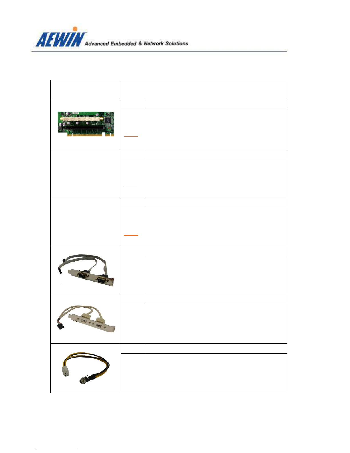
Optional Accessory
Photo Model Name
P/N:
RE-S01
PCIe riser card support 1 x PCIe X16 & 1 x PCI slots
Note: Work with MB-8301B Series only
P/N:
RE-S02
PCIe riser card support 2 x PCI slots
Note: Work with MB-8301B Series only
P/N:
RE-S03
PCIe riser card support 1 x PCIe X16 & 1 x PCIe X1 slots
Note: Work with MB-8301B Series only
P/N:
46L-ICOM38-00
Dual D-Sub 9-pin COM port card, L/ 250mm, with bracket
P/N:
46L-IUSB07-AA
Dual USB cable, L/ 250mm, with bracket
P/N:
46L-IPOW102-00
P4 4-pin to DC Jack lockable power cable, L/ 200mm

AEWIN Technologies Co., Ltd MB-8300 User Man al
5
Safety Information
Operation Safety
To prevent electrical shock hazard, disconnect the power cable from the electrical
outlet before relocating the system.
When adding or removing devices to or from the system, ensure that the power
cables for the devices are unplugged before the signal cables are connected. If
possible, disconnect all power cables from the existing system before you add a
device.
Before connecting or removing signal cables from the motherboard, ensure that all
power cables are unplugged.
Seek professional assistance before using an adapter or extension cord. These
devices could interrupt the grounding circuit.
Make sure that your power supply is set to the correct voltage in your area.
If you are not sure about the voltage of the electrical outlet you are using, contact
your local power company.
If the power supply is broken, do not try to fix it by yourself. Contact a qualified
service technician or your retailer.
Before installing the motherboard and adding devices on it, carefully read all the
manuals that came with the package.
Before using the product, make sure all cables are correctly connected and the
power cables are not damaged. If you detect any damage, contact your dealer
immediately.
To avoid short circuits, keep paper clips, screws, and staples away from connectors,
slots, sockets and circuitry.
Avoid dust, humidity, and temperature extremes. Do not place the product in any
area where it may become wet.
Place the product on a stable surface.
If you encounter technical problems with the product, contact a qualified service
technician or your retailer.

AEWIN Technologies Co., Ltd MB-8300 User Man al
6
Contents
Chapter 1
General Information ……………………………………….5
1.1 Introduction …………………………………………..……………………...8
1.2 Specification …………………………………………………..………..…...9
1.3 Block Diagram …………………………………………….…….….............11
1.4 Board layout Dimension ……………………………………….……………..12
1.5 IO / Connector ………………………………………………………………….14
Hardware installation …………………………………….16
2.1 The location of onboard connectors ..………………..………………….16
2.2 The location of onboard jumpers ………………………………………...18
2.3 The function list of onboard jumpers setting ……………………………19
2.3.1 JP1 for Clean CMOS jumper ……………………………………….…...19
2.3.2 JP3 for Power AT/ATX mode selection …………………………..……20
2.3.3 JP4 for LVDS voltage select ………………………………………..……21
2.3.4 JP4 for LVDS brightness control mode..…………………………..……22
2.4 The pin define of onboard pin header ………………………….……......23
2.4.1 CN1 for Low Pin Count pin-header …………………………..…...........23
2.4.2 CN4 for 8-bit GPIO pin header ………..…….…………………..….......24
2.4.3 CN5 & CN6 for DC out for HDD power …………………………........25
2.4.4 CN7 & CN8 for USB2.0 pin-header ………………........……………..26
2.4.5 CN9 & CN10 for SATA 3.0/2.0 connector ………………………………27
2.4.6 CN11 for SPI programmer pin-heder ……………................................. 28
2.4.7 CN12 for PCI-Express X1 slot...............................................................29
2.4.8 CN14 for COM4, RS232 pin-header ......................................................30
2.4.9 CN16 for front panel pin-header .......................................... 31
2.4.10 CN19 for COM3, RS232 pin-header .......................................................32
2.4.11 CN21 for COM2, RS232/422/485 …………......................................... 33
2.4.12 CN22 for Half-size Mini-PCIe WLAN LED indictor ..................................35
2.4.13 CN23 for Full-size Mini-PCIe WLAN LED indictor................................... 36
2.4.14 CN25 for Full-size Mini-PCIe socket ......................................................37
Chapter 2

AEWIN Technologies Co., Ltd MB-8300 User Man al
7
Chapter 3
rogramming WDT & G IO ………………………..47
3.1 GPIO DOS sample code ............……………………..……………...…..…47
3.2 WatchDog timer DOS sample code .…………………… ..……….…..…...54
2.4.15 CN26 for Half-size Mini-PCIe sockets ......................................................38
2.4.16 CN27 for SIM holder ………......................................................................39
2.4.17 CN28 for Internal P4 4-pin power input connector ....................................40
2.4.18 CN29 for 4-channel Audio inputs …………….. .........................................41
2.4.19 CN30 for 4-channel Video inputs...............................................................42
2.4.20 CN39 for 24-bit dual channel LVDS connector …………...........................43
2.4.21 CN40 for LVDS backlight pin-header ........................................................45
2.4.22 CPU fan connector & System Fan connector ...........................................46

AEWIN Technologies Co., Ltd MB-8300 User Man al
8
1.1 Introd ction
MB-8301, a Mini-ITX board with onboard Intel® Haswell Mobile CPU with integrated Intel® QM87
Express chipset. Onboard display includes HDMI, DVI-D, VGA and 24-bit dual channel LVDS and two
DDR3 SO-DIMM supports a maximum of 16GB DDR3 1600 of system memory.
MB-8301 delivers flexible expansion slots allowing customers to install one PCI-Express X16 card and
two Mini-PCIe cards. It is built with a SIM card holder capable of installing a SIM card with a Full-size
Mini-PCIe 3G module for wireless connection. For half-size Mini-PCIe socket it also supports mSATA
SSD as storage device (Optional). Further more it comes with a PCI-Express X1 slot that can be paired
with AEWIN’s riser card for an additional 1 ~ 3 PCI slots for various application.
On the I/O ports, the MB-8301 provides plenty of connectivity. 1 x Intel® i211AT GbE LAN
and 1 x
Intel® i217LM controller, 1 x RS232/422/485 & 5 x RS232, 4 x USB3.0 + 6 x USB2.0, HD Audio, PS/2
Keyboard/Mouse, 4 x SATA with RAID 0/1/5/10 and a LPC pin-header supporting AEWIN’s TPM
module for the added information protection. The MB-8301 accepts a wide range 8V ~ 32V DC input
suitable for a variety of applications in digital signage, industrial system, Military, POS, kiosks, and
factory automation.
About AEWIN
AEWIN offers reliable and solid products which are produced under Management System Standards:
ISO9001-2000 Certificate. The certificate keeps us focused on our quality objectives of management and
environmental production. Its willingness to customize standard products for meet unique customer
needs makes AEWIN different. All ODM projects are welcome. Years of experiences enables AEWIN to
fulfill the customer’s vision, by delivering products to exact specifications. AEWIN R&D team is proud of
its strong engineering background. R&D professionals account for 25% of the AEWIN workforce. We
focus on developing new products for both emerging and established markets
For more information about OEM/ODM, please contact us :
Email: sales@aewin.com.tw TEL: +886-2-8692-6677

AEWIN Technologies Co., Ltd MB-8300 User Man al
9
1.2 Specification of board
System
From Factor
Mini-ITX motherboard
CPU
Intel® Core™ i7-4700EQ, 2.4 GHz, Qual-Core / 6M L2, TDP 47W ( MB-8301A-Q24 )
Intel® Core™ i5-4400E, 2.7 GHz, Dual-Core / 3M L2, TDP 37W ( MB-8301A-D27 )
Intel® Core™ i3-4100E , 2.4 GHz, Dual-Core / 3M L2, TDP 35W ( MB-8301A-D24 )
Chipset
Intel QM87 Express chipset
Memory
2 x 204-pin DDR3 1333/1600 MHz / SODIMM up to 16GB, w/o ECC support
BIOS
AMI SPI BIOS
SSD
Half-size Mini-PCIe socket support mSATA SSD
Watchdog timer
255 levels, 1 ~ 255 sec
Expansion
1 x PCI-Express X16 slot
1 x PCI-Express X1 ( work with riser card for PCIe X1 or PCI 32-bit/33 MHz expansion slots
)
1 x Full-size Mini-PCIe socket w/ USB, PCIe signal
1 x Half-size Mini-PCIe socket w/ USB, PCIe or SATA signal
Board Size
170mm x 170mm
Operating Temp.
0°C~60°C (32°F~140°F)
Storage Temp.
.-20°C~80°C (-4°F~176°F)
Operating Hum.
10%~90% (non-condensing)
Display
Chipset
Intel® haswell processor integrated
Display interface
1 x external HDMI 1.4a
1 x external VGA
1 x external DVI-D
1 x internal 24-bit Dual Channel LVDS
I/O
Series Port
Internal : 1 x RS232/422/485 ( COM2 ), 4
x RS232
External : 1 x RS232
SATA
4 x SATA 6Gb/s, w/ RAID 0/1/5/10
USB
External : 4 x USB3.0 + 2 x USB2.0
Internal : 4 x USB2.0
Ethernet
1 x Intel® i211AT
PCIe controller

AEWIN Technologies Co., Ltd MB-8300 User Man al
10
1 x Intel® i217LM PHY support Intel® AMT 9.0
Audio
External : Line-in/out , Mic-in
Internal : Line-out , Mic-in
Digital I/O
8-bit GPIO interface
LPC
1 x LPC 2 x 10-pin header for Optional TPM module
Others
2 x cooling Fan header ( Smart fan support ) , 1 x PS/2 keyboard/Mouse
1 x Front Panel header for power on/off
, reset, HDD/power LED indicator
1 x LVDS Backlight/inverter pin-header
Power
Power in
Wide range DC 8V ~ 32V input ( AT/ATX mode select by jumper )
Connector
1 x internal P4 4-pin power connector
Note : All specifications and photos are s bject to change witho t notice

AEWIN Technologies Co., Ltd MB-8300 User Man al
11
1.3 Block Diagram
4
th
Intel® Haswell Mobile
Core™ i7/i5/i3
PCI-Express X16 slot 1 x DDR3 204-pin SO-DIMM
PCIe DDR
1 x DDR3 204-pin SO-DIMM
DDR
X4 FDIX4 DMI
Intel® QM87
Express Chipset
Level Shifter
DDI
HDMI
DDI
DVI-D
VGA
VGA
24-bit LVDS
eDP
Intel® I217LM GLAN
PCIe
Intel® I211AT GLAN
PCIe
PCI-Express X1 slot
PCIe
4 x USB3.0 + 6 x USB2.0
USB
PCIe
& USB
Full-size Mini-PCIe
SATA /
PCIe
& USB
Half-size Mini-PCIe
LPC
F81866A Super I/O
Watch Dog Timer
H/W Monitor
PS2 Keyboard / Mouse
8-
bit GPIO
1 x
RS232/422/485
5 x RS232
HDA
ALC886-GR
4 x SATA3
SATA
SPI
SMbus
BIOS
1 x SMbus pin header
Optional
Chip / IC
DP to LVDS
AEWIN Technologies Co., Ltd MB-8300 User Man al
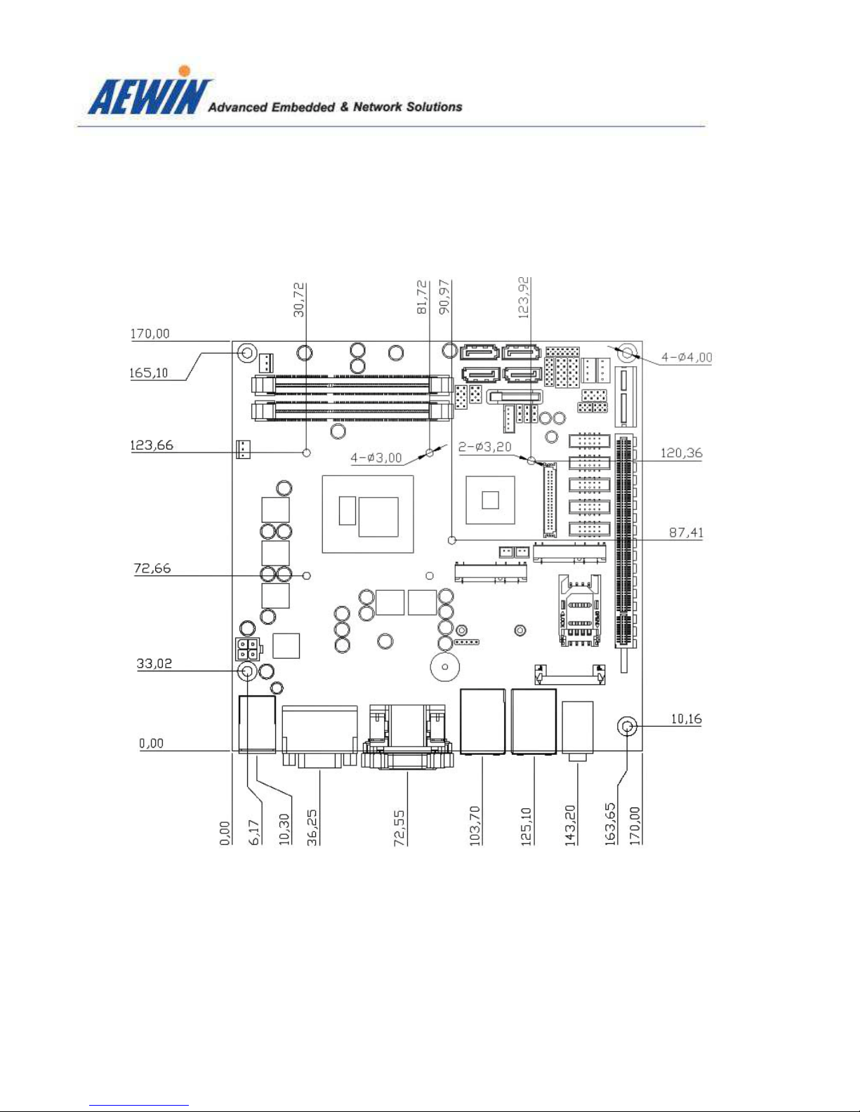
12
1.4 Board Layo t Dimension
AEWIN Technologies Co., Ltd MB-8300 User Man al
13
AEWIN Technologies Co., Ltd MB-8300 User Man al
14
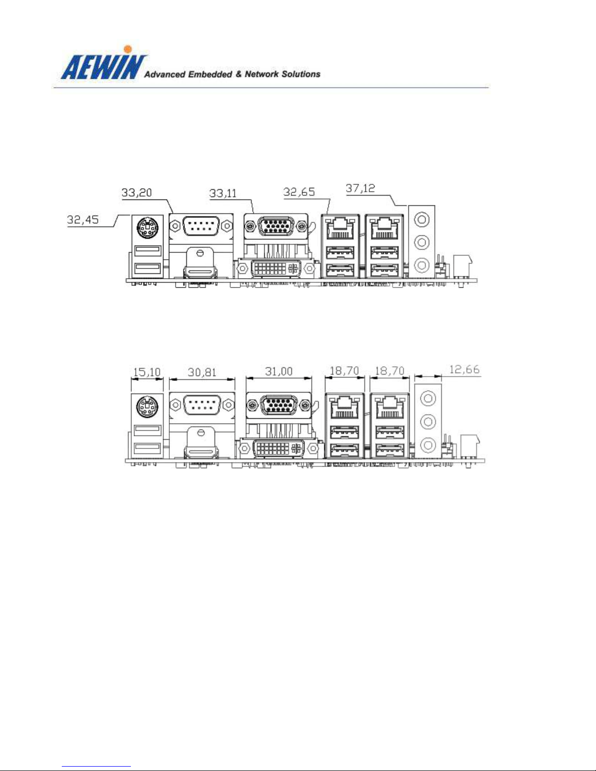
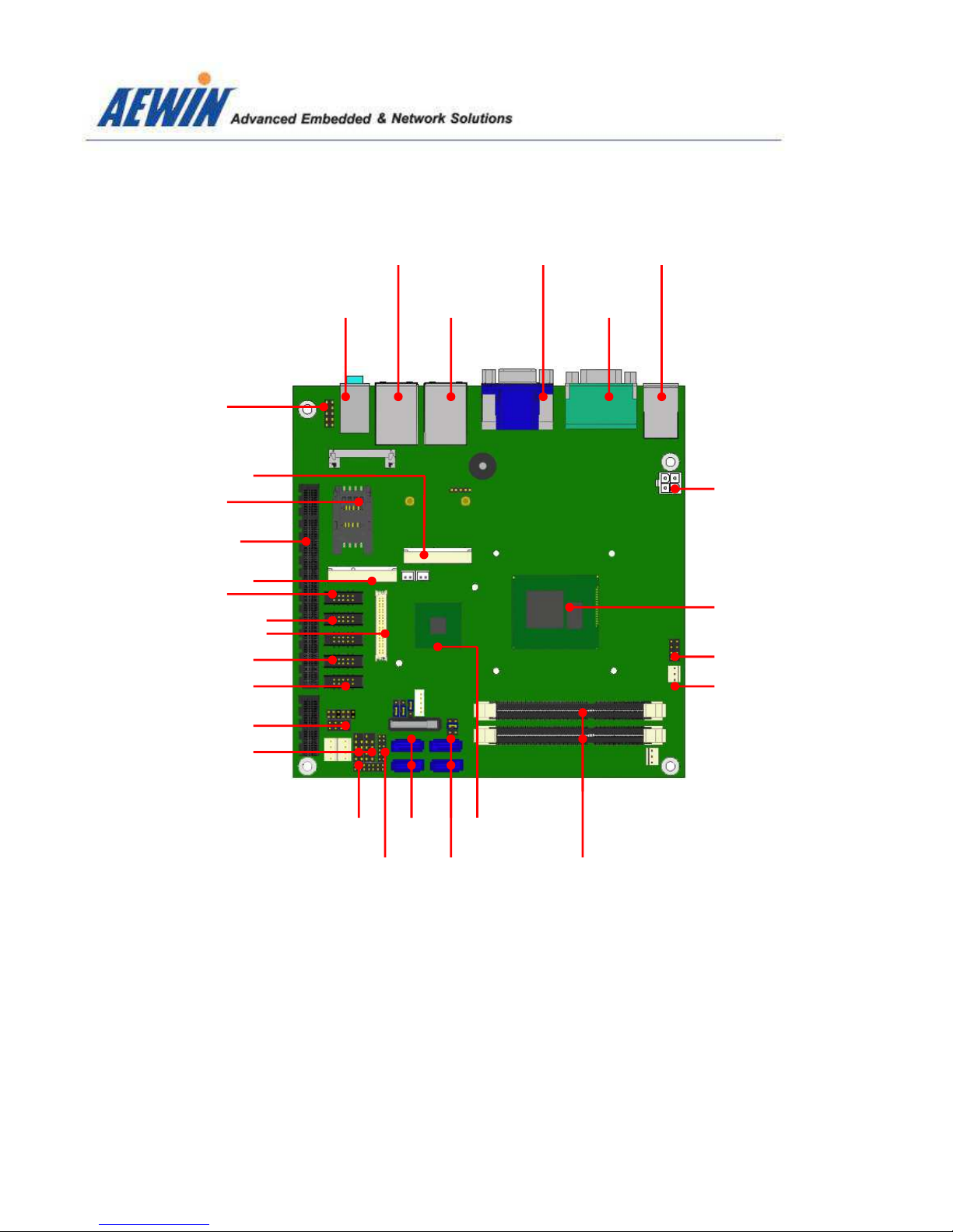
1.5 IO ports
Intel® Core i7/i5/i3
Processor
Intel® QM87
SATA3LPC
DDR3 SO-DIMMSATA3
Audio
GLAN + USB3.0
GLAN + USB3.0
VGA + DVI-D
COM + HDMI
PS2 Key/Mouse + USB2.0
DC 8V ~ 32V In
CPU Fan connector
Half-size Mini-PCIe
SIM card holder
PCI-Express X16
Full-size Mini-PCIe
RS232/422/485
24-bit Dual-CH LVDS
RS232
RS232
Dual USB2.0
GPIO
RS232
SPI Flash
Front audio
Front Panel

AEWIN Technologies Co., Ltd MB-8300 User Man al
15
PS2 Key/Mo se RS232 VGA
GLAN GLAN A dio
D al USB2.0 HDMI DVI-D D al USB3.0 D al USB3.0 PCIe X16 slot

AEWIN Technologies Co., Ltd MB-8300 User Man al
16
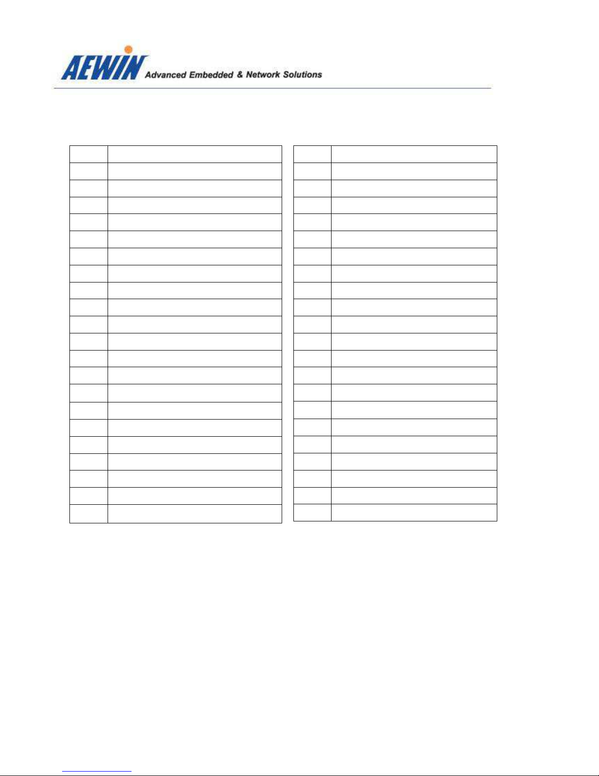
2.1 The location of onboard connectors
CN37 CN33 CN34 CN35 CN31
CN4
CN5
CN32 CN30 CN29
CN27
Sys Fan
C U Fan
CN26
CN25
CN22
CN20
CN16
CN18
CN15
CN13
CN19
CN17
CN14
CN8
CN1
CN7
CN6
CN10
CN3
CN9
CN11
CN12
CN23
CN24
CN28
CN2
CN38
AEWIN Technologies Co., Ltd MB-8300 User Man al
17
Label Function
CN1 Low Pin Count
CN2 SATA3
CN3 SATA3
CN4 SATA power
CN5 SATA power
CN6 GPIO
CN7 USB 2.0 Pin header
CN8 USB 2.0 Pin header
CN9 SATA3
CN10 SATA3
CN11 SPI Programmer
CN12 PCI-Express X1 slot
CN13 Power on/off, Reset, HDD/Power LED
CN14 LVDS backlight inverter
CN15 COM4
CN16 COM3
CN17 COM5
CN18 24-bit LVDS
CN19 COM6
CN20 COM2
CN21 PCI-Express X16 slot
Label Function
CN22 Half-size Mini-PCIe LED
CN23 Full-size Mini-PCIe LED
CN24 Full-size Mini-PCIe socket
CN25 Half-size Mini-PCIe socket
CN26 SIM card holder
CN27 SMBUS pin header
CN28 P4 4-pin power input connector
CN29 RJ45 LAN + Dual USB 3.0
CN30 RJ45 LAN + Dual USB 3.0
CN31 PS2 keyboard/mouse + Dual USB 2.0
CN32 Audio jack
CN33 VGA connector
CN34 COM1
CN35 HDMI connector
CN36 N/C
CN37 DVI-D connector
CN38 Front Audio header
CN39 N/C
CN40 N/C
CN41 N/C
CN42 N/C
AEWIN Technologies Co., Ltd MB-8300 User Man al
18
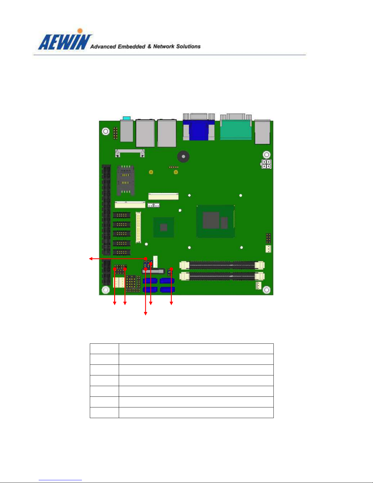
2.2 The location of onboard j mpers
Label Function
JP1 Panel Voltage ( VCC ) select
JP2 COM3 Pin-9 select mode ( RI/5V/12V )
JP3 COM4 Pin-9 select mode ( RI/5V/12V )
JP4 LVDS backlight control mode select
JP5 CMOS Clear jumper
JP6 AT/ATX power mode jumper select
J 6
J 1 J 4 J 2
J 5
J 3

AEWIN Technologies Co., Ltd MB-8300 User Man al
19
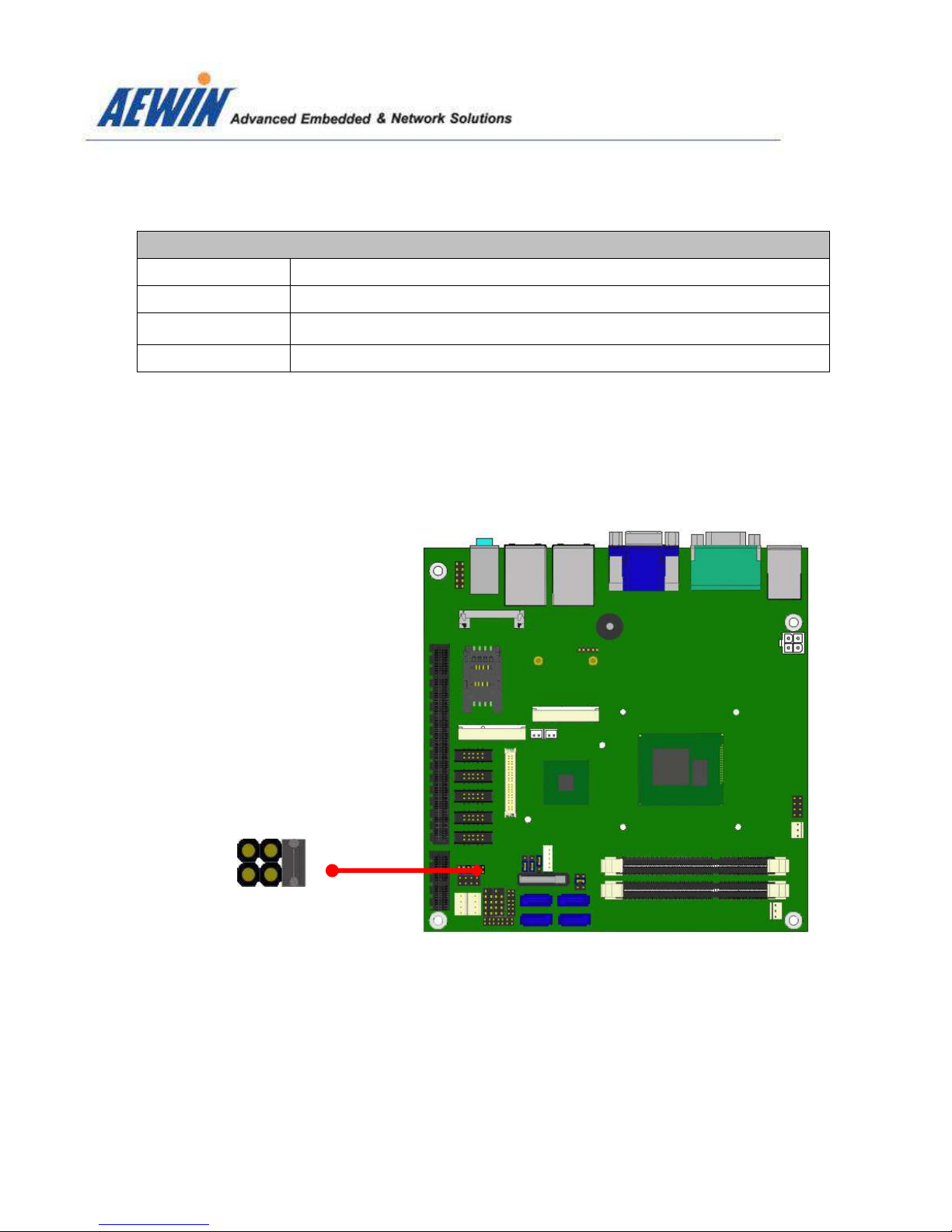
2.3 The f nction list of onboard j mpers setting
-2.3.1 : JP1 for Panel Voltage select
J 1
1 2
JP1
Closed Pin Res lt
1-2 * +3.3V
3-4 +5V
5-6 +12V
*
Defa lt setting
5 6
AEWIN Technologies Co., Ltd MB-8300 User Man al
20
-2.3.2: JP2 for COM3 box header Pin-8 f nction select
J 2
1
2
JP2
Closed Pin Res lt
1-2 * RI
3-4 +5V
5-6 +12V
*
Defa lt setting
5
6
This manual suits for next models
7
Table of contents
Other Aewin Motherboard manuals


