Aewin AW-E652 User manual

VIA C3 Low Power Processors Embedded SBC
User’s Manual
Version 1.4

i
© Copyright 2005. All Rights Reserved
Manual edition 1.4, Nov.2005
This document contains proprietary information protected by copyright. All rights
are reserved, no part of this manual may be reproduced, copied, translated or
transmitted in any form or by any means without prior written permission of the
manufacturer.
The content of this manual is intended to be accurate and reliable, the original
manufacturer assumes no responsibility for any inaccuracies that may be contained in
this manual. The original manufacturer reserves the right to make improvements to
the products described in this manual at any time without prior notice.
Trademarks
IBM, EGA, VGA, XT/AT, OS/2 and PS/2 are registered trademarks of International
Business Machine Corporation
Award is a trademark of Award Software International, Inc
RTL is a trademark of Realtek Semi-Conductor Co., Ltd
VIA is a trademark of VIA Technologies, Inc
Winbond is a trademark of Winbond Technology, Inc
CF and CompactFlash are trademark of ScanDisk Corporation
Microsoft, Windows, Windows NT and MS-DOS are either trademarks or registered
trademarks of Microsoft Corporation
All other product names mentioned herein are used for identification purpose only and
may be trademarks and/or registered trademarks of their respective companies
Limitation of Liability
While reasonable efforts have been made to ensure the accuracy of this manual, the
manufacturer and distributor assume no liability resulting from errors or omissions in
this manual, or from the use of the information contained herein.

ii
Table of Contents
Chapter 1. General Information
1.1 Introduction---------------------------------------------------------------------------------1
1.2 Specification---------------------------------------------------------------------------------1
1.3 AW-E652 Package--------------------------------------------------------------------------3
1.4 Board Layout--------------------------------------------------------------------------------4
1.5 Board Dimension---------------------------------------------------------------------------4
Chapter 2. Connectors Location and Configuration
2.1 Connectors/Jumpers Location and Define--------------------------------------------5
2.2 Onboard Processors-----------------------------------------------------------------------6
2.3 Installing System Memory----------------------------------------------------------------6
2.4 Connector and Jumpers Settings-------------------------------------------------------7
CN1: VGA D-Sub Connector------------------------------------------------------------7
CN2: COM1 D-Sub Connector---------------------------------------------------------8
CN3: PS/2 Mouse/KB Connector-------------------------------------------------------8
CN4: IR Connector------------------------------------------------------------------------9
CN5: LAN RJ-45 Connector------------------------------------------------------------9
CN6: USB Connector--------------------------------------------------------------------10
CN7: Internal Mouse/KB Pin-Header------------------------------------------------10
CN8: LVDS Connector-------------------------------------------------------------------11
CN9: COM2 Pin-Header----------------------------------------------------------------11
CN10: PCI Interface---------------------------------------------------------------------12
CN11: LPT Pin-Header------------------------------------------------------------------13
CN12: PC/104 Connector---------------------------------------------------------------14
CN13: Power Button---------------------------------------------------------------------15
CN14: GPIO Port Connector----------------------------------------------------------15
CN15: IDE Connector-------------------------------------------------------------------16
CN16: LCD Backlight Connector-----------------------------------------------------17
CN17: Floppy Connector---------------------------------------------------------------17
CN18: USB3/4 Pin-Header-------------------------------------------------------------18
CN19: ATX Power Connector---------------------------------------------------------18
CN20: AC97 Connector-----------------------------------------------------------------18
CN21: +5V/+12 Input Connector-----------------------------------------------------19
CN22: COM3/COM4 Pin-Header----------------------------------------------------19
CN23: LCD Display----------------------------------------------------------------------20
JP1: COM1 RI/Voltage Select----------------------------------------------------------21
JP2: COM2 Mode Select----------------------------------------------------------------21

iii
JP3: Clear CMOS-----------------------------------------------------------------------22
JP4: Watchdog Output Select--------------------------------------------------------22
JP5: COM2 RI/Voltage Select--------------------------------------------------------22
JP6: COM4 RI/Voltage Select--------------------------------------------------------23
JP7: COM3 RI/Voltage Select--------------------------------------------------------23
JP8: LCD Voltage Select---------------------------------------------------------------24
JP9: COM2 RS485 Wire Select---------------------------------------------------24
Chapter 3. BIOS Setup-----------------------------------------------------------------------25
3.1 Quick Setup--------------------------------------------------------------------------------25
3.2 Entering the CMOS Setup Program--------------------------------------------------26
3.3 Menu Options------------------------------------------------------------------------------27
Standard CMOS Features--------------------------------------------------------------29
Advanced BIOS Features---------------------------------------------------------------31
Advanced Chipset Features-------------------------------------------------------------34
Integrated Peripherals-------------------------------------------------------------------37
Power Management Setup--------------------------------------------------------------41
PNP/PCI Configuration-----------------------------------------------------------------43
PC Health Status--------------------------------------------------------------------------44
Frequency/Voltage Control-------------------------------------------------------------45
Load Fail-Safe Default-------------------------------------------------------------------45
Load Optimized Default-----------------------------------------------------------------46
Set Supervisor & User Password------------------------------------------------------46
Save & Exit Setup-------------------------------------------------------------------------47
Save Without Saving---------------------------------------------------------------------48
Chapter 4. Drivers and Utilities Installation---------------------------------------------49
System Driver Installation------------------------------------------------------------------49
Audio Driver Installation--------------------------------------------------------------------54
VGA Driver Installation---------------------------------------------------------------------56
Ethernet Driver Installation ----------------------------------------------------------------58
Appendix A. Programming the Watchdog Timer--------------------------------------65
Appendix B. Audio Kit-----------------------------------------------------------------------66
Appendix C. Installing PC/104 Module--------------------------------------------------69
Appendix D. Programming the GPIO Port----------------------------------------------69
Appendix E. Interrupt Controller---------------------------------------------------------70
Appendix F. Optional Cable List----------------------------------------------------------73

iv

User’s manual
AW-E652
1
Chapter 1. General Information
1.1 Introduction
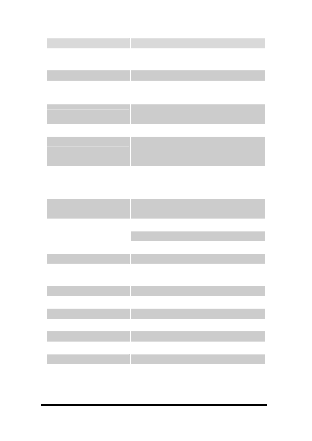
The AW-E652 is a full function of 3.5” Embedded format SBC board use VIA
VT8606 and VT82C686B chipset supports processors VIA Ezra/Eden (EBGA
packaging) processors. The AW-E652 supports CRT and 36-bit TFT panels, Realtek
RTL8139C+ Ethernet chipset with RJ45 jack for 10/100Mbps and AC-97 Audio
Interface.
The onboard features include three RS-232 and one RS-232/422/485 serial ports, one
bi-directional parallel port and onboard SSD interface supports 50-pin CompactFlash
socket for TypeI/II CompactFlash Card. The AW-E652 supports up to 4 USB
included two USB ports and pin-header for USB3/4, 8 Digital Input/8 Output as well
as the Watchdog timer. For the expansion ability, the AW-E652 reserved a PC/104
connector and proprietary PCI connector onboard.
1.2 Specification
CPU VIA Ezra/Eden (EBGA package) processor
BIOS Award® 256KB Flash BIOS
Chipset VIAVT8606 + VT82C686B
I/O Chipset Built-in VT82C686B + Winbond 83977EF
Memory One 144-pin SO-DIMM socket support up to
512Mbytes SDRAM
Enhanced IDE Support up to two IDE devices (Ultra DMA
33/66/100).
FDD interface Support 34-pin header up to two floppy disk drives
Parallel port One bi-directional parallel port. Support
SPP/ECP/EPP
Serial port Three RS-232 and one RS-232/422/485 serial ports.
IR interface Support one IrDATx/Rx header
KB/Mouse connector Support PC/AT keyboard and PS/2 mouse
USB connectors Support four USB ports
Battery Lithium battery for data retention up to 10 years(in
normal condition)
Watchdog Timer Can generate a system reset, or IRQ11. Support
software selectable timeout interval.
User’s manual
AW-E652
2
Digital I/O Eight digital output and eight input
PCI Connector Optional proprietary PCI connector for PCI
expansion
PC/104 Connector One PC/104 connector
Power management APM 1.1 compliant
Flat Panel/CRT Interface
Chipset VIATwister chip with integrated Savage4
2D/3D/Video Accelerator
Display memory Share system memory 8/16/32MB
Interface
4x AGPVGA/LCD interface, support for 9, 12, 15,
18, 24, 36 bit TFT and optional 16 or 24-bit DSTN
Panel
Display type Support CRT, 36bit TTLTFT LCD and LVDS
interface
Ethernet Interface
Chipset Realtek RTL8139C+ 100Base-TX Fast Ethernet
controller
Ethernet interface PCI 100/10 Mbps Ethernet controller
SSD Interface One 50-pin CompactFlash™ socket
Sound Interface (Optional via Audio Kit)
Chipset Option AC 97 codec
Audio controller SoundBlaster Pro Hardware and Direct Sound
Ready AC97 Digital Audio
Audio interface Mic in,, Line in, Speaker out and CD audio in
Mechanical and Environmental
Power supply voltage VCC (4.75V to 5.25V)
Max. power requirements 4A @ 5 V, 200mA/+12V
Operating temperature 32 to 140°F (0 to 60°C)
Board size 5.7"(L) x 4"(W) (145mm x 102mm)
Weight 0.26 lb. (0.57 Kg) (bare)
1.3 AW-E652 Package
Please make sure that the following items have been included in the
package before installation.
1. AW-E652 VIA C3 Single Board

User’s manual
AW-E652
3
2. Quick Setup
3. Cable: Please refer to Appendix F Optional Cables
4. CD-ROM which contains the following folders:
(1) Manual
(2) LAN Driver
(3) Tools
(4) Chipset Driver
(5) VGA Driver
(6) Sound Driver
If any of these items are missing or damaged, please contact your dealer
from whom you purchased the board at once. Save the shipping
materials and carton in the event that you want to ship or store the board
in the future. After you unpack the board, inspect it to assure an intact
shipment. Do not apply power to the board if it appears to have been
damaged.
Leave the board in its original packing until you are ready to install
Precautions
Please make sure you properly ground yourself before handling the AW-E652 board
or other system components. Electrostatic discharge can be easily damage the
AW-E652 board.
Do not remove the anti-static packing until you are ready to install the AW-E652
board.
Ground yourself before removing any system component from it protective anti-static
packaging. To ground yourself, grasp the expansion slot covers or other unpainted
parts of the computer chassis.
Handle the AW-E652 board by its edges and avoid touching its component.
1.4 Board Layout
User’s manual
AW-E652
4
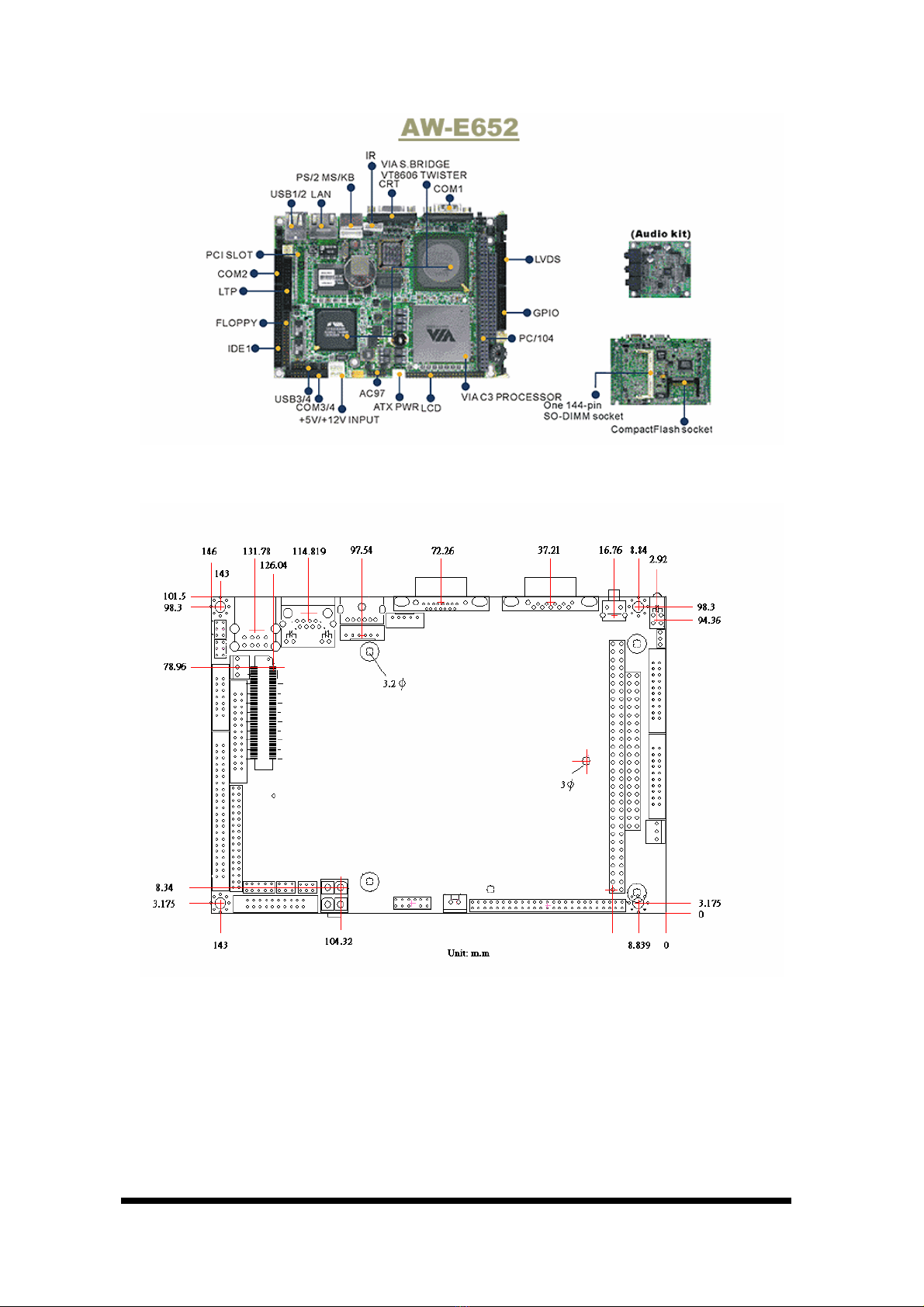
1.5 Board Dimension
Chapter 2. Connectors/Jumpers Location and Configuration
User’s manual
AW-E652
5
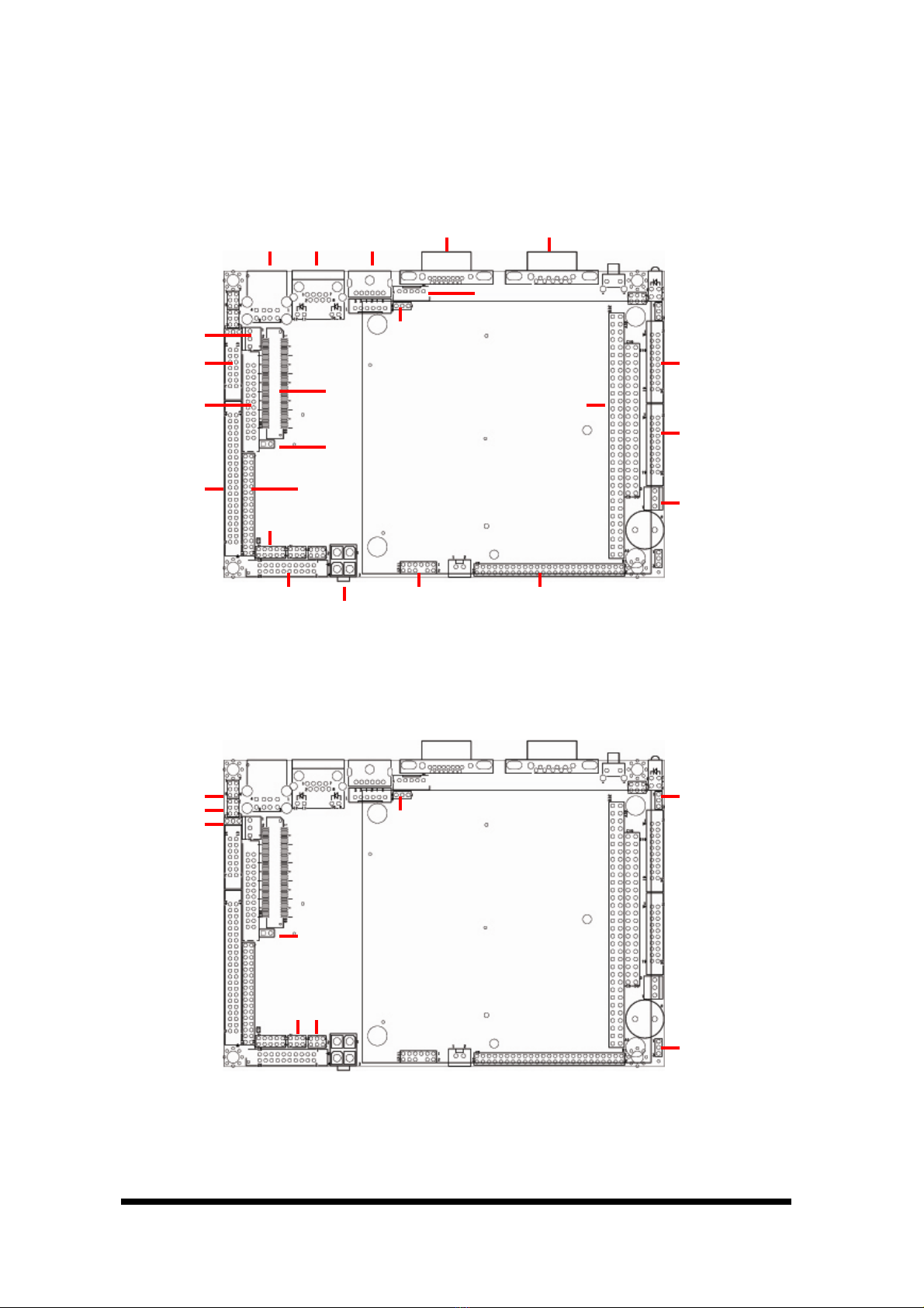
2.1 Connectors/Jumpers Location and Define
CN1 CN2CN3CN5CN6
CN7
CN23CN20CN22 CN21
CN18
CN19
CN9
CN15
CN11
CN12
CN8
CN14
CN16
CN4
CN10
CN13
CN17
JP2
JP5
JP9
JP1
JP4
JP8
JP3
JP6 JP7

User’s manual
AW-E652
6
Connector Description Connector Description
CN1 VGA Connector (D-Sub) CN13 Power Button
CN2 COM1 Connector (D-Sub) CN14 GPIO Port Connector
CN3 PS/2 KB/MS Connector (D-Sub) CN15 IDE Connector
CN4 IR Connector CN16 LCD Backlight Enable Connector
CN5 LAN Connector (RJ45) CN17 Floppy Connector
CN6 USB Connector CN18 USB3/4 Connector (Pin Header)
CN7 Internal KB/MS Connector(Hader) CN19 ATX Power Connector
CN8 LVDS Connector CN20 AC97 Connector
CN9 COM2 Connector(RS232/422/485) CN21 +5V/+12V Input Connector
CN10 PCI Interface CN22 COM3/COM4 Connector (Header)
CN11 LPT1 Connector (Pin Header) CN23 LCD Display Connector
CN12 PC/104 Connector
Pin Define Pin Define
JP1 COM1 RI/Voltage Select JP5 COM2 RI/Voltage Select
JP2 COM2 Mode Select JP6 COM4 RI/Voltage Select
JP3 Clear CMOS JP7 COM3 RI/Voltage Select
JP4 Watchdog Output Select JP8 LCD Voltage Select
JP9 COM2 RS485 Wire Select
2.2. Onboard Processors
The AW-E652 has onboard built-in VIAEzra or EDEN EBGA Package processor.
The CPU cooler fan will be mounted when board with 800MHz or 667MHz CPU and
the high profile Heatsink will be mounted when 667MHz CPU.
2.3 Installing Memory
To insert a SO-DIMM Memory:
The AW-E652 supports one 144-pin SO-DIMM sockets, memory up to 512Mbyte.
To Insert a SO-DIMM Memory: Please align the module with the socket key and
press down until the levers at each end of the socket snap close up.
There is only one direction for installing a module in the socket. Do not attempt to
force the module into the socket incorrectly.
To Remove a SO-DIMM Memory: To remove a SO-DIMM, press down on the
levers at both end of the module until the module pops out
There is only one direction for installing a module in the socket. Do not attempt to
force the module into the socket incorrectly.

User’s manual
AW-E652
7
2.4 Connector and Jumper Settings
CN1: VGA Connector
Pin Define
1 Red
2 Green
3 Blue
4 MONID0
5 Ground
6 Ground
7 Ground
8 Ground
9 +5V
10 Ground
11 MONID1
12 DDC Data
13 H-Sync
14 V-Sync
15 DDC Clock
User’s manual
AW-E652
8
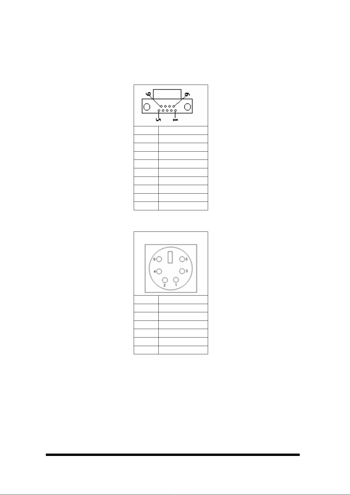
CN2: COM1 Connector (D-Sub)
Pin Define
1 DCD
2 RXD
3 TXD
4 DTR
5 Ground
6 DSR
7 RTS
8 CTS
9 RI
CN3: PS/2 Mouse/Keyboard Connector (MINI DIN Jack)
Pin Define
1 KBDATA
2 MSDATA
3 Ground
4 +5V
5 KBCLK
6 MSCLK
User’s manual
AW-E652
9
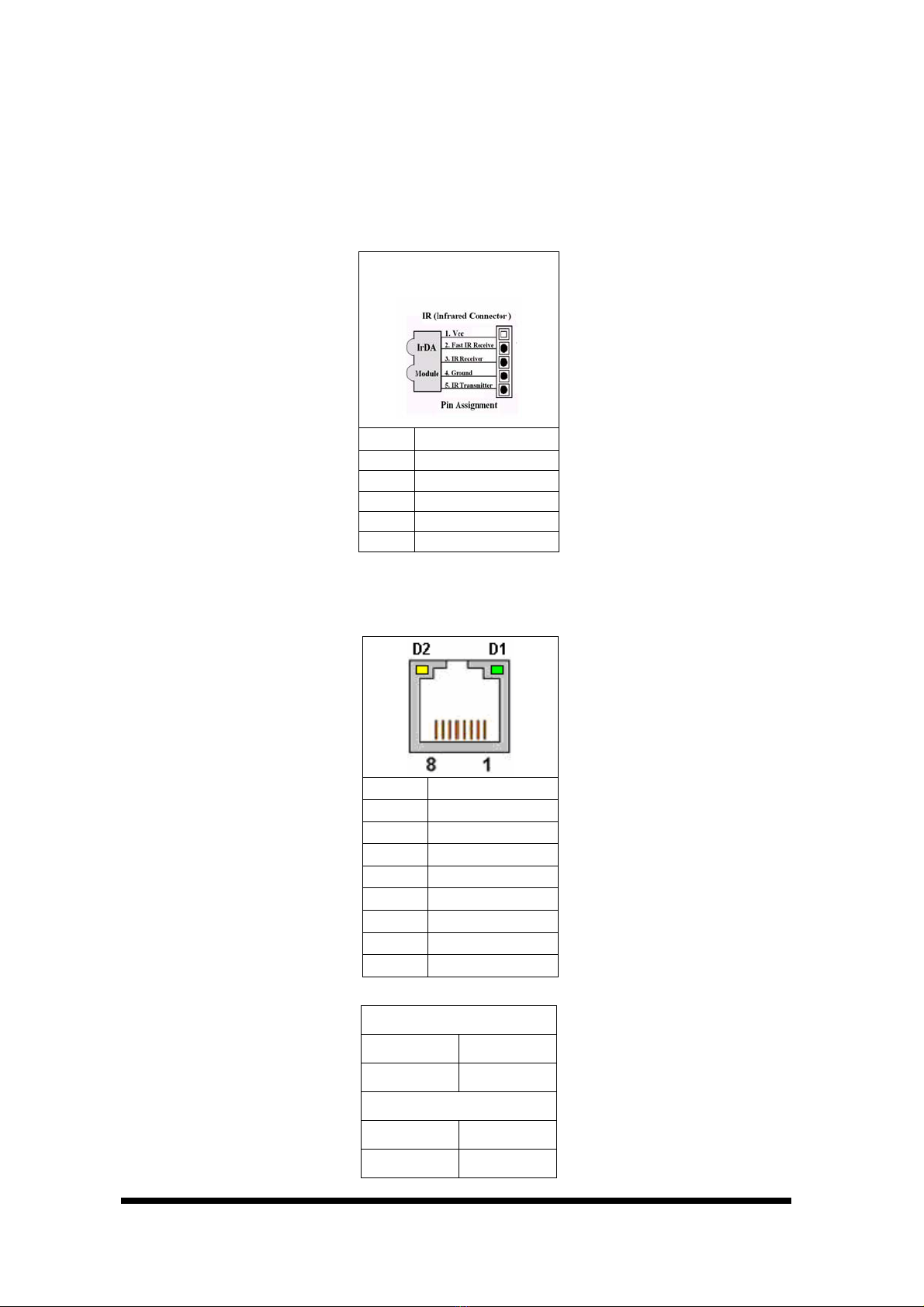
CN4: IR Connector
The onboard IR connector with a 2.0mm pitch pin header
Pin Define
1 +5V
2 Fast IR Receive
3 IR Receiver
4 Ground
5 IR Transmitter
CN5: LAN Connector (JR-45)
Pin Define
1 TX0+
2 TX0-
3 RX0+
4 NC
5 NC
6 RX0-
7 NC
8 NC
LED:
D1: Speed indicated LED
10 Mbps DIM
100 Mbps GREEN
D2 :Link/Activity LED
Link YELLOW
Activity BLINKING

User’s manual
AW-E652
10
CN6: USB Connector
Pin Define
1 5VUSB0
2 USBDT0-
3 USBDT0+
4 Ground
5 5VUSB0
6 USBDT1-
7 USBDT1+
8 Ground
CN7: Internal KB/MS Connec tor
The AW-E652 supports an internal keyboard/mouse with 2mm pitch pin header for
flexible using.
Pin Define
1 KB-CLK
2 KB-DATA
3 MS-CLK
4 Ground
5 KBMSVCC
6 MSDAA

User’s manual
AW-E652
11
CN8: LVDS Connector
The AW-E652 supports LVDS by using a 20-pin of connector for LVDS Panel
Pin Define Pin Define
1 Y0P 2 Y1P
3 Y0M 4 Y1M
5 Ground 6 Ground
7 Y2P 8 NC
9 Y2M 10 NC
11 Ground 12 Ground
13 YCP 14 VCCLCD
15 YCM 16 VCC LCD
17 Ground 18 NC
19 V12P0 20 V12P0
CN9: COM2 Connector
The AW-E652 supports four serial ports, onboard COM2 with a 2.00mm pitch pin
header.
Pin Define
1 DCD2#N
2 DSR2#N
3 RXD2 IN
4 RTS#2OUT
5 TXD2OUT
6 CTS2#N
7 DTR#2OUT
8 RI#2_5V_12V
9 Ground
10 NC
11 485TXD+/422TXD+
12 485TXD-/422TXD-
13 422RXD+
14 422RXD-
User’s manual
AW-E652
12
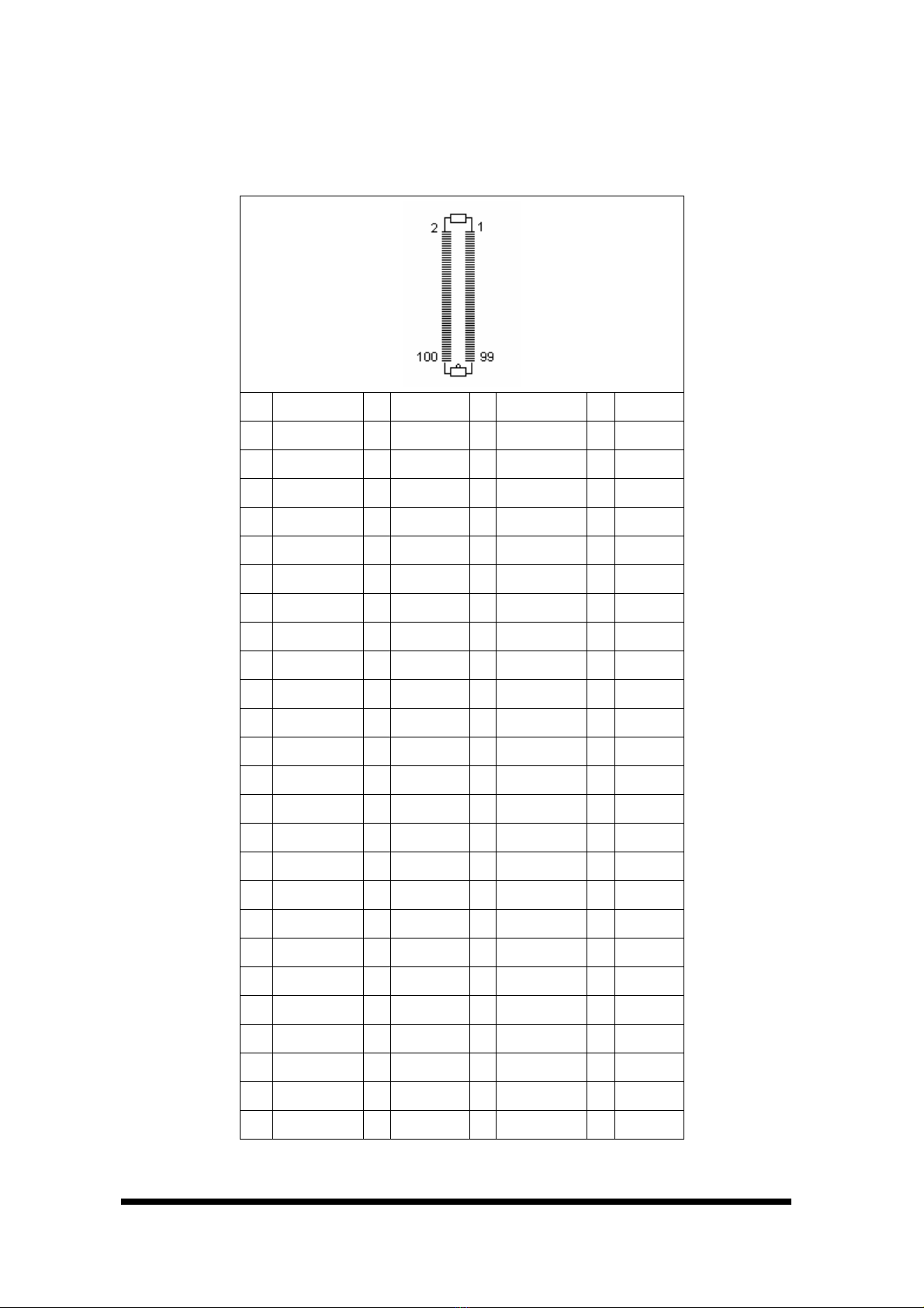
CN10: PCI Interface
The AW-E652 supports one micro PCI slot for expansion.
Pin Signal Pin Signal Pin Signal Pin Signal
1 GND 26 PCICLK1 51 +3.3V 76 SERR-
2 GND 27 PCIRST- 52 +3.3V 77 AD15
3 +12V 28 GND 53 AD22 78 C/BE1-
4 +12V 29 GNT4- 54 AD21 79 AD13
5 GND 30 +5V 55 AD20 80 AD14
6 +5V 31 REQ2- 56 AD19 81 GND
7 +5V 32 +5V 57 AD18 82 GND
8 +5V 33 +5V 58 AD19 83 AD11
9 +5V 34 REQ4- 59 AD16 84 AD12
10 INTB- 35 +5V 60 C/BE2- 85 AD9
11 INTA- 36 AD31 61 GND 86 AD10
12 INTD- 37 AD30 62 GND 87 C/BE0-
13 INTC- 38 AD29 63 FRAME- 88 AD8
14 REQ3- 39 AD28 64 IRDY- 89 AD6
15 GND 40 +3.3V 65 GND 90 AD7
16 REQ1- 41 GND 66 GND 91 +5V
17 PCICLK2 42 GND 67 TRDY- 92 +5V
18 GNT3- 43 AD26 68 DEVSEL- 93 AD4
19 GND 44 AD27 69 GND 94 AD5
20 GND 45 AD24 70 PLOCK- 95 AD2
21 PCICLK3 46 AD25 71 GND 96 AD3
22 PCICLK0 47 GNT2- 72 GND 97 AD0
23 GND 48 C/BE3- 73 +3.3V 98 AD1
24 GND 49 +3.3V 74 PERR- 99 GND
25 GNT1- 50 AD23 75 PAR 100 GND
User’s manual
AW-E652
13
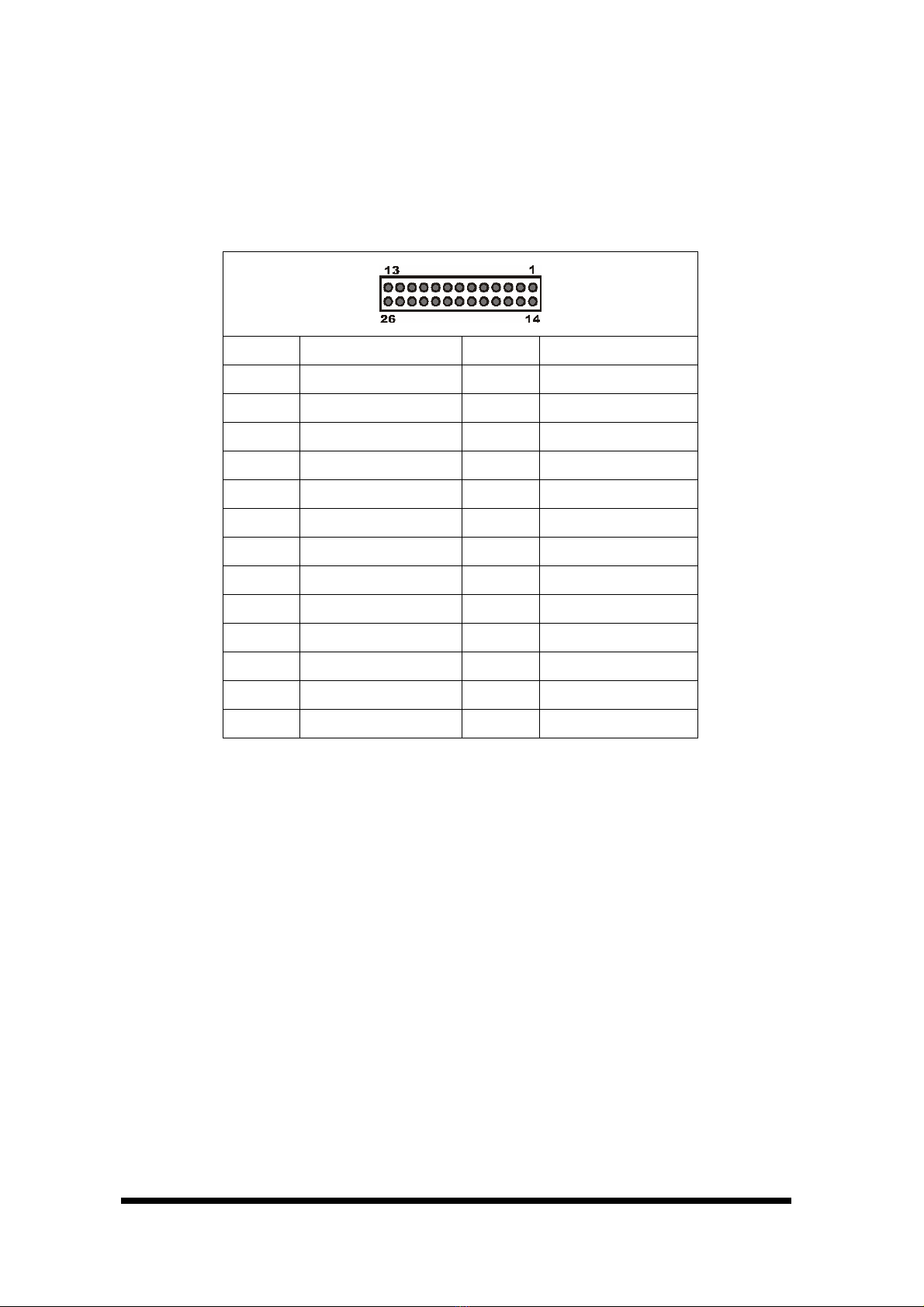
CN11: LPT Connector
The AW-E652 supports a 26-pin pin header LPT connector by using 2mm pitch
connector.
Pin Define Pin Define
1 PT_STB# 14 PTAFD#
2 PT_D0 15 PTERROR#
3 PT_D1 16 PTINT#
4 PT_D2 17 PTSLIN#
5 PT_D3 18 Ground
6 PT_D4 19 Ground
7 PT_D5 20 Ground
8 PT_D6 21 Ground
9 PT_D7 22 Ground
10 PTACK# 23 Ground
11 PTBUSY 24 Ground
12 PTPE 25 Ground
13 PTSLCT 26 Ground

User’s manual
AW-E652
14
CN12: PC/104 Connector
CN12 is a standard PC/104 bus connector, and it is fully occupied with the signals of
the “ISA” (PC/AT) bus. It offers full architecture, hardware and software
compatibility with the ISA bus and can accept ultra-compact (3.6” x 3.8”) stackable
modules.
Signal Pin Signal Pin Signal Pin Signal Pin
Ground C0 Ground D0 IOCHCHK A1 Ground B1
SBHE* C1 MEMCS16* D1 SD7 A2 RESET B2
LA23 C2 IOSC16* D2 SD6 A3 +5V B3
LA22 C3 IRQ10 D3 SD5 A4 IRQ9 B4
LA21 C4 IRQ11 D4 SD4 A5 NC B5
LA20 C5 IRQ12 D5 SD3 A6 NC B6
LA19 C6 IRQ15 D6 SD2 A7 NC B7
LA18 C7 IRQ14 D7 SD1 A8 0 wait state B8
LA17 C8 DACL0* D8 SD0 A9 +12V B9
MEMR* C9 DRQ0* D9 IOCHRDY A10 Ground B10
MEMW* C10 DACK5* D10 AEN A11 SMEMW# B11
SD8 C11 DRQ5 D11 SA19 A12 SMEMR* B12
SD9 C12 DACK6* D12 SA18 A13 IOW* B13
SD10 C13 DRQ6 D13 SA17 A14 IOR* B14
SD11 C14 DACK7* D14 SA16 A15 DACK3* B15
SD12 C15 DRQ7 D15 SA15 A16 DRQ3 B16
SD13 C16 +5V D16 SA14 A17 DACK1* B17
SD14 C17 MASTER* D17 SA13 A18 DRQ1 B18
SD15 C18 Ground D18 SA12 A19 REFRESH* B19
Ground C19 Ground D19 SA11 A20 SYSCLK B20
SA10 A21 IRQ7 B21
SA9 A22 IRQ6 B22
SA8 A23 IRQ5 B23
SA7 A24 IRQ4 B24
SA6 A25 IRQ3 B25
SA5 A26 NC B26
SA4 A27 TC B27
SA3 A28 BALE B28
SA2 A29 +5V B29
SA1 A30 OSC B30
SA0 A31 Ground B31
Ground A32 Ground B32
Please see how to install the PC/104 module in Appendix C.
User’s manual
AW-E652
15
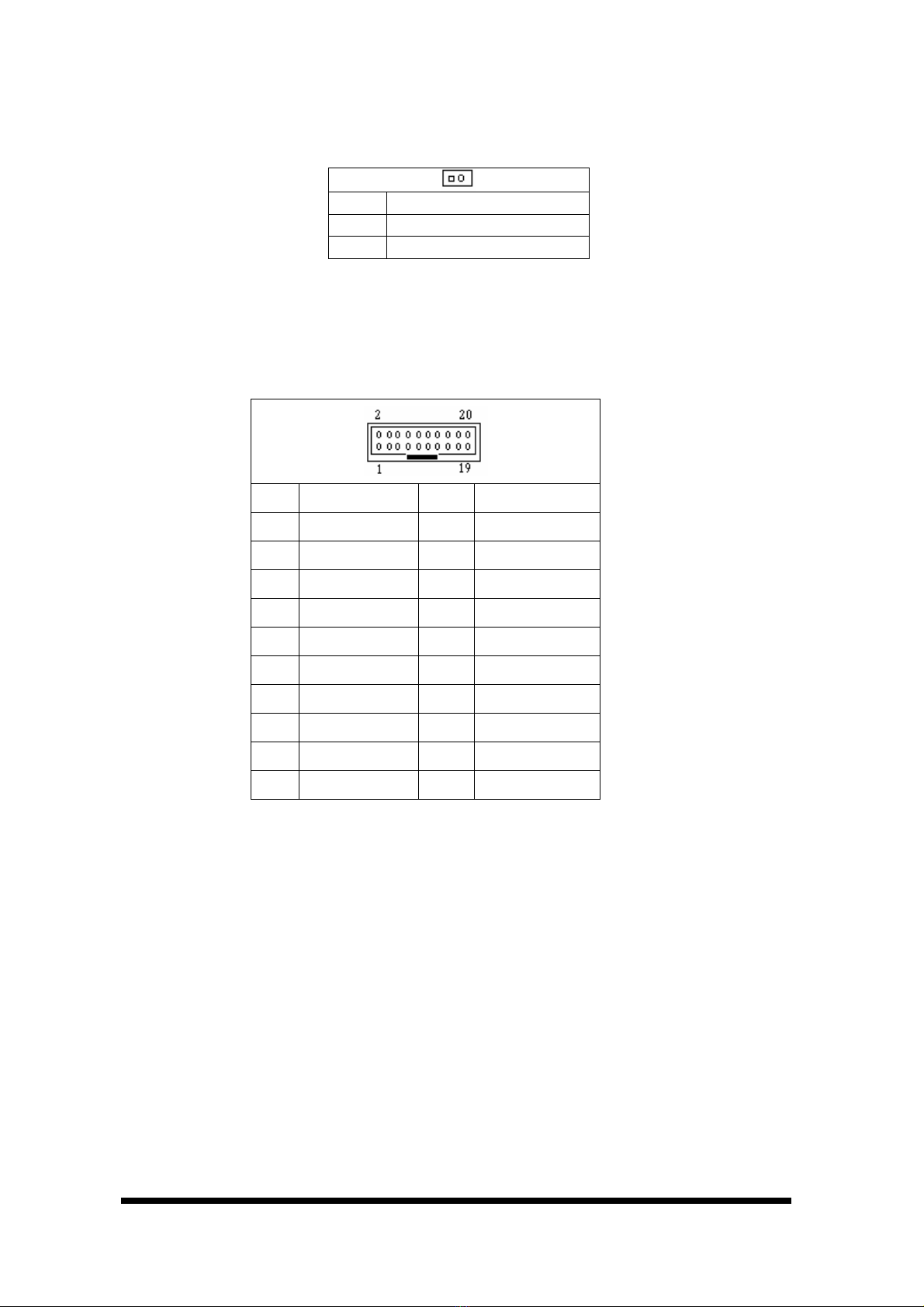
CN13: Power Button
Pin Define
1 PWBTN#
2 Ground
CN14: GPIO Port Connector
The onboard supports eight digital input and eight output which using a 2.0mm pitch
connector
Pin Define Pin Define
1 V5P0 2 V3P3
3 GPIN0 4 GPIN1
5 GPIN2 6 GPIN3
7 GPIN4 8 GPIN5
9 GPIN6 10 GPIN7
11 Ground 12 Ground
13 GPOUT0 14 GPOUT1
15 GPOUT2 16 GPOUT3
17 GPOUT4 18 GPOUT5
19 GPOUT6 20 GPOUT7
Table of contents
Other Aewin Motherboard manuals


