Afag PEZ-52 Technical specifications

Gantry axis
PEZ-52 / PEZ-65
PEZ-80 / PEZ-100
-Declaration of Incorporation
-Module Information
-Montage Instructions
-Maintenance Instructions
„Translation“ of the Original Montage Instructions
© Copyright by Afag Automation AG

Seite 2 PEZ-52-65-80-100 BA-vers.1.3 gb.15.10.14.doc
These Montage Instructions apply to:
Gantry axis
PEZ-52
Gantry axis
PEZ-65
PEZ-80
PEZ-100
Version of this documentation:PEZ Gantry axis
PEZ-52-65-80-100 BA-vers.1.3 gb.15.10.14
Symbols: Assembly and initial start-up must be carried out by qualified personnel
only and according to these Montage Instructions.
DANGER
Indicates an immediate threatening danger.
Non-compliance with this information can result in death or
serious personal injuries (invalidity).
WARNING
Indicates a possible dangerous situation.
Non-compliance with this information can result in death or
serious personal injuries (invalidity).
CAUTION
Indicates a possibly dangerous situation.
Non-compliance with this information can result in damage to
property or light to medium personal injuries.
NOTE
Indicates general notes, useful operator tips and operating
recommendations which don't affect safety and health of the
personnel.

PEZ-52-65-80-100 BA-vers.1.3 gb.15.10.14.doc Seite 3
Table of contents:
1.0.0 Declaration of Incorporation Page 5
1.1.0 Declaration of Incorporation according to the Machinery Directive
2006/42/EG Page 5
2.0.0 Module Information Page 6
2.1.0 Transport and storage (packing and unpacking) Page 6
2.1.1 Overview for gantry axis PEZ Page 7
2.1.2 Overview for Motor- and gear Page 8
2.1.3 Connection for gantry axis Page 9
2.1.4 Assembly possibility in annex slide Page 10
2.1.5 Centering bushings and assembly raster Page 10
2.1.6 Tightening torques for screw Page 11
2.1.7 Safety Instructions Page 11
2.1.8 Redesign for the gear annex side Page 12
2.1.9 Go forward with gear redesign and motor Page 13
2.2.0 Mounting third-party-gears Page 15
2.2.1 Preferred combinations PEZ-52 Page 16
2.2.2 Preferred combinations PEZ-65 Page 17
2.2.3 Preferred combinations PEZ-80 Page 18
2.2.4 Preferred combinations PEZ-100 Page 19
2.2.5 Installation gantry axis in system Page 20
2.2.6 Tip for annex module Page 20
2.2.7 Motor connection Page 21
2.2.8 Programming of the gantry axis Page 22
2.2.9 False service of the arrangement Page 23
2.3.0 Noise Emissions Page 24
2.3.1 SE-Power Control and technical data Page 25
3.0.0 Montage Instructions Page 26
3.1.0 These montage Instructions are valid for PEZ Page 26
3.1.1 General description Page 27
3.1.2 Safety information Page 27
3.1.3 Included in the delivery Page 28
3.1.4 Warranty Page 29

Seite 4 PEZ-52-65-80-100 BA-vers.1.3 gb.15.10.14.doc
3.1.5 Areas of application Page 29
3.1.6 Module description and construction Page 30
3.1.7 Module construction Page 31
3.1.8 Dimensions PEZ-52 Page 33
3.1.9 Technical data PEZ-52 Page 34
3.2.0 Slide unit load factors PEZ-52 Page 35
3.2.1 Dimensions PEZ-65 Page 36
3.2.2 Technical data PEZ-65 Page 37
3.2.3 Slide unit load factors PEZ-65 Page 38
3.2.4 Dimensions PEZ-80 Page 39
3.2.5 Technical data PEZ-80 Page 40
3.2.6 Slide unit load factors PEZ-80 Page 41
3.2.7 Dimensions PEZ-100 Page 42
3.2.8 Technical data PEZ-100 Page 43
3.2.9 Slide unit load factors PEZ-100 Page 44
3.3.0 Commissioning of the gantry axis Page 45
3.3.1 Programming gantry axis Page 46
3.3.2 Hot surface in the motor Page 46
4.0.0 Maintenance Instructions Page 47
4.1.0 Maintenance and servicing the gantry axis Page 47
4.1.1 Further maintenance Page 48
4.1.2 Lubrication of the linear guidance Page 48
4.1.3 Toothed belt spare parts Page 49
4.1.4 Toothed belt tension Page 51
4.1.5 Faults during operation Page 52
4.1.6 Dismantling and repair for the gantry axis Page 54
4.1.7 Accessories for the gantry axis Page 55
4.1.8 Gantry axis superstructure Page 56
4.1.9 Assembly process for load transmission unit Page 57
4.2.0 Gantry axis with double slide are special versions Page 57
4.2.1 Stroke limitation PEZ / PDZ axis Page 58
4.2.2 Cover sensor nut Page 59
5.0.0 Disposal Page 59

PEZ-52-65-80-100 BA-vers.1.3 gb.15.10.14.doc Seite 5
1.0.0 EC Declaration for Incorporation (Original documentation)
1.1.0 According to 2006/42/EC dated 09. June 2006, Appendix II B VI for
Incorporation of partly completed machinery.
The manufacturer: Afag Automation AG, Fiechtenstrasse 32, CH-4950 Huttwil,
Tel. +41 62 959 87 02, www.afag.com
As manufacturer of the partly completed machine we declare that:
The specified machine corresponds to the listed essential requirements of the
directive 2006/42/EG, wehere applicable the other directives and standards listed
below.
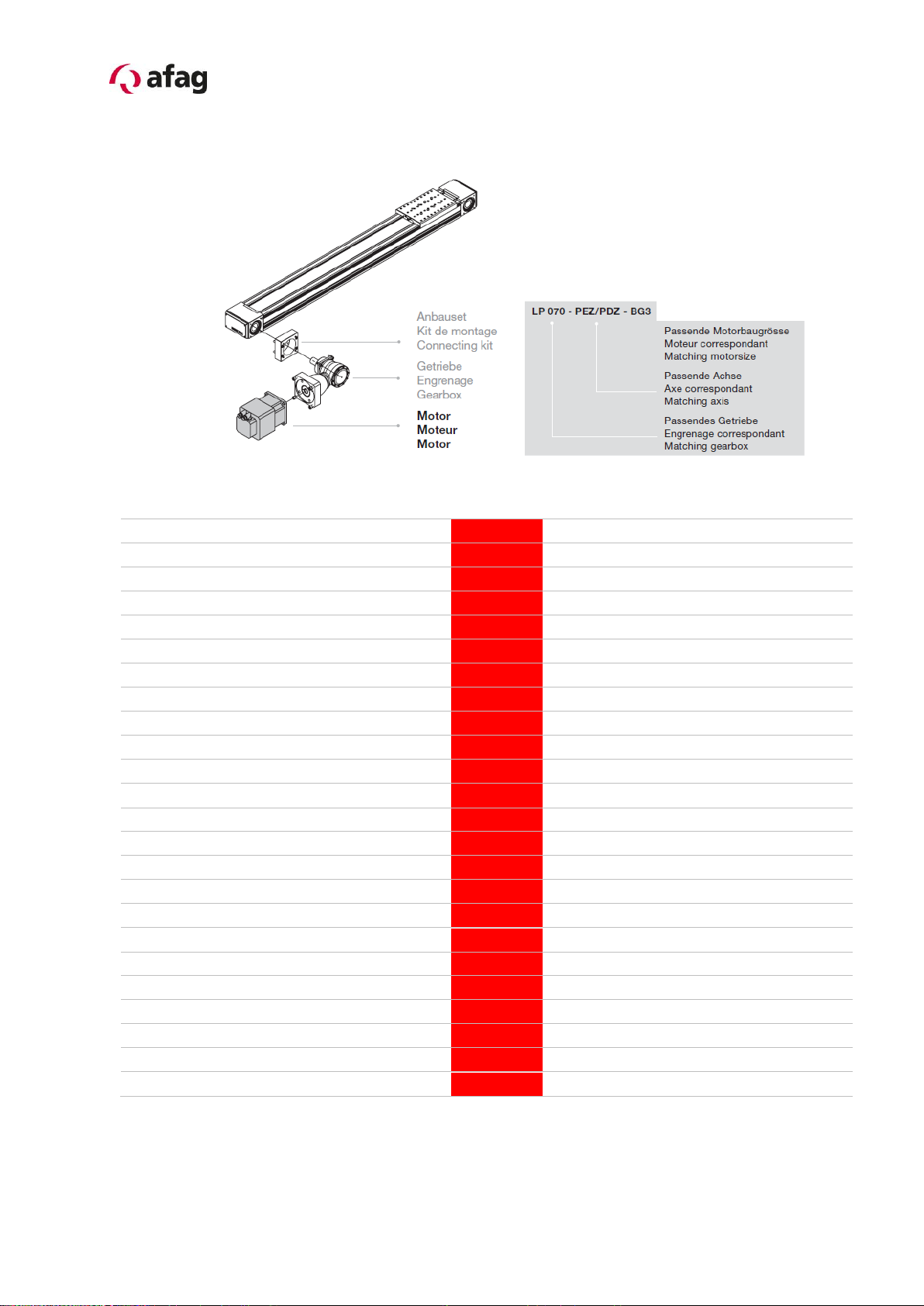
Producte name: Gantry axis PEZ (electrical)
Types: PEZ-52-65-80-100
Sequential series:
-Machinery Directive 2006/42/EC
-Low voltage Directive 2006/42/EG
-The relevant technical documentation is compiled in accordance with part B of
Annex VI
-The relevant technical documentation in accordance with part B of Annex VI
will be transmitted in response to a reasonable request by the national
authorities in printed from or in electronic from (pdf).
Increase of the harmonized
standards applied:
EN 349; EN ISO 12100-1; EN 121000-2; EN ISO
14121-1; EN 60204-1: 2006
Applied and fulfilled essential requirements:
1.1; 1.1.1; 1.1.2; 1.2; 1.2.1; 1.2.3; 1.2.4.4; 1.2.5; 1.3; 1.3.3; 1.3.5; 1.3.6; 1.3.7;
1.3.8.1; 1.3.8.2; 1.3.9; 1.4; 1.4.1; 1.5; 1.5.1; 1.6; 1.6.1; 1.6.3; 1.6.4; 1.7; 1.7.1; 1.7.4.;
1.7.4.1; 1.7.4.2; 1.7.4.3; 3.3.5; 3.4.1
This partly completed machinery must not be put into service until the final machinery
into which it is to be incorporated has been declared in conformity with the provisions
of this Directive 2006/42/EC, where appropriate.
Name and address of the person authorised to compile the relevant technical documentation:
Lanz Beat, PM & Marketing-Services, Afag Automation AG
Place/Date: Huttwil, 15.10.2014
Markus Werro
Managing Director
Afag Automation AG
Siegfried Egli
Head of HT
Afag Automation AG
Hier wird bei Auslieferung des
Geräts die aktuelle Seriennummer
eingeklebt.

Seite 6 PEZ-52-65-80-100 BA-vers.1.3 gb.15.10.14.doc
2.0.0 Module Information
2.1.0 Transport and storage (packing and unpacking)
CAUTION
Caution is required during packing and unpacking of the PEZ
gantry axis. In the case of careless handling of the gantry axis,
fingers can be crushed as the axis in the loose state can be
moved to and fro!
The module is transported in the transport packing of Afag Automation AG.
If packing of Afag Automation AG is not used, the axis must be packed in impact-
resistant and dust-proof packaging.
The axis should be stored dry in the transport packaging.
CAUTION
Caution is required to prevent back injuries during unpacking,
packing and carrying the PEZ gantry axes.
NOTE
Depending on the type of the gantry axis, the weight can be between
2.9 and 19.6 kg for the PEZ axes. We recommend binding the axes
with straps and using a hoist to lift them out of the packing crate. The
same also applies for the Installation of the gantry axes in an
assembly system.
NOTE
Please note! A technical safety information sheet is enclosed with
each module. This information sheet must be read by every person
who is involved with the module.

PEZ-52-65-80-100 BA-vers.1.3 gb.15.10.14.doc Seite 7
2.1.1 Overview for gantry module PEZ
The Motor –and Gear annex is possible in the positions A / B / C / D.
Motor
PEZ
Angular gear
Planetary gear
Mouting flange
Slide

Seite 8 PEZ-52-65-80-100 BA-vers.1.3 gb.15.10.14.doc
2.1.2 Overview for motor and gear
Bestellnummer
Typ / Type
Art. / Order
No.
PEZ-52
PEZ-65
PEZ-80
PEZ-100
Servomotor-2-320VDC-400W-45-B-R-x-x
50101765
X
X
Servomotor-2-320VDC-400W-45-x-R-x-x
50101764
X
X
Servomotor-2-48VDC-400W-45-B-R-IO-01
50101758
X
X
Servomotor-2-48VDC-400W-45-x-R-IO-01
50101757
X
X
Servomotor-2-48VDC-400W-45-B-R-IO-01
50101761
X
X
Servomotor-2-48VDC-400W-45-x-R-PB-01
50101760
X
X
Servomotor-3-320VDC-950W-45-B-R-x-x
50196417
X
X
Servomotor-3-320VDC-950W-45-x-R-x-x
50196419
X
X
Servomotor-3-560VDC-950W-45-B-R-x-x
50142523
X
X
Servomotor-3-560VDC-950W-45-x-R-x-x
50175152
X
X
Servomotor-3-48VDC-700W-30-B-R-IO-01
50217849
X
Servomotor-3-48VDC-700W-30-x-R-IO-01
50166928
X
Servomotor-3-48VDC-700W-30-B-R-PB-01
50217848
X
Servomotor-3-48VDC-700W-30-x-R-PB-01
50166927
X
Servomotor-4-560VDC-1.9kW-60-x-R-x-x
50185188
X
X
Servomotor-4-560VDC-1.9kW-60-B-R-x-x
50142524
X
X
Servomotor-4-560VDC-60-2.8kW-x-R-x-x
50245910
X
X
Servomotor-4-560VDC-60-2.8kW-B-R-x-x
50166573
X
X
Servomotor-5-560VDC-4.2kW-45-x-R-x-x
50245911
X
Servomotor-5-560VDC-4.2kW-45-B-R-x-x
50245912
X
Servomotor-5-560VDC-5.2kW-45-x-R-x-x
50245913
X
Servomotor-5-560VDC-5.2kW-45-B-R-x-x
50245914
X
Servomotor-5-560VDC-6.4kW-45-x-R-x-x
50245915
X
Servomotor-5-560VDC-6.4kW-45-B-R-x-x
50245916
X

PEZ-52-65-80-100 BA-vers.1.3 gb.15.10.14.doc Seite 9
2.1.3 Connection gantry axis.
The mounting surfaces for the gantry axes are at the bottom as standard; mounting
brackets can primarily be installed on the side grooves.
PEZ-52 PEZ-65
PEZ-80 PEZ-100
Main mounting surface:
The main mounting surface of the axes is at the bottom in the 2 grooves!
In order to avoid tensions, ensure that the bolting surface shows an evenness of at
least 0.15 mm.
NOTE
Side grooves must only be used for fixing the axes in combination
with the clamps!
main mounting surfaces

Seite 10 PEZ-52-65-80-100 BA-vers.1.3 gb.15.10.14.doc
2.1.4 Assembly possibility in annex slide
PEZ-52
PEZ-65
PEZ-80
PEZ-100
2.1.5 Centering bushings and assembly raster
PEZ
PEZ-52
Douilles de centrage
Grille / Filetage
20x20mm, M3
30x30mm, M4
38x38mm, M5
Ø5H7/1.3mm
Ø7H7/1.6mm
Ø8H7/1.8mm
PEZ
PEZ-65
PEZ-65
PEZ-80
PEZ-100
PEZ-65
PEZ-80
PEZ-100
Lochraster
30x30
48x48
38x57
38x38
(76)mm
60x60
Gewinde / Bohrung
M4
M6
M5
M5
M8
Zentrierhülsen (H7)
Ø7mm
Ø9mm
Ø9mm
Ø8mm
Ø12mm

PEZ-52-65-80-100 BA-vers.1.3 gb.15.10.14.doc Seite 11
2.1.6 Tightening torques for bolts
The bolts to be used for assembly must satisfy at least the following conditions:
Standard: VDI 2230
Strength: class 8.8
Surface: galvanised blue, oiled or greased
Thread
Tightening torques
M3
1,1 … 1,4 Nm
M4
2,6 … 3,3 Nm
M5
5,2 … 6,5 Nm
M6
9,0 ... 11,3 Nm
M8
21,6 … 27,3 Nm
2.1.7 Safety instructions
Modifications on the PEZ gantry axis that are not described in these Montage
Instructions or have not been approved in writing by Afag Automation AG are not
permitted. In case of improper changes or assembly, installation, operation and
maintenance or repairs Afag rejects all liability.
This is an incomplete machine
Assembly of the PEZ gantry axis in a system
The series of the PEZ gantry axis is used for the linear, smooth movement of rigidly
mounted loads under the ambient and Installation conditions defined for this module,
see Technical data. The PEZ gantry axis can be Installed in the horizontal or vertical
position.
NOTE
These Montage Instructions should be read carefully before carrying
out any activity on or with the PEZ gantry axis. The PEZ gantry axis
may only be deployed in accordance with the intended use.

Seite 12 PEZ-52-65-80-100 BA-vers.1.3 gb.15.10.14.doc
2.1.8 Redesign for the gear annex side
If necessary, the gear or motor can be attached with relatively little effort to the
positions A/B/C/D.
NOTE
The rotation direction of the motor must be adjusted accordingly
depending on the selection of the attachment side.
NOTE
A stable substructure is required for the installation of the PEZ gantry
axes in a system; all bolts must be tightened according to the
specified tightening torques.

PEZ-52-65-80-100 BA-vers.1.3 gb.15.10.14.doc Seite 13
2.1.9 Go forward with gear redesign
CAUTION
Changing the gear attachment side must only be performed when the
gantry axis is removed. The gantry axis must be disconnected from
the mains power supply for this purpose.
The rotation direction of the motor must be reversed
(changed) afterwards!
Carry out a reference run with the axis afterwards!
(see Controller manual)
1. Check that the gantry axis is disconnected from the power supply.
2. Detach the connection cables from the gantry axis.
3. Remove the motor and encoder plug.
4. Remove adapter, gear and motor as a package:
4.1. Undo 4 bolts (1) on the clamping set.
4.2. Screw the 2 bolts into the extractor thread until the clamping set
detaches.
4.3. Screw the bolts back into the clamping thread
5. Remove the four bolts (2).
6. Remove gear adapter (3) together with gear and motor.
7. Push spacer (4) and then the clamping set onto the gear shaft as far as the stop.
8. Push gear shaft with the clamping set on the opposite side into the hollow shaft.
9. Secure gear adapter with the 4 bolts –do not tighten the bolts yet! Only tighten
the bolts so far that the adapter is completely on the mounting surface.
PEZ-52
4 x M4
Les deux
côtés
PEZ-80
4 x M6
Les deux côtés
PEZ-65
4 x M5
Les deux
côtés
PEZ-100
4 x M8
Les deux côtés
10. Tighten clamping set:
11. Clamping screws in the order of 1-6 bias, then tighten in the same order evenly
to the specified torque with a torque wrench in brass.Tighten gear adapter with
the four bolts.
12. Connect the motor and encoder plug.
13. The voltages and currents applied can cause personal injuries and damage to
property (reference the axis again).

Seite 14 PEZ-52-65-80-100 BA-vers.1.3 gb.15.10.14.doc
Gantry axis
Motor
3
Gear
Mounting flange
Tightening torques for screw (Class 12.9)
M4 5.6 Nm
M5 11.2 Nm
M6 19.3 Nm
M8 46.9 Nm
Bolt (2) for the
adapter mounting
and the axis
Adapter (3)
Bolt for the gear
mounting
(4) Distance shell
Instep sentence
1
2
3
Order at 1-6
tighten.

PEZ-52-65-80-100 BA-vers.1.3 gb.15.10.14.doc Seite 15
2.2.0 Mounting third-party gears
Gear from other suppliers than Afag (company Alpha Gear) can also be attached to
the axis.
The following conditions must be met:
The diameter of the gear output shaft must be 22mm PEZ-52 or 32mm PEZ-
65 or 40mm PEZ-80 or 55mm PEZ-100. These dimensions are derived from
the size of the appropriate attachment set.
An adapter matching the mounting surface (see drawing below) incl. centering
collar must be constructed. The mounting surfaces are identical on the left-
hand and right-hand side.
NOTE
Only use third party gears which are suitable for the Installation of
the gantry axis and comply with the requirements!
PEZ-52
PEZ-65
PEZ-80
PEZ-100

Seite 16 PEZ-52-65-80-100 BA-vers.1.3 gb.15.10.14.doc
2.2.1 Preferred combinations to PEZ-52

PEZ-52-65-80-100 BA-vers.1.3 gb.15.10.14.doc Seite 17
2.2.2 Preferred combinations to PEZ-65

Seite 18 PEZ-52-65-80-100 BA-vers.1.3 gb.15.10.14.doc
2.2.3 Preferred combinations to PEZ-80

PEZ-52-65-80-100 BA-vers.1.3 gb.15.10.14.doc Seite 19
2.2.4 Preferred combinations PEZ-100

Seite 20 PEZ-52-65-80-100 BA-vers.1.3 gb.15.10.14.doc
2.2.5 Installation of the gantry axis in a system
CAUTION
Caution is required during the installation of the gantry axis so
that fingers do not get crushed!
Heavy gantry axes must be installed using lifting gear.
CAUTION
The Installation of the gantry axis in a system must only be
performed when the controller is switched off and secured
against restarting. The Installation of the gantry axis must only
be performed by a qualified skilled person.
Only disconnect or connect cables when the control system is
switched off.
2.2.6 Tip for annex module
NOTE
All attachment modules must withstand the occurring forces
(accelerations). Gripper fingers are attached by the customer; these
must be designed accordingly for the application case so that the
gripping workpieces do not fly away during operation and endanger
persons.
CAUTION
The system must have a safety fence for the Installation of the
gantry axis so that persons are not endangered during
operation.
This manual suits for next models
3
Table of contents
Other Afag DC Drive manuals
Popular DC Drive manuals by other brands

Trane
Trane TR150 Programming guide

Minarik
Minarik MM-PCM Series user manual

Nidec
Nidec Commander C200 Step-by-step guide

Danfoss
Danfoss VLT PROFIBUS DP MCA 101 Programming guide

Vincent Associates
Vincent Associates UNIBLITZ VMM-D1 user manual

American Control Electronics
American Control Electronics Minarik DC60-4Q Series quick start guide