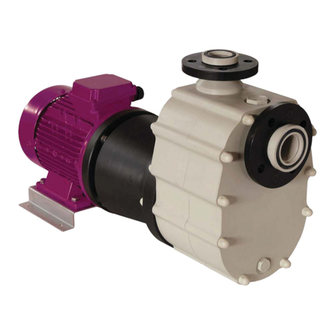
Affetti Pumps CGV-N Manual

MANUAL OF INSTRUCTIONS FOR THE INSTALLATION,
THE USE, THE MAINTENANCE AND THE SAFETY
OF THE VERTICAL ELECTRIC PUMPS
CGV-N
AFFETTI
Via Maroncelli n.4 – 21053 Castellanza (Va) – Italia
Tel. +39 0331 503358-505595 – Fax. +39 0331 483007
E-mail: affetti@affetti.com - Web-site: www.affetti.com

CGV-N
2
INDEX
GENERAL INFORMATION pag. 3
EXECUTION
PUMP BODY
IMPELLER
ROTOR
REAR BLOCK
INTERMEDIATE ADAPTOR
SUPPORT PLATE……………………………………………………………………………………………………………………………
MARKING
GUARANTEE AND CERTIFICATION
” “
” “
” “
” “
” “
” “
pag. 4
” “
” “
PRE - INSTALLATION pag. 5
PACKING
TRANSPORT
INSPECTION
STORING
” “
” “
” “
” “
INSTALLATION pag. 6
POSITIONING OF THE MACHINE
SUPPORT AND FIXING OF THE PUMP
CONNECTION WITH THE TUBES
CONNECTION OF THE ELECTRIC MOTOR……………………………………………………………………………………………...
CONTROL INSTRUMENTS
” “
” “
” “
pag. 8
” “
OPERATION pag. 9
START OF THE PUMP
STOP OF THE PUMP
TEMPERATURES
CAPACITY RANGE……………………………………………………………………………………………………………………………
ACUSTIC PRESSURE
” “
” “
” “
pag. 10
” “
HINTS ON CORRECT OPERATION pag. 11
PREVENTIVE MAINTENANCE
CRYSTALLIZATION OF THE PUMPED LIQUID
CHANGE OF THE PUMPED LIQUID
EVENTUAL DRY FUNCTIONING OF THE PUMP………………………………………………………………………………………...
IMPURITIES CONTAINED IN THE PUMPED LIQUID
” “
” “
” “
pag. 12
” “
TROUBLES AND EVENTUAL CAUSES pag. 13
THE PUMP DOES NOT EROGATE ANY LIQUID
THE PUMP DOES NOT GIVE SUFFICIENT CAPACITY
THE PUMP WORKS UNDER INSUFFICIENT PRESSURE
THE PUMP IS DISCONNECTED AND STOPS EROGATION
THE PUMP ABSORBS AN EXECESSIVE POWER
THE PUMP CAUSE VIBRATION AND NOISE
THE GUIDE BUSHES OF THE SHAFT GET RAPIDLY WORN OUT…………………………………………………………………..
SHORT LIFE OF THE MOTOR OR SUPPORT BEARINGS
” “
” “
” “
” “
” “
” “
pag. 14
” “
CROSS SECTIONS pag. 15
PART LIST…………………………………………………………………………………………………………………………………….. pag. 20
MAINTENANCE AND REPAIR OPERATIONS pag. 21
REMOVAL FROM THE PLANT
DISASSEMBLY OPERATION OF THE PLANT
ASSEMBLY PROCEDURE OF THE PUMP………………………………………………………………………………………………..
RECOMMENDED SPARE PARTS………………………………………………………………………………………………………….
DISPOSAL
” “
” “
pag. 23
pag. 24
” “

CGV-N
3
GENERAL INFORMATION
EXECUTION
The pumps of this series have been developed for the pumping of corrosive liquids and special attention has
been dedicated to a rugged construction, an easy access for maintenance and hydraulic efficiency.
The design of the volute and at the same time of a bladed channel guarantees a maximum output with
minimum overall dimensions and excellent performances.
Each machine is combined with a series of motors of different power and satisfies the most diversified needs
thanks to an optimum ratio between capacity and head in function of the specific weight of the pumped liquid
assuring a low energy consumption.
The installed motors are in compliance with the UNEL-MEC standards, mount a protection according to
IP55, are built in insulation class F and are connected with the pump body through a cast iron adaptor.
PUMP BODY
The pump body is equipped with a volute and the suction orifice is located in an axial position whilst the
delivery orifice is in a tangential position (from the machine type 65-125 to type 125-250 it is positioned in the
centre) and this is corresponding to the normal requirements of this type of plant.
On some machines the connections can be equipped with free flanges (UNI 2223 or a similar product) and
on other machines with cylindrical gas threadings.
IMPELLER
The impeller is open and on request or if necessary can be mounted a closed type. The blades on the rear
side provide for a reduction of the axial thrust caused by the flux of the liquid during suction.
ROTOR
On the CGV-N series the rotor is driven and held by means of grease-Iubricated ball bearings. The
connection between the shaft and the motor is established by means of an elastic joint.
The guide of the rotation system is performed by sleeves, which are mounted onto every joint of the column
and into the upper part of the pump body.
A plastic coating entirely covers the shaft, which is constructed in one piece and driven by bushes of pure
aluminium and freely turns inside sleeves of charged PTFE (this system varies according to the series and
the length of the immersion tube).
Their lubrication is guaranteed by the pumped liquid or by an auxiliary one coming from an external source.
REAR BLOCK
The rear block is deep and has been studied to contain the drive sleeves of the shaft, which can be replaced
very easily after wear or after rupture.
INTERMEDIATE ADAPTOR
The intermediate adaptor has got a sturdy construction and is entirely composed of cast iron. It has been
specially designed to keep the electric motor in a distance from the rest of the pump and to guarantee the
integrity of its external structure and above all of its internal parts like bearings and the rotor.

CGV-N
4
SUPPORT PLATE
The support plate is entirely manufactured of a technopolymer and assures a perfect stability and a solid
anchorage of the pump to the vat or to the tank.
If necessary, on request or in special cases, it can be equipped with a metallic counter-plate to reach a
higher compactness.
MARKING
Each machine is equipped with a label on which you find all the data prescribed by the Machine Decree CE
89/392 and which facilitates the identification of the machine.
For an eventual spare part request please cite the machine number of the pump.
GUARANTEE AND CERTIFICATION
Automatically and without a special request of the customer our company emits a guarantee and a test
certificate.
Moreover we are ready to supply all possible types of certificates according to the requirements of our
customers.

CGV-N
5
PRE - INSTALLATION
PACKING
The structure of the packing and the employed materials are chosen according to shape, dimensions and
weight of the machine, which has to be shipped.
We may adopt solutions of the following type:
−cardboard box with filling material for machines of small dimensions ;
−cardboard box and wooden pallet with filling material for bigger pumps ;
−wooden pallets exclusively for machines, which due to their structure do not need any external covering;
−wooden box for long and very heavy pumps.
TRANSPORT
A good transport is very important for the fine functioning of the machine and for this reason this operation
merits our full attention.
The charge and the discharge of the delivered items have to be performed in dependence on the shape, the
weight and the type of packing.
The lifting should be done without soliciting the fragile parts (body and connections) of the pump. The
packed machine should be set down gently and without a blow and has to be fixed and supported so that
during transport it does not leave its original position and is not exposed to strong vibrations.
The discharge in the customer's store has to be performed with the same precautions as the charge.
INSPECTION
At the arrival of the machine has to be carried out an accurate inspection to make sure that during transport
did not occur any damage. If this should be the case, please contact the responsible agent.
Sometimes -for safety reasons -components and accessories are separately packed inside the main
packing.
After the removal of the pump please accurately check the contents of the packing.
Our company is free from any obligation to reply on a request of compensation for damages advanced by
the customer or third persons.
STORING
Normally the pump is delivered with the objective of a short-term installation.
If a long storing period is foreseen, please make sure that the storing site is dry and clean in order to avoid
damages before installation.
In the cited case we advise that before its installation on the plant the pump should be carefully cleaned by
eliminating eventual foreign bodies, which could compromise the correct functioning. At last have to be
removed the protection taps from the delivery and suction orifices.

CGV-N
6
INSTALLATION
POSITIONING OF THE MACHINE
The pump has to be mounted vertically and in the best possible position to assure an easy connection with
the delivery tube. The machine should be positioned in immediate neighbourhood of the vat or tank so that a
rapid intervention is guaranteed in case of preventive maintenance or damage. It is recommended to
position the pump taking into consideration that the distance between the suction orifice, the ground and the
nearest wall should not be less than 5 times the diameter of the orifice itself.
Recommended Safety Measures
Above all you have to keep a sufficient safety distance between the machine and an eventual
passage for persons. Do not store the pump in spaces together with inflammable or explosive
materials. To assure the safety of the operator or any other interested person the positioning of the
pump should be performed by taking into consideration eventual ruptures of the delivery tube or
overflows of highly corrosive liquid during operation under pressure. Before the installation of the
machine please make sure that the switch is in the "zero" position (OFF) and disconnect the
appliance from the power supply to avoid the accidental actuation of the moving parts.
These operations should be performed only by specialized and trained staff.
SUPPORT AND FIXING OF THE PUMP
They have to be realized with suitable materials to guarantee the stability and the resistance against
eventual exhalations of corrosive vapours from the liquid in the vat or the tank. For the above-mentioned
reasons we recommend to construct the support on which the machine is positioned of stainless steel
according to AISI 316.
At first please carefully prepare the support surface. The pump is introduced into the tank and delicately put
into the right position on the support after having applied the filter or the extension tube (if requested).
Compensate the level by introducing metal shims (AISI 316) between the support plane and the plate so that
the flatness error is limited to 1 mm.
Finally connect the pump rigidly with the support by using the holes applied on the rectangular flange.
CONNECTION WITH THE TUBES (Fig.1)
The delivery tube, which is connected with the mouthpiece of the machine, should not produce any
excessive charges or disproportions.
Elevated forces and excessive movements transmitted to the tube may cause damages on the pump. For
this reason we recommend to use brackets and rigid fixations for the pressure collector. This operation is
essential and indispensable, if you want to obtain a correct operation of the machine.
Another special requirement, which should be strictly observed, is the parallelism between the flange of the
tube and the electric pump. A faulty positioning could cause forced unnatural alignments of the connected
collector and subsequently this could result in leaks on the gaskets or even cracks on some tracts of the
tube.
As already explained in the previous paragraph the application of filter on the suction side is extremely useful
to assure that eventual foreign bodies, which are present in the liquid, do not come into contact with the
impeller and the internal pump body.
Moreover we think that it is highly recommendable to mount a filter case onto the filling tube of the tank.
There should also be mounted two probes, one for the maximum and one for the minimum level. They

CGV-N
7
indicate when the water has reached the maximum or minimum height that is necessary to cover the pump
body and the eventual intermediate flanges and keep it from overflowing the vat or the tank.
If the machine includes an external flow line with an electro-valve, the cleaning and the lubrication of the
guide sleeves of the shaft is guaranteed by the total insulation of its tract. (This operations is recommended,
if the pump is installed in environments where the temperature may fall to less than 3 CC).
On the delivery have to be applied at a distance, which corresponds to 5 times the section of the tube
passage, a sluice valve and a no-return valve and, if the liquid is hot and the tube too long, a dilatation joint.
(A) Pump (K) Flow line
(B) Manometer (L) Supply vat
(C) Filter (M) Delivery tube
(D) Bracket (N) Motor
(E) Electro-valve (O) Delivery valve
(F) Filter (P) Pressure gauge
(G) Dilatation joint (Q) Electric control board
(H) Charge tube (R) Check valve
(I) Minimum level probe (S) Thermometer
(J) Maximum level probe
L
A
K
E
P
Q
N
R
M
C
O
220 mm
min.
B
H
D
S
I
J
FIG.1

CGV-N
8
CONNECTION OF THE ELECTRIC MOTOR
We advise to follow with care the schemes of the motor producer, which you can find in the terminal box or
in the instruction manual.
Recommended Safety Measures
It is highly dangerous to start the pump before having completed the installation. The assembly
operations have to be performed by specialized and trained staff.
CONTROL INSTRUMENTS
To guarantee a correct functioning the machine should be equipped with instruments, which at every instant
control its operation, i. e.
−A manual vacuum gauge installed in the immediate neighbourhood of the exit orifice for the measurement
of the operating pressure.
−A wattmeter or an ammeter for the examination of the input power and the comparison of the values
indicated on the motor label with the effectively absorbed energy.
−A thermometer for measuring the temperature of the liquid. This parameter is very important and has to
be kept under control to avoid the exposure of the machine to excessive temperatures, which could
damage the materials of the pump (see paragraph "TEMPERATURES" ).
−A pressure gauge or an automatic safety device, which blocks the pump in case of operation without
liquid, or two probes, one for the minimum and one for the maximum level, which are applied to the
supply vat or tank.
−In any case you should carefully follow the instructions of installation put at your disposal by the producer
of the appliance.

CGV-N
9
OPERATION
START OF THE PUMP
Before starting the pump you should take the following steps:
a) Please make sure that the delivery tube is correctly connected and that the bolts are well tightened.
b) Please check if in the vat there is the liquid, which has to be pumped, and that its level is at least high
enough to cover the whole body of the pump.
c) Close the exclusion valve on the delivery tube. If the pump is equipped with an external flow line, please
open the tap and make sure that before the start of the pump the liquid reaches the guide sleeves of the
machine capacity of 5 l/min. for every element that is flowed through and pressure of + 0,5 Bar compared
with the operating pressure, if the bush, which has to be flowed through, is situated at the back of the
pump body.
d) After having completed the phases (a), (b) and (c) please make sure that the sense of rotation of the
motor is correct (see arrow on the cap) by actuating the switch with a rapid sequence of start and stop.
Please do not insist on making the pump turn in the inverse sense, since this operation could cause
serious damages on the machine.
To change the sense of rotation you only have to invert two of the three terminal wires of the motor.
e) Start the motor and slowly open the exclusion valve on the delivery until you reach the required capacity
for operating the pump. (Please do not leave the sluice valve of the pressure tube closed for a long time).
f) Check the input values of the pump by taking into consideration the values marked on the motor label
and make sure that these values (input power in kw or intensity in ampere) are not exceeded.
STOP OF THE PUMP
If the delivery tube is equipped with a check valve, the stop of the machine may take place without any
particular precaution.
In the negative case the delivery valve has to be slowly closed before stopping the motor so that water
hammers in the pressure system are avoided and the liquid can flow out through the pump. Only at this point
you may close the eventual auxiliary flowing from an external source, provided that the machine is equipped
with such a device. We recommend short periodical operating controls of the pump.
Recommended Safety Measures
In the start as well as in the stop phase of the pump the operator should be adequately equipped for
reasons of health preservation.
This means rubber gloves and boots, anti-acid overalls, helmet with protective visor for the face and
the indispensable equipment for each operator, which excludes the risk of physical damages.
It is absolutely forbidden to introduce the fingers or other parts of the body into the orifices and the
various openings. The pump is equipped with movable parts.
The mentioned operations have to be performed by skilled staff.
TEMPERATURES
For the correct operation of the machine should be observed the following temperature values, which are
listed on the data sheet. Moreover we indicate the maximum and minimum operating temperatures, which
have to be strictly observed for a continuous working cycle of eight hours.
PP = -10° C + 75° C
PVDF = -40° C + 90° C
The relative material is specified on the data sheet, on the delivery bill and on the invoice.

CGV-N
10
CAPACITY RANGE
The choice of the type of pump, impeller and motor takes place at the moment of ordering by taking into the
consideration the capacity and head data requested by the customer.
The user should carefully observe the operating conditions mentioned on the data sheet and especially the
data regarding capacity and head at the operating point to which the machine has been destined.
Please do not force the pump to work in the two extreme positions, i.e. too far on the right hand or too far on
the left hand of the characteristic line, since serious problems might arise. For this reason we recommend to
work with the intermediate point of the curve.
ACOUSTIC PRESSURE
If the present product is used in an appropriate and a permanent way, the noise exposure, which depends
on the relative environment, may reach maximum values of no more than 80 dB (A).

CGV-N
11
HINTS ON CORRECT OPERATION
PREVENTIVE MAINTENANCE
The performances of the pump depend on the number of working hours, the materials used for its
construction and on the care with which the pump is treated during its operative life. A daily check during
operation helps to avoid complications and assures an immediate intervention in case of damage.
−The pump has to function without vibrations or abnormal noise. If similar events should occur, please
intervene and check the status of the rotating organs like shaft, impeller, guide sleeves of the shaft,
bearings of the motor, support and if necessary replace them.
−We recommend to inject once a week a small quantity of grease by means of the greasers positioned on
the support.
The lubricant has to be replaced after 2000 operating hours (Please use special grease for bearings).
−Please control the characteristics of the pumped liquid (temperature, specific weight and chemical
composition).
If these characteristics change, the operating conditions and the performances of the machine may
change too.
−Please accurately check that changes in the pumped solution are compatible with the characteristics of
the machine by taking into account the temperature values indicated in the paragraph
"TEMPERATURES" of the present manual, while for the other parameters we advise to contact our local
reseller or our company.
−Please make sure that capacity and pressure are according to the projected values and that they have
not been subject to changes, which may negatively influence the internal parts of the pump.
−The partial rupture of the impeller blades may cause a reduction of the hydraulic performances. In this
case you have to replace the faulty part.
−The filter housing has to be checked in periodical intervals and cleaned, if necessary.
−Please make sure that the control instruments are completely efficient and that the machine always
receives the right signals.
The replacement of the damaged parts has to take place in a dry and clean environment.
CRYSTALLIZATION OF THE PUMPED LIQUID
The crystallization of liquids is a problem, which should not be underestimated. For this reason we invite the
user to ask the producer for information on the pumped product and on the minimum value at which the
liquid starts the crystallization process.
CHANGE OF THE PUMPED LIQUID
For the replacement of the pumped liquid you have to take the following measures:
−Completely empty the tube and the machine by opening the sluice valve at the delivery.
−Clean the pump internally with water or a suitable liquid by avoiding eventual chemical reactions, which
might cause irreparable damages to the machine and the operator.
−Do not discharge the solution left after the cleaning of the internal parts of the pump into the environment.
LUBRICATION
CGV pumps are delivered with the bearings filled with grease.
It is recommended to inject a small quantity of grease by means of the greaser every week.
The suggested types of grease is SHELL ALVANIA 3 or ESSO BEACON 3 or equivalent.

CGV-N
12
Recommended Safety Measures
To operate in conditions of extreme safety during the control of the running machine the operator
should be adequately equipped.
Rubber gloves and boots, anti-acid overalls and helmet with protective visor for the face are the
indispensable equipment for the persons who have to operate without running the risk of physical
damages.
The described operations have to be carried out by skilled staff.
EVENTUAL DRY FUNCTIONING OF THE PUMP
The principal rule, which you should observe at any instant, says that with a machine of this type you must
avoid in every possible way that it functions without liquid. Only in this way you can exclude damages on the
rotating parts.
There are many situations in which this drawback might occur:
−The malfunction of the control instruments due to the encrusting and corrosive action of the pumped
liquids, which attacks the most exposed organs.
−A poor and inefficient maintenance of the filter.
−The most frequent one is the absolute or partial lack of liquid in the vat or in the tank. In this case you
should equip the machine with suitable instruments, which block the pump, if the flow of pumped liquid is
lacking (see paragraph "CONTROL INSTRUMENTS").
IMPURITIES CONTAINED IN THE PUMPED LIQUID
Due to their nature ad design the pumps of this series have got low endurance levels in case of liquids,
which contain solid, abrasive or filamentary particles.
We recommend to avoid, if possible, the pumping of such fluids or to install filters on the suction orifice and
on the filling tube of the vat. In any case you should take into consideration that the maximum allowable
concentration of impurities is 3 %. With higher values could be caused serious problems on the guide
sleeves, the impeller, the body and the internal parts of the pump.

CGV-N
13
TROUBLES AND EVENTUAL CAUSES
THE PUMP DOES NOT EROGATE ANY LIQUID
1) In the vat there is no liquid.
2) The no-return valve on the suction tube is blocked and totally closed.
3) The impeller is blocked by rubbish or incrostations contained in the liquid.
4) The total head required by the plant is higher than the projected head of the pump.
THE PUMP DOES NOT REACH A SUFFICIENT CAPACITY
5) Air enters from the suction tube due to vortexes that are caused by an insufficient immersion.
6) The passages of the impeller are partially or totally obstructed by foreign bodies.
7) The rotation speed of the motor is too low.
8) The impeller is worn out or damaged and the distance to the pump body is too big.
9) The sense of rotation is wrong.
10) The end-float between the rotating and fixed guide bushes of the shaft or between the wear ring
11) in the pump body and the impeller (only for pumps with closed impeller) has become very big.
12) The filter on the suction side is obstructed.
13) The extension tube on the suction side (if applied) has got an underdimensioned passage
section.
THE PUMP WORKS UNDER INSUFFICIENT PRESSURE
14) The viscosity of the liquid is higher than foreseen. See also points 4-6-7-8-9-10.
THE PUMP IS DISCONNECTED AND STOPS EROGATING
15) The transported liquid contains an excessive quantity of air or gas. See also points 5-11.
16) Temperature rise of the pumped liquid.
17) The capacity increased by more than the fixed value.
THE PUMP ABSORBS AN EXCESSIVE POWER
18) The specific weight or the viscosity of the pumped solution is higher than the projected values.
19) The pump performances are higher than foreseen.
20) The rotation speed is too high.
21) Damages or mechanical defects on the machine: distorted shaft, rubbing of the rotating
organs, blocked bearings of the motor and the support, etc
22) Wrong alignment of the pump group vs. the motor.
THE PUMP CAUSES VIBRATION AND NOISE
23) The flatness of the support plate has not been respected.
24) Operation at a capacity, which is too low.
25) The tube or the support structure is not rigid enough.
26) The bearings of the motor or the support are worn out or damaged. See also points 6 -20.
27) The pump is subject to cavitation, since the suction orifice has got an insufficient distance from
the ground or the wall of the vat. Please find out the reasons for the abnormal operation by
studying points 6-9-11-12.

CGV-N
14
THE GUIDE BUSHES OF THE SHAFT GET RAPIDLY WORN OUT
28) The flowing liquid or the pumped liquid contains foreign bodies or abrasive substances or the
flow duct is obstructed.
29) The gaskets or other employed materials are not suitable for the characteristics of the pumped
liquid.
30) The pumped liquid causes the formation of air or gas.
31) At the machine arrives only a small quantity of liquid or no liquid at all.
SHORT LIFE OF THE MOTOR OR SUPPORT BEARINGS
32) Lacking lubricant in the support.
33) Presence of foreign bodies in the lubricant.
34) Presence of water or condensate in the support or the motor.
35) Excessive thrust on the bearings caused by mechanical defects. See also point 20.

CGV-N
15
83
5
15
10
10
9
21
13
16
17
11
19 20 18
7
14
9
8
43
24
6
25
48 34 2247
23
12
26
67
28
60
41
42
51
40
3
23
38
31
50
80
52
75
46
84
79
39
1
2
49
82
29
53
30
56
81
54
32
57
78
55
58
76

CGV-N
16
43
10
10
9
13
17
16
11
73
34
9
67
28
6
16
14
72
70
71
67
44
8
8
7
24
52
5
6
3
40
31
23
38
50
79
80
46
84
39
75
2
1
41
36
1521 2019 18 224748
36
12
23
25
35
74
68
60
62
26
65
69
66
63
64
69
60
61
68
7
42
26
54
83
51
49
82
29
53
30
56
55
81
57
78
58
32
76

CGV-N
17
50
16
9
10
24
13
17
10
11
8
14
9
7
6
43
3
5
23
40
38
31
1
80
52
79
84
75
46
39
2
56
22
891921 8587 86 341588 48
12
42
23
47
25
60
67
28
26
51
41
82
83
29
49
53
30
81
54
55
78
32
57
58
76

CGV-N
18
6471
17
10
9
16
19
21 89 86
11
13
9
10
8587 1588 47
48 22
28
34
16
67
6
14
73
72
60
12
36
23
25
35
36
68
26
69
62
66
65
63
74
5452
8
44
70
67
7
8
24
43
6
5
3
40
31
23
38
50
68
61
69
60
26
7
41
42
51
83
49
82
30
29
53
56
46
79
80
84
39
75
2
1
57
55
81
78
58
32
76

CGV-N
19
43
24
41
7
19
31
59 89 86 87 85
1959 20
42
23
7788 15
7718

CGV-N
20
PART LIST
O-Ring74
47
46
44 O-Ring
O-Ring
Key
36
40
43
42
41
38
39
31
34
35
32
29
30
28
O-Ring
Vapour Tight Ring / Cap
Reinforced Plate
Stationary Ring
V-Ring
Screw
Head
Retaining Ring
Screw
Spacer
Tie Rod
O-Ring
Flange
O-Ring
Thrust Bearing Housing
Bushing82
Nut
Washer
Ogive
Screw
Key
Cap
86
87
89
88
83
85
84
Key
Key
Locking Nut
Wear Ring
Self-locking Nut
O-Ring
Cover
78
79
81
80
75
76
77
19
23
25
26
24
21
22
20
17
18
16
15
14
13
12
O-Ring
Impeller Lock Nut
O-Ring
Deflector
Pipe Union
Delivery tube
Impeller
Body
Stationary Bushing
Rotating Bushing
Tie Rod
O-Ring
O-Ring
Rear Block
Cap
POS.
11
10
09
08
07
06
05
03
02
01
Shaft covering
Covered Nut
O-Ring
O-Ring
Column
Covered Nut
Shaft
DESCRIPTION
Screw
Plate
Motor
Flushing Tees and Bends
Stationary Bushing
Intermediate Support
66
Cap
Covered Nut
O-Ring
Covered Nut
Tie Rod
Rotating Bushing
O-Ring
70
71
72
73
67
68
69
Screw
Stirrup
O-Ring
Spacer
Tie Rod
63
64
65
60
59
62
61
Greaser
Ball Bearing
Seal Ring
Ring Nut
Ball Bearing
Support Flange
Washer
Coupling
56
55
58
57
52
51
54
53
O-Ring
DESCRIPTION
Seal Ring
Screw
48
50
49
POS.
Table of contents
Other Affetti Pumps Water Pump manuals
Popular Water Pump manuals by other brands

Kessel
Kessel Ecolift XL Instructions for installation, operation and maintenance
Gardena
Gardena WP 600 operating instructions

VEVOR
VEVOR YMK40107A operating manual

Gormann-Rupp Pumps
Gormann-Rupp Pumps PA Series Installation, operation and maintenance manual
TLV
TLV DC3S-H instruction manual

Sealey
Sealey SMP60 instructions
Tanaka
Tanaka QCP-121 parts catalog
DAB
DAB 2 JET SET Instruction for installation and maintenance
UDOR
UDOR ZETA Series Assembly instructions
IWAKI
IWAKI TC-X400A M Series Operation manual

Villagepump
Villagepump 500 Standard Operation and maintenance manual
CDS-JOHN BLUE COMPANY
CDS-JOHN BLUE COMPANY DP-193-PP Spare parts & instruction manual

