AFG Sport 5.7AT User manual

1
5.7AT Service Manual

2
Product Browse

3
Contents
CHAPTER 1: SERIAL NUMBER LOCATION...................................................................................................5
CHAPTER 2: PREVENTATIVE MAINTENANCE
2.1 Preventative Maintenance........................................................................................................................6
2.2 Tensioning and Centering the Running Belt.............................................................................................8
CHAPTER 3: CONSOLE INSTRUCTIONS
3.1 Console Overview.....................................................................................................................................9
3.2 Display Window Indication......................................................................................................................10
3.3 Getting Started & Program Information ..................................................................................................10
CHAPTER 4: ENGINEERING MODE
4.1 Engineering Mode...................................................................................................................................13
4.2 Engineering Mode Overview...................................................................................................................13
CHAPTER 5: TROUBLESHOOTING
5.1 Electrical Diagram................................................................................................................................15
5.2 MCB Wiring Instructions.......................................................................................................................16
5.3 Troubleshooting ...................................................................................................................................17
5.3.1 No Power to the Console.........................................................................................................17
5.3.2 Safety Key Does Not Function.................................................................................................18
5.3.3 No Response from Machine (Console & Motor) ....................................................................19
5.3.4 Incline Motor Issues.................................................................................................................20
5.3.5 Noise Issues.............................................................................................................................21
5.3.6 Speaker / Audio Issues............................................................................................................23
5.3.7 Heart Rate Function Issues .....................................................................................................26

4
CHAPTER 6: PARTS REPLACEMENT GUIDE
6.1 Motor Cover Replacement...................................................................................................................26
6.2 Rear Roller Replacement.....................................................................................................................27
6.3 Side Rail Replacement.........................................................................................................................28
6.4 Running Deck Replacement ................................................................................................................29
6.5 Front Roller Replacement....................................................................................................................30
6.6 Running Belt Replacement ..................................................................................................................31
6.7 Motor Control Board (MCB) Replacement...........................................................................................32
6.8 Motor Replacement..............................................................................................................................33
6.9 Drive Belt Replacement .......................................................................................................................34
6.10Incline Motor Replacement ................................................................................................................35
6.11Console Replacement........................................................................................................................36
6.12Heart Rate Board Service..................................................................................................................37

5
CHAPTER 1: Serial Number Location
1.1 Serial Number Location

6
CHAPTER 2: Preventative Maintenance
2.1 PREVENTATIVE MAINTENANCE
Preventative maintenance is the key to smoothly operating equipment, as well as keeping the user’s liability to
a minimum. Equipment needs to be inspected at regular intervals. Defective components must be replaced
immediately. Improperly working equipment must be kept out of use until it is repaired. Ensure that any
person(s) making adjustments or performing maintenance or repair of any kind is qualified to do so.
EVERY DAY (DAILY)
Clean and inspect, following these steps:
•Turn off the treadmill with the ON / OFF switch, then unplug the power cord at the wall outlet.
•Wipe down the running belt, deck, motor cover, and console casing with a damp cloth. Never use
solvents, as they can cause damage to the treadmill.
•Inspect the power cord. If the power cord is damaged, stop using and contact Customer Technical
Support.
• Make sure the power cord is not underneath the treadmill or in any other area where it can become
pinched or cut.
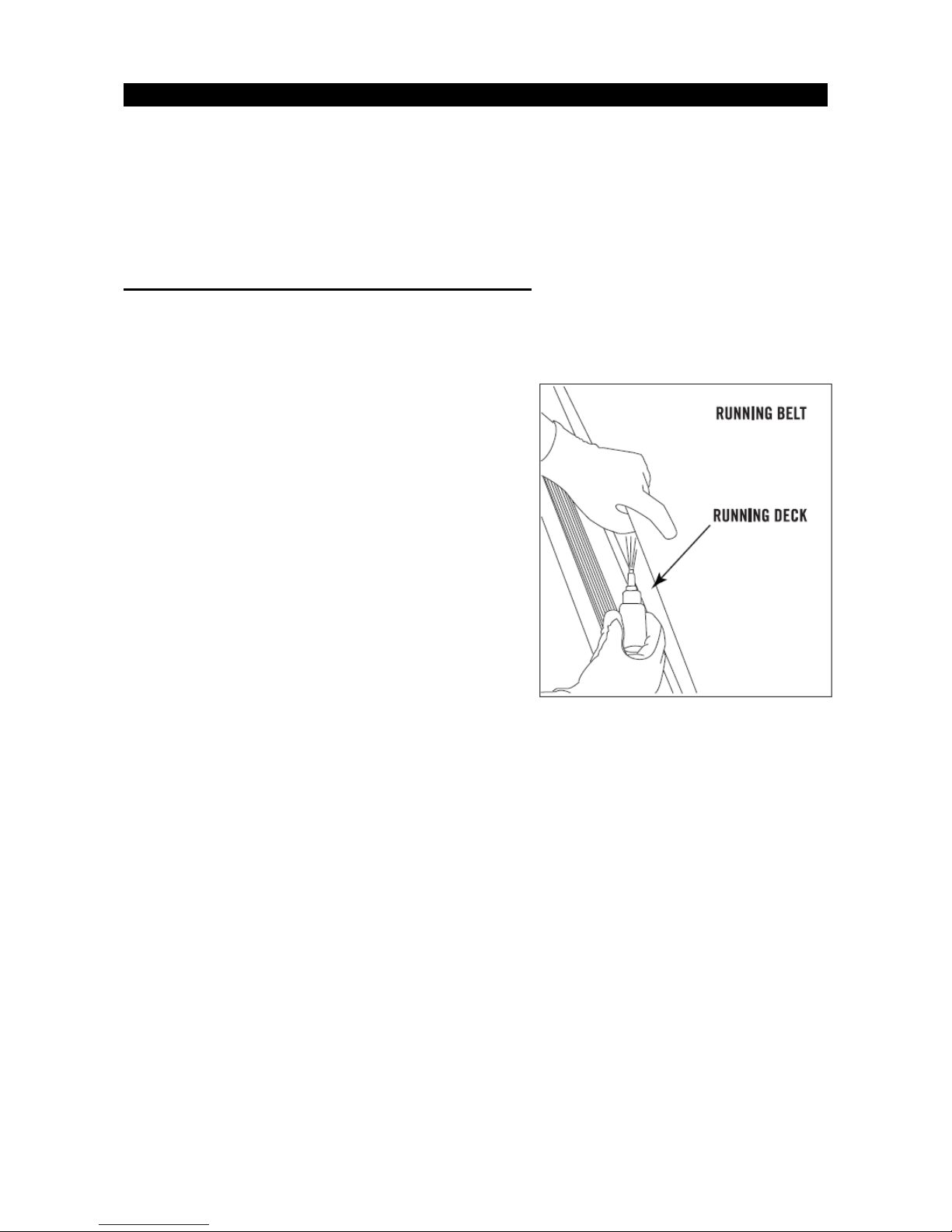
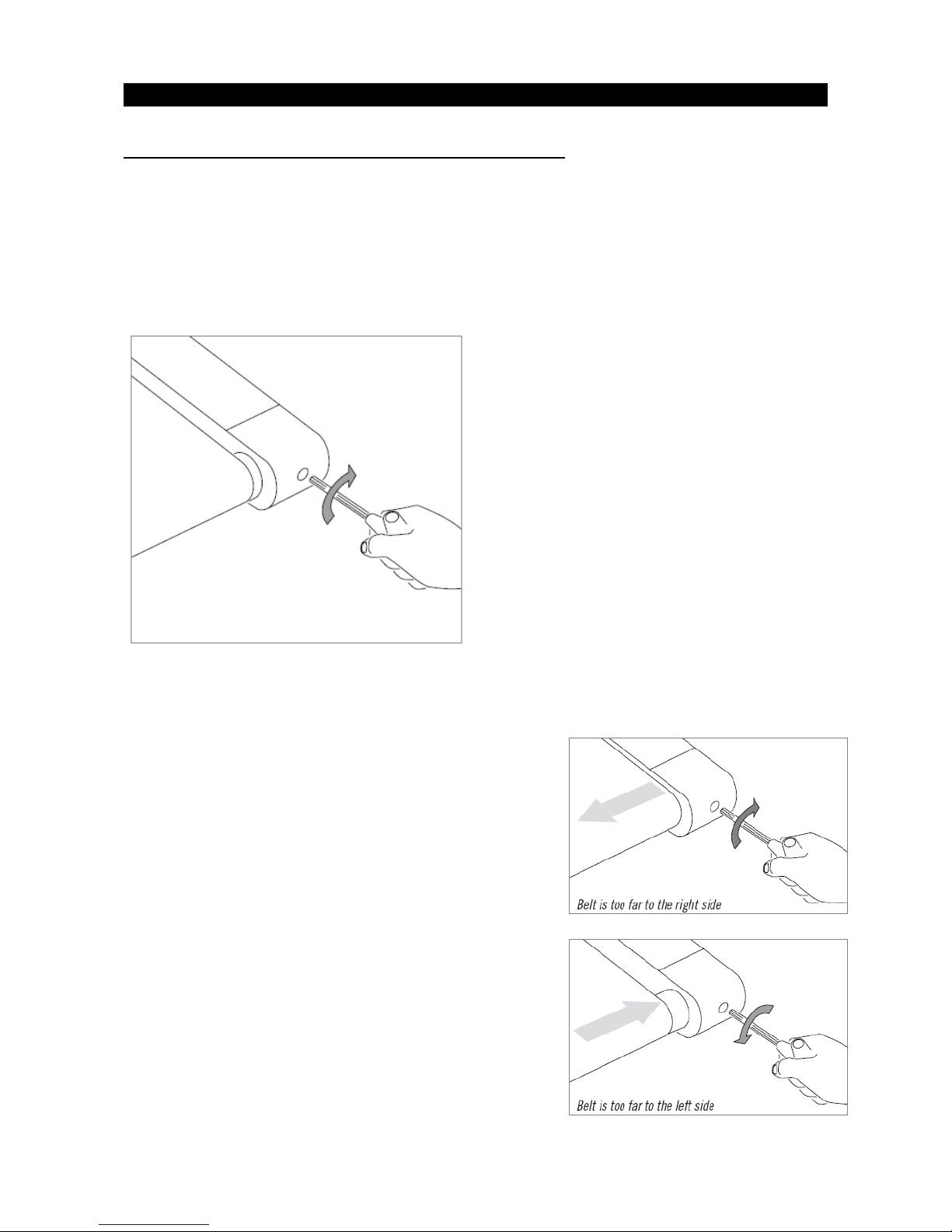
• Check the tension and alignment of the running belt. Make sure that the treadmill belt will not damage any
other components on the treadmill by being misaligned.
•If any labels are damaged or illegible, contact Customer Technical Support for replacements.
EVERY WEEK (WEEKLY)
Clean underneath the treadmill following these steps:
•Turn off the treadmill with the ON / OFF switch, then unplug the power cord at the wall outlet.
•Fold the treadmill into the upright position, making sure that the lock latch is secured.
•Move the treadmill to a remote location.
•Wipe or vacuum any dust particles or other objects that may have accumulated underneath the treadmill.
•Return the treadmill to its previous position.
EVERY MONTH - IMPORTANT!
•Turn off the treadmill with the ON / OFF switch, then unplug the power cord at the wall outlet.
•Inspect all assembly bolts of the machine for proper tightness.
•Remove the motor cover. Wait for ALL display screens to be off.
•Clean the motor and lower board area to eliminate any lint or dust particles that may have accumulated.

7
CHAPTER 2: Preventative Maintenance
Failure to do so may result in premature failure of key electrical components.
•Vacuum and wipe down the belt with a damp cloth. Vacuum any black / white particles that may
accumulate around the unit. These particles may accumulate from normal treadmill use.
2.1 PREVENTATIVE MAINTENANCE-CONTINUED
EVERY 6 MONTHS OR 150 MILES
It is necessary to lubricate your treadmill running deck every
six months or 150 miles (240 kilometers) to maintain optimal
performance. Once the treadmill reaches 150 miles (240
kilometers), the console will display the message “LUBE”or
“LUBE BELT”. The treadmill will not operate while the
message is showing. Hold ‘STOP’ for 5 seconds to suspend
message for 5 miles.
Your treadmill came with a bottle of lubricant which can be
used for two applications.
● Turn off the treadmill with the on/off switch, then unplug the
power cord at the wall outlet.
●Loosen both the rear roller bolts. For best results, place two
removable marks on both sides of the frame to note the
roller position. Once the belt is loosened, take the bottle of lubricant and using an “S” motion apply it to the
entire top surface of the running deck (including the deck surface underneath the running belt). Tighten both
rear roller bolts (matching up the marks for proper position) to their original position. After you have applied
lubricant, plug in the power cord, insert the safety key, start the treadmill and walk on the belt for two
minutes to spread the lubricant.
●Lubricate the air shocks with Teflon based spray.
●Once lubrication is complete, hold the incline ▲ and STOP keys simultaneously for 5 seconds. The
message will be cleared.

8
CHAPTER 2: Preventative Maintenance
2.2 TENSIONING & CENTERING THE RUNNING BELT
If you can feel a slipping sensation when running on the treadmill, the running belt must be tightened. In most
cases, the belt has stretched from use, causing the belt to slip. This is a normal and common adjustment. To
eliminate this slipping, turn the treadmill off and tension both the rear roller bolts using the supplied Allen
wrench, turning them ¼ turn to the right as shown. Turn the treadmill on and check for slipping. Repeat if
necessary, but never turn the roller bolts more than ¼ turn at a time. Belt is properly tensioned when the
slipping sensation is gone.
The running belt has been properly adjusted at the factory before it was shipped. At times the belt can move
off-center during shipment. Before operating the treadmill, make sure the belt is centered and remains
centered to maintain smooth operation.
If the running belt is too far to the right side: With the treadmill
running at 1 mph, turn the left adjustment bolt counter-clockwise
¼ turn at a time (using the supplied Allen wrench). Check the belt
alignment. Allow belt to run a full cycle to gauge if more
adjustment is needed. Repeat if necessary, until the belt remains
centered during use.
If the running belt is too far to the left side: With the treadmill
running at 1 mph, turn the right adjustment bolt counter-clockwise
¼ turn at a time (using the supplied Allen wrench). Check the belt
alignment. Allow belt to run a full cycle to gauge if more
adjustment is needed. Repeat if necessary, until the belt remains
centered during use.

9
CHAPTER 3: Console Instruction
3.1 CONSOLE OVERVIEW
CONSOLE OPERATION
Note: There is a thin protective sheet of clear plastic on the overlay of the console that should be removed before use.
A) LED DISPLAY WINDOWS: time, distance, calories, heart rate, speed, and incline.
B) TARGET LED INDICATORS: indicate what target (if any) is set for the current program.
C) WORKOUT LED INDICATORS: indicate what workout is set for the current program.
D) SELECT TARGET/WORKOUT KNOB: rotate/press to select your desired workout/target
E) START: press to begin exercising, start your workout, or resume exercising after pause.
F) STOP: press to pause/end your workout. Hold for 3 seconds to reset the console.
G) INCLINE KEYS: used to adjust incline in small increments (0.5% increments).
H) SPEED KEYS: used to adjust speed in small increments (0.1 mph increments).
I) INCLINE QUICK KEYS: used to reach desired incline more quickly.
J) SPEED QUICK KEYS: used to reach desired speed more quickly.
K) FAN KEY: press to turn fan on and off.
L) FAN: personal workout fan.
M) SPEAKERS: music plays through speakers when your CD / MP3 player is connected to the console.
N) AUDIO IN JACK: plug your CD / MP3 player into the console using the included audio adaptor cable.
O) AUDIO OUT / HEADPHONE JACK: plug your headphones into this jack to listen to your music through the

10
CHAPTER 3: Console Instructions
headphones.
Note: when headphones are plugged into the headphone jack the sound will no longer come out through the speakers.
P) USB INPUT: 1A/5V USB output power.
Q) WATER BOTTLE POCKETS: holds personal workout equipment.
R) TABLET/READING RACK: holds tablet or reading material.
S) CHANGE DISPLAY: changes display level between top and bottom row.
3.2 DISPLAY WINDOWS INDICATION
•
TIME:
Shown as minutes : seconds. View the time remaining or the time elapsed in your workout.
•
DISTANCE:
Shown as miles. Indicates distance traveled or distance remaining during your workout.
•
SPEED:
Shown as MPH. Indicates how fast your walking or running surface is moving.
•
INCLINE:
Shown as percent. Indicates the incline of your walking or running surface.
•
CALORIES:
Total calories burned or calories remaining left to burn during your workout.
•
HEART RATE:
Shown as BPM (beats per minute). Used to monitor your heart rate (displayed when contact is made
with both pulse grips).
3.3 GETTING STARTED & PROGRAM INFORMATION
GETTING STARTED
1) Check to make sure no objects are placed on the belt that will hinder the movement of the treadmill.
2) Plug in the power cord and turn the treadmill ON. (The ON/OFF switch is next to the power cord.)
3) Stand on the side rails of the treadmill.
4) Attach the safety key clip to part of your clothing making sure that it is secure and will not become detached during
operation.
5) Insert the safety key into the safety keyhole in the console.
6) You have two options to start your workout:
A) QUICK START UP

11
CHAPTER 3: Console Instructions
Simply press the START key to begin working out.
Time, distance, and calories will all count up from zero. OR...
B) SELECT A WORKOUT OR TARGET
1) Select your USER by turning the workout knob and then pressing when your desired USER is displayed.
2) Select your WEIGHT by turning the workout knob and then pressing when your desired WEIGHT is displayed.
3) Select your PROGRAM by turning the workout knob and then pressing when your desired PROGRAM is displayed.
4) Adjust the SETTING by turning the workout knob and then pressing when your desired SETTING is displayed.
5) Press START to begin.
WORKOUT PROFILES
1) MANUAL
: Adjust your speed and incline manually during your workout.
2) INTERVALS
: Improves your strength, speed and endurance by increasing and decreasing the speed throughout your
workout to involve your heart and other muscles. Includes 10 levels.
Speed changes and segments repeat 90 seconds and 30 seconds.
3) WEIGHT LOSS:
A workout designed specifically to target fat. Promotes weight loss by increasing and decreasing the
speed and incline, while keeping you in your fat burning zone. Includes 10 levels.
Speed and Incline changes, segments repeat every 30 seconds.

12
CHAPTER 3: Console Instructions
TARGET PROFILES
1) TARGET 1 – DISTANCE: Push yourself and go further during your workout with 13 distance workouts.
Choose from 1 mile, 2 miles, 5k, 5 miles, 10k, 8 miles, 15k, 10 miles, 20k, half marathon, 15 miles, 20 miles
and marathon goals. User sets starting speed and incline levels.
2) TARGET 2 – CALORIES: Set goals for burning calories with nine workouts. Choose from 100, 200, 300, 400,
500, 600,700, 800, or 900 calorie burn workouts. User sets starting speed and incline levels. Calories burned
are calculated using weight input of user profile.
TO RESET THE CONSOLE
Hold STOP key for 3 seconds.
FINISHING YOUR WORKOUT
When your workout is complete, the unit will beep. Your workout information will stay displayed
on the console for 30 seconds and then reset.
USING YOUR CD / MP3 PLAYER
1) Connect the included AUDIO ADAPTOR CABLE to the AUDIO IN JACK on the top right of the console and
the headphone jack on your CD / MP3 player.
2) Use your CD / MP3 player buttons to adjust song settings.
3) Remove the AUDIO ADAPTOR CABLE when not in use.
4) If you don’t want to use the SPEAKERS, you can plug your headphones into the AUDIO OUT JACK at the
bottom of the console.
AFG TABLET CONNECTED FITNESS SYSTEM
Your AFG machine is tablet ready, allowing you to use Bluetooth technology to wirelessly connect your tablet
to your AFG sport treadmill. Using the free downloadable AFG Fitness app will enable you to control your
treadmill’s operating functions via your tablet. The app will also allow you to monitor your workout, track your
progress and view your workout
history. The AFG Fitness app can be downloaded from either the iTunes store for IOS devices or from the
Google store for Android devices.
For information about connecting your tablet to your AFG Sport treadmill,
setting up the AFG Fitness App and controlling and monitoring your workout
with your tablet, see the AFG Connected Fitness Manual included with your
treadmill.

13
CHAPTER 4: Engineering Mode
4.1 ENGINEERING MODE
1. The key combination to enter the engineering menu varies by model and machine type.
1.1 Treadmill with powered elevation motor: incline up + speed down
1.2 Treadmill without powered elevation motor: speed up + speed down
1.3 Bike, elliptical, and ascent trainer without powered elevation motor: resistance up + resistance down
1.4 Elliptical and ascent trainer with powered elevation motor: incline up + resistance down.
2. Some of machines do not have certain engineering menus. The console displays “NA” or “NOT
AVAILABLE” when these menus are selected.
4.2 ENGINEERING MODE OVERVIEW

14
CHAPTER 4: Engineering Mode
Eng 0
“Eng0” appears in the
time window.
“DISPLAY TEST”
scrolls in matrix or is
static in text box.
Eng 1
“Eng1” appears in
the time window.
“HARDWARE TEST”
scrolls in matrix or is
static in text box.
Eng 2
“Eng2” appears in
the time window.
“NOT AVAILABLE”
scrolls in matrix or is
static in text box.
Eng 3
“Eng3” appears in
the time window.
“SWITCH
FUNCTION” scrolls
in matrix or is static
in text box.
1. Standard or Metric selection.
- P1 flashes in left top window
- Switch MILE or KM using Start or +/- button
- The display will show “0” for miles or “1” for km on the right top window OR
- The display will show “STANDARD” or “METRIC” statically in the middle of
text box
- Press Enter to save selection and go to language selection
2. Language selection
- P2 flashes in left top window
- Use +/- button to select language
- The display will scroll newly selected language when key is
pressed.
- Press Enter to save selection and go to machine selection
3. Machine selection
- P3 flashes in left top window
- Use +/- button to select a machine type from Treadmill, Elliptical,
Bike and Ascent trainer.
- Scroll the full name in matrix or static in the middle of text box.
- Press Enter to go to model selection
4. Model selection
- P4 flashes in left top window
- Use +/- button to select a model from the narrowed down model
list.
- Scrolls the mode name in matrix or static in the text box.
- Press enter to save the selection and go to energy saver selection
5. Energy mode selection.
- P5 flashes in left top window
- Use +/- button to switch between ON/OFF
- Display ON/OFF in the right top window OR
- Scrolls “ENERGY SAVER ON” or “ENERGY SAVER OFF” in
matrix or text box.
- Press enter to save the selection and go to first boot selection.
6. First Boot selection
- P6 flashes in left top window
- Switch “First Boot” Flag using +/- button
- The display will show “0” for OFF or “1” for ON statically on the right side OR
- The display will show “ON” or “OFF” statically on the right side when +/- button
is pressed to change
- Press enter to save current setting and back to standard or metric
selection.
Press
Enter to
Select
Press
Enter to
Select Press
Enter to
Select
Press
Start to
Begin
Eng 4
“Eng4” appears in
the time window
“INFORMATION”
scrolls in matrix or is
static in text box
1. Accumulated information
- Time window will show accumulated
time.
- Distance window will show
accumulated distance.
- Press enter to review software
version
2. Software version
- Display the UCB software version the
same way as powering up.
- Press enter to review MCB version
3. MCB version
- Display the MCB version on screen in
an appropriate way.
- Press enter to navigate back to
accumulated information
Press
Enter to
Select
1. All light up as default.
2. Stop turns off all lights
3. Start turns on all lights
4. All numerical displays
increase by 1 when speed
up is pressed.
5. All numerical displays
decrease by 1 when speed
down is pressed
6. All alpha-numerical
displays change from A to Z
after each incline up key
press
7. All alpha-numerical
display change from Z to A
after each incline down key
press
8. Matrix display lights one
row up from bottom to top if
a up arrow key is pressed.
9. Matrix display lights one
row up from top to bottom if
a down arrow key is
pressed.
10. All the other keys or if
there is a key without an
associated display defined
as above, display the
physical key matrix as
“Cxdx” in the left top window
and key code in the right top
window.
1. Basic functions test
-Speed +/- change speed.
- Speed quick keys change speed.
Preset to be within 20%.
- Display speed in speed/left top
window, Display PWM in distance/
right top window
- Incline +/- change incline.
Quick incline keys beep but do not
function.
- Incline motor to stop at min or
max (not continue to move) if +/-
held.
- Display incline value in incline
window.
- Display heart rate value when
heart rate detected.
- Press enter to go to USB port
test
2. USB port test
- “USB PORT TESTING...” scrolls
in matrix or is static in text box.
- “PASS” scrolls in matrix or is
static in text box if passed test. OR
“FAIL” scrolls in matrix or is static
in text box if failed in test.
Eng 8
“Eng8” appears in the
time window.
“TEST” scrolls in
matrix or is static in
text box
1. Program accelerator
- P1 shows in the left top window
- The multiple of program time defaults to 1 and
display in the time window or right top window.
- Press +/- to change it from 1 to 100.
- Press enter to save the settings and navigate to
next mode.
2. Clear user’s data
- P2 shows in the left top window
- Clears Accumulated time and distance, and change
to the default value in ENG8, in Puser, in elog, in
RCT, and so on .
- The Brickyard will scroll “CLEAR” or “ NO CLEAR”.
- if there is no matrix, the TIME window show “0”
for “CLEAR ”or “1”for “NO CLEAR”.
- If the data is not cleared, hold START for 5s to
clear.
- Press ENTER to set to next mode P4.
3. Burn-in period check
- P3 shows on left top window
- Burn-in period appears in time window with unit hour
- Press ENTER to set next mode “P5”,
4. Quick Standby mode access
- P4 shows on left top window
- The Brickyard will scroll “PRESS START BUTTON
TO ENTER STANDBY MODE”
- Press Start button to enter standby model instantly.
- Press Enter again to skip and navigate to “P0”
mode.
Press
Enter to
Select
Note:
1. USB port testing is only for the consoles which have USB interface.
2. First Boot flag is only used for consoles which work for different machine and/or model types.
3. A text box must be implemented when multi language is available.
4. Console goes to model selection after cycling the power when First Boot flag is set to ON.
5. If there is confliction between process number “Px” and other display items, the process number will only display
for 1 second and then display the real items.
6. Display items alternatively when a few items needs to be displayed in the same window. Light up the indictor if the
indicator exists.
7. A text box or LED/LCD matrix is needed if the console work for different machine and/or model types.

15
CHAPTER 5: Troubleshooting
5.1 ELECTRICAL DIAGRAM
100032468

16
CHAPTER 5: Troubleshooting
5.2 MCB WIRING INSTRUCTIONS
CN1------- Power light
CN2------- AC power cable socket
CN3------- Elevation motor cable socket
CN4------- Speed sensor cable socket Console set cable socket
CN5------- Error light, near the chip
CN6----- Speed sensor cable socket

17
CHAPTER 5: Troubleshooting
5.3 TROUBLESHOOTING – NO POWER TO THE CONSOLE
NO POWER TO THECONSOLE
1) SYMPTOM:
a. The power switch is set to on, but the console does not light up.
2) SOLUTION:
a. Check the power cord’s connection.
-If the power cord connected well but the console doesn’t turn on, try a different power cord.
b. Check if the outlet is well.
-If it is not, please try a different, functional outlet.
c. Check if the MCB has power. There is a red power LED on the MCB that should be lit.
d. If the MCB does not have power, check the connection of the power wiring from the power receptacle
to the MCB. Use a multi-meter to measure AC1 & AC2. The AC voltage should read 110V or 240V,
depending on your location’s standard voltage.
-If AC voltage value is standard, replace the MCB.
e. If the MCB does have power, check the connection of the console cable wire at the MCB and UCB.
-Remove the console cable from MCB, and use a multi-meter to measure the DC voltage between the
“GND pin” (Pin 1&2) and the “+ 12V Pin” (Pin7 & 8). DC output is normally around DC 12V. If no output,
replace the MCB.
-If output is around DC 12V, check the console cable. If it is defective, replace the console cable.
-If the console cable connections are all good, replace the PCB.

18
CHAPTER 5: Troubleshooting
5.4 TROUBLESHOOTING – SAFETY KEY DOES NOT FUNCTION
SAFETY KEY DOES NOT FUNCTION
1) SYMPTOM:
a. The safety key is inserted in the console, but display window still shows “safety key off”.
2) SOLUTION:
a. Verify the safety key is fully inserted in the console.
-If it is not, detach the safety key and then insert it again.
b. Check the safety key for signs of oxidization.
-If signs are present, replace the safety key.
c. If the safety key is functional, check the safety key sensor wires in the console.
-Detach and then reconnect the wires; if the issue remains, replace the wires.

19
CHAPTER 5: Troubleshooting
5.5 TROUBLESHOOTING – NO RESPONSE FROM MACHINE (CONSOLE&MOTOR)
THEPOWER IS ON, BUT MACHINE HAS NO RESPONSE
1) SYMPTOM:
a. The power is on and the console lights up, but the treadmill does not run when keys are pressed.
2) SOLUTION:
a. Verify whether the console beeps when each key is pressed. If it does not, replace the keypads.
b. Enter Engineering Mode and scroll to ENG 1 (Hardware Test). Press the key “ENTER” first and then
the key ”START”.
- Press the key “SPEED + / -”. If the data on the windows “TIME” and “DISTANCE” is changed, the
console is ok. If the data does not change, replace the PCB.
c. Turn off the power switch and then remove the motor cover. Detach the red & black motor wires from
the MCB, and then use a multi-meter to measure the resistance from the drive motor.
-If the resistance is higher than 10 Ω, the drive motor is defective. Replace the drive motor.
-If the resistance is lower than 10 Ω, the drive motor is ok.
d. If the issue remains:
-Check the connection of the speed sensor (encoder disk group) at the MCB.
-Remove the speed sensor from the motor and clean it, then re-test.
-If the speed sensor is clean and has a good connection but still will not operate, replace the speed
sensor.
-Replace the MCB as the last step if machine does still not run.

20
CHAPTER 5: Troubleshooting
5.6 TROUBLESHOOTING - INCLINE MOTOR ISSUES
INCLINE MOTOR ISSUES
1) SYMPTOM:
a. The incline motor does not lift up or down.
2) SOLUTION:
a. Enter Engineering Mode, and scroll to ENG 1 (Hardware Test). Press the key “ENTER” first and then
the key ”START”. Press the keys “INCLINE ▲/▼”.
- If you hear clicks from two relays at the MCB, the MCB is ok. Check the connection of the elevation
motor at the MCB. Unplug and re-plug these two pins. If the issue remains, replace the elevation
motor.
- If there are no beeps from these two relays, MCB is defective. Replace the MCB.
Table of contents