AFL Hyperscale H Series User manual

Installation Guide
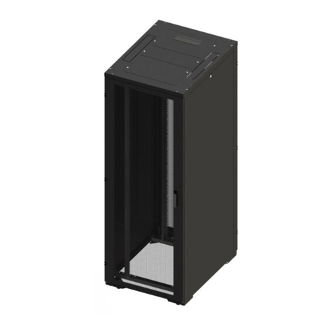
7RU Housing
Series

2© AFL Hyperscale. All rights reserved Series
Safety Precautions
Laser Precautions
Warning: The laser light used to transmit information over optical ber cables can cause severe eye
damage. Because this light is invisible, it will not cause the iris of the eye to contract involuntarily as when
viewing a bright visible light, and no pain is felt as the retina is burned.
Never look into the end of a ber or connector which may have a laser coupled to it. Should accidental
eye exposure to laser light be suspected, arrange for an eye examination immediately.
General Precautions
Personnel must be thoroughly familiarized with all applicable Occupational Health and Safety (OH&S)
regulations, local regulations, and your company safety practices and policies.
Warning: To reduce the chance of accidental injury:
Before work begins, all personnel must be thoroughly familiar with the operation of all equipment
and procedures to be used during the installation.
Before use, all equipment, especially safety gear, must be inspected and tested for proper operation.
Replace and repair as necessary.
H-Series 7RU Housing
Before installing or adjusting this product, please read these instructions carefully.
Please keep this guide for future reference.

3
H-Series 7RU Housing
© AFL Hyperscale. All rights reserved
Series
Component Overview

4© AFL Hyperscale. All rights reserved Series
In the Box
Item
Number Item Qty
01 H-Series 7RU Housing 1
02 Door Label 1
(01) H-Series 7RU Housing
(02) Door Label
Cross-Head
Screwdriver
250 μm Wrapping Tube
Cable (WTC) with SpiderWeb
Ribbon® (SWR®)
Up to 24 H-Series
Cassettes
MPO MicroCable Patch
Assembly (Single Jacket 3mm
OD)
LC Premium Uniboot Patch
Cords Reversible Polarity
M4 x 5 Screw and Nuts
(4pcs)
MicroCable Assemblies
(2mm Tails)
What You Will Need Related Products

5
H-Series 7RU Housing
© AFL Hyperscale. All rights reserved
Series
H-Series Cassette Types
H-Series Cassette Types
MPO – LC Cassette BASE-12 24f
24f Pass-Through Cassette
MPO Cassette BASE-12 144f
Blank Plate
24f LC Ribbon / Single Splice Cassette
24f Splice Only Cassette
Splice Only Cassette

6© AFL Hyperscale. All rights reserved Series
Mounting the Housing
Install the housing in the rack using the M6x16mm screws.
1
Open the front door (up to a 135º angle) and place the label on the door.
2

7
H-Series 7RU Housing
© AFL Hyperscale. All rights reserved
Series
Loading the Cassette
Install the rst cassette in the housing and secure it by pressing in the snap rivets.
Note: Make sure the incoming port or entry point is facing upwards before installing the cassette.
3
Install the remainder of the cassettes.
4

8© AFL Hyperscale. All rights reserved Series
24f LC Ribbon / Single Splice Cassette
Note: Once all the cassettes are in position, proceed to address the cable to the correct slot positions in order.
Once complete, ensure there is enough cable to proceed with the splicing.
5b
Loading the Cables
Components may vary depending on the cassette selection and application.
One slot per two
cassettes
One slot per two
cassettes
One slot per two
cassettes
One slot per two
cassettes
MPO – LC Cassette BASE-12 24f
Note: Once the MPO is connected at the top of the cassette, proceed to patch at the front and address to the
bottom ber management.
5a

9
H-Series 7RU Housing
© AFL Hyperscale. All rights reserved
Series
Remove the dust caps and load the cables as illustrated below.
Loading the Cables
24f LC Pass-Through Cassette
Note: The cassette does not come with cable assembly and has to be installed by opening the cassette and
addressing the connector inside according to customer ber mapping specications.
5c
MPO Cassette BASE-12 144f
Note: Empty cassette that can be used with MPO or FUSEConnect pre-terminated assemblies in order to land
SpiderWeb Ribbon®(SWR®) ber (12 x 12f MPO or FUSEConnect pre-terminated assemblies required for this
conguration).
5d

10 © AFL Hyperscale. All rights reserved Series
Loading the Cables
Remove the dust caps and load the cables as illustrated below.
MPO – LC Cassette BASE-12 24f and Blank Plate
Installation procedure for a blank plate is the same as the cassette.
Note: In the event that the number of cassettes required does not ll all the positions in the housing, we
recommend adding blank plates for the remaining spaces.
5e

11
H-Series 7RU Housing
© AFL Hyperscale. All rights reserved
Series
1) Separate the pigtails into two bundles of 12 as per mapping requirements.
2) Proceed to feed the incoming cable at the top of the cassette and secure using the gland.
Note: We recommend feeding up to 1.2 meters of cable.
3) Proceed to strip the cable.
Note: Leave up to 30mm of aramid yarn to secure in the holders as shown above.
4) Separate the bers in the incoming cable to match the pigtail bundle and proceed to splice.
5) Once complete, coil the rst bundle in the cassette clockwise and secure the splice protector in the bottom
splice holder (position 2).
6) Repeat the process anti clockwise for the second bundle and secure the splice protector in the top splice
holder (position 1).
7) Close the cassette and position it back in the housing.
6a
Single Splice Cassette
Wrap the aramid yarn
around the stud and
tighten by using the
spacer and nut.
Splice holder
position 1
Splice holder
position 2

12 © AFL Hyperscale. All rights reserved Series
Ribbon Splice Cassette
6b
Wrap the aramid yarn
around the stud and
tighten by using the spacer
and nut.
1) Uncoil the ribbon pigtail and separate the rst and second ribbon as per label indication.
2) Proceed to feed the incoming cable at the top of the cassette and secure using the gland. Note: We
recommend feeding up to 1.5 meters of cable.
3) Strip the cable. Note: Leave up to 30mm of aramid yarn to secure in the holders as shown above.
4) Separate the bers in the incoming cable to match the pigtail bundle and proceed to splice as per
manufacturer’s guidelines. Note: For ribbon bers, identify the rst and second ribbons before splicing.
5) Once complete, coil the rst bundle in the cassette clockwise and secure the splice protector in the splice
holder.
6) Close the cassette and position it back in the housing.

13
H-Series 7RU Housing
© AFL Hyperscale. All rights reserved
Series
For the single splice cassette, load and splice the pigtails as illustrated above. Close housing door once installation
is complete.
6c
Ribbon / Single Splice Cassettes
Magnet
Magnet
Slot Bracket

14 © AFL Hyperscale. All rights reserved Series
Notes

15
H-Series 7RU Housing
© AFL Hyperscale. All rights reserved
Series
Notes

Thank you for choosing AFL Hyperscale
AFLHSHS7RUH270820
www.aflhyperscale.com
AFL Hyperscale reserves the right to make changes in this Installation Guide at any time without notice
Table of contents
