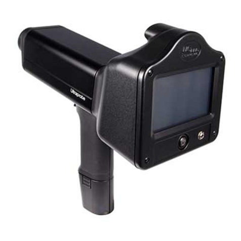
AFL FOCIS Flex User manual

AFL Confidential
FOCIS Flex
Intro to Operation
May 2017
1

FOCIS Flex Intro to Operation Outline
•What’s New in FOCIS Flex (May 2017 Update)
•Controls, Display and Interfaces
•Connector Adapter Tips
•Operation
•Power-up / Power-Down (including Auto-Off)
•AC Power and Battery Operation
•Image Display Modes
•Live Display Mode: Manual Focus, One-time Auto-focus, Auto-focus & Capture
•Captured Image Display Mode
•Main Menu Settings Mode
•Pass/Fail Analysis Settings
•Auto-focus Enable/Disable
•Bluetooth Settings
•Beeper
•Time & Date
•Saving & Sending captured images and pass/fail results
•Viewing Saved Results using Results Manager
•File Transfer via Bluetooth and USB
2AFL Confidential

Free!
What’s New in FOCIS Flex?
•Updated FOCIS Flex HW & SW!
•Brighter, larger display with power save auto-dimming
•Adds MPO/MTP Auto-focus, capture & pass/fail analysis
•Adds iOS-compatible Bluetooth with MFI chip
•Adds WiFi live video streaming (for future tablet App)
•Adds AT&T & IPC pass/fail criteria
•Updated IEC pass/fail criteria
•Configurable auto-save & auto-send
•Image-pairing (e.g. save image before & after cleaning)
•International languages
•Instant On power-up
•Inspection Reporting:Supported in TRM 2.0 &
•Included in both Basic and Advanced versions
•Free download from www.AFLglobal.com Resources Software
•TRM 2.0 now included with FOCIS Flex & FOCIS WiFi; aeRos Basic account is free
•Android & iOS FOCIS Flex Apps:
•Now available from Google Play or Apple App Store
•Accepts inspection image + pass/fail overlay via Bluetooth
•Merges image & overlay and displays on smart device
•Integrates with (Setups & Reporting)
AFL Confidential 3

FOCIS Flex
FOCIS Flex Controls, Display, Interfaces
•Controls
•On/Off Button & LED
•Capture Button
•F1 Soft Key (typically ‘Back’ function)
•F2 Soft Key (typically ‘Select’ function)
•Navigation & Edit keys
•Display
•Display Title
•Image & Information display area
•Interfaces
•Optical Inspection Port & Dust Cover
•5 VDC input jack and charging LED
•Micro-USB port
4
Capture
Button
F2
Soft Key
& Label
F1
Soft Key
& Label
Navigation
& Edit Keys
On/Off
Button
Optical Inspection
Port & Dust Cover
Display Title
2-inch
Color LCD
(320 x 240) Image
Display
Area
AFL Confidential

Connector Adapter Tips
•FOCIS Flex available with the following adapter tips:
•Removing Adapter Tips:
•Turn captive nut clockwise (viewed from front / top)
•Continue until captive nut is free of adapter tip
•Remove tip
•Installing Adapter Tips:
•Raise captive nut until it engages with adapter tip threads
•Turn captive nut counter-clockwise (viewed from front / top)
•Hand-tighten (do not over-tighten)
5
UPC Connectors APC Connectors
Connector Ferrule Bulkhead Ferrule Bulkhead
SC FFLX-01-U25 FFLX-01-SC FFLX-01-A25 FFLX-01-ASC
FC FFLX-01-U25 FFLX-01-FC FFLX-01-A25 FFLX-01-ASC
LC FFLX-01-U125 FFLX-01-LC FFLX-01-A125 FFLX-01-ALC
ST FFLX-01-U25 FFLX-01-ST Not applicable Not applicable
Tighten
Loosen
Note: For proper viewing, APC connectors must be aligned
with the slot in the threaded area of the adapter tip
AFL Confidential

Identifying Connector Adapter Tips
•Tips are engraved and shipped in labeled containers
•Engraving indicates connector type and application
•Labels indicate:
•AFL Part Number
•Connector Type –Ferrule Type (UPC or APC) –Application
•Blue ring indicates UPC connector tip; Green ring indicates APC tip
6AFL Confidential

APC Connector Orientation
APC Connector Orientation using Universal 2.5 mm APC Ferrule Adapter:
7
Good contrast image
when properly oriented
Poor contrast image if
improperly oriented
APC Connector Orientation using SC-APC Bulkhead Adapter:
Align bulkhead key slot with
slot in bulkhead adapter tip
Good contrast image
when properly oriented
Align connector key with
slot in ferrule adapter tip
AFL Confidential

Single-Row MTP/MPO Inspection
•Press to select ‘MPO-U’ or ‘MPO-A’ connector type in Live Image mode
•MPO-U: Multimode MPO with PC finish
•MPO-A: Single-mode MPO with APC finish (usually green connector)
•Base + Tip is required; Base attaches to DFS1 or FOCIS Flex
•Connectors are inspected through a bulkhead as shown
•Adjustment knob scans across row
8
Base PC Tip
“MTP”
Position control to view
fiber ends within row
APC Tip
“MTPA”
Part No.
Description
DFS1
-00-
0037MR
Base plus MPO/MTP
PC tip
DFS1
-00-
0042MR
Base plus MPO/MTP PC
& APC tips
DFS1
-01-
0010MR
Base plus MPO/MTP APC tip
DFS1
-00-
0041MR
MPO/MTP
PC tip only
DFS1
-01-
0012MR
MPO/MTP
APC tip only
8400
-00-
0093MR
MPO/MTP bulkhead (PC)
8400
-00-
0094MR
MPO/MTP
bulkhead (APC)
Single-row (12-pin)
Connector
To DFS1
or
FOCIS Flex
MPO/MTP
Bulkhead
AFL Confidential
MPO/MTP
Connector
(Ferrule)

APC Tip
“MTPA”
Multi-Row MTP/MPO Inspection
•Press to select ‘MPO-U’ or ‘MPO-A’ connector type in Live Image mode
•MPO-U: Multimode MPO with PC finish
•MPO-A: Single-mode MPO with APC finish (usually green connector)
•Connectors are inspected through a bulkhead as shown
•One adjustment knob scans across row
•Second adjustment knob selects row (up to 8 rows of 12 fibers per row
9
Base PC Tip
“MTP”
MPO/MTP
Bulkhead
DFS1-00-0050MR
Select fiber
within row
Select row
To DFS1
or
FOCIS Flex
Part No.
Description
DFS1-00-0050MR Base plus MPO/MTP PC tip
DFS1-01-0012MR MPO/MTP APC tip only
8400-00-0093MR MPO/MTP Bulkhead (PC)
8400-00-0094MR MPO/MTP Bulkhead (APC)
AFL Confidential
Multi-row MPO/MTP
Connector (Ferrule) 24-fiber, dual-row
Connector
(2 rows x 12 fibers)

FOCIS Flex MPO Support
•New, enhanced FOCIS Flex supports MPO auto-focus, capture, pass/fail analysis
•In Live Image mode, green circle identifies fiber end to be captured and analyzed
•In Captured Image mode, three zoom levels available
•Pass/Fail results table reports scratches & defects detected in A & B zones
•Supports both single-mode APC and multimode PC MPO connectors
•Uses the same MPO adapters previously utilized with FOCIS Flex & DFS1
•Results may be saved and included in TRM 2.0 or aeRos Test Reports
•Example FOCIS Flex MPO Images:
AFL Confidential 10
Live Image Captured –Zoomed Out Captured –Partial Zoom Captured –Full Zoom Pass/Fail Results

Opti-Tip / Opti-Tap Connector Inspection
•Opti-Tap Patch Cord Inspection
•Use Universal 2.5mm APC ferrule adapter tip
•Opti-Tap Bulkhead Connector Inspection
•Use DFS1-01-0007MR
•Opti-Tip Ribbon Patch Cord Inspection
•Use DFS1-01-0013MR with barrel attached
•Opti-Tip Ribbon Bulkhead Connector Inspection
•Use DFS1-01-0013MR with barrel removed
11
DFS1-01-0007MR
DFS1-01-0013MR
Barrel
AFL Confidential

FOCIS Flex
Power Switch
(Top View)
FOCIS Flex Power Up / Down
•Power-Up
•Press and release the On/Off Button
•Display immediately powers up in Live Image mode
•Power-Down
•Press and hold power button until display turns off
•Auto-Off
•From Main Menu Settings, select ‘Power Save’
•Select desired power save option (2, 5, 15 min or Never)
12AFL Confidential

FOCIS Flex
5V
FOCIS Flex AC Power & Battery Operation
•Operating from AC Power and Charging the Battery
•Plug the included AC Charger into AC outlet
•Connect charger plug into 5 VDC jack on FOCIS Flex
•Charging LED:
•Off: AC not plugged in
•Solid red: Discharged battery is being charged
•Solid green: Battery is fully charged
•Flashing red/green: Charging error.
•Verify correct 5 VDC 2A charger used.
•FOCIS Flex charges while operating
•Battery Operation
•Battery status icon indicates battery state:
•Charging, not fully charged
•Charging, fully charged
•Battery operation, fully charged
•Battery operation, partially charged
•Battery operation, <15 min operating time remaining
13
Battery
Status
Icon
AFL Confidential

Live Mode
1. FOCIS Flex powers up in Live Image mode
2. Help (?) soft key shows key functions
•Popup Help displayed (6)while ?key pressed and held
3. Press to toggle connector type (Single, MPO, MPO-Flat)
•Single = Single fiber connector inspection (UPC or APC)
•MPO-PC/APC = MPO/MTPmulti-fiber conn.; PC or APC finish
•MPO-Flat = MPO/MTP multi-fiber connector; Flat finish (rare)
4. Menu (≡) soft key selects Main Menu
5. When Auto-focus enabled & Capture ( ) pressed:
•Auto-focus is initiated
•Image is captured when auto-focus complete
•Image is analyzed if Pass/Fail enabled
•FOCIS Flex transitions to Captured Image Mode
When Auto-focus disabled:
•Press right arrow key () to Auto-focus once
•Press Up/down keys () to manually adjust focus
•Press Capture Key ( ) to capture image
•Image is analyzed if Pass/Fail enabled
•FOCIS Flex transitions to Captured Image Mode 14
2
3
6
5
1
AFL Confidential
4
3
New!

Capture Button Operation
•From Live Image Display mode:
•Press Capture to:
•Auto-focus image (if Auto-focus enabled)
•Capture image
•Analyze image (if Pass/Fail enabled)
•Enter Captured Image Display mode
•From Captured Image Display mode:
•Press Capture to return to Live Image mode
•From Main Menu or Settings modes:
•Press Capture to return to most recent Live or
Captured Image Display mode
15
Capture
Button
AFL Confidential

•Captured Image Display (Zoomed In or Out)
1. Filename (saved image) or ‘Captured @ hh:mm:ss’ (unsaved image)
2. Pass/Fail indication (Only if Pass/Fail enabled)
3. Display Tabs (select using left/right arrows [])
Zoomed Out Image
Partially Zoomed In Image
Fully Zoomed In Image
Pass/Fail Results Table
Image Information
4. Endface Image with pass/fail region overlay
Failing scratches / defects highlighted in red
Passing scratches / defects highlighted in green
5. Back softkey ()
6. Image Layers (select using up/down keys [])
Endface + Overlay (Default)
Endface only
Overlay only
7. Save/Send Menu soft key (≡)
Captured Image –Image Display
16
1
2
3
4
5 6 7
AFL Confidential
i

•Pass/Fail Results Table Display
1. Title: Filename (saved image) or ‘Captured @ hh:mm:ss’ (unsaved)
2. Pass/Fail indication (Only if Pass/Fail analysis enabled)
3. Pass/Fail display tab selected
4. Analysis Rule applied to determine pass/fail
5. Analysis Zone IDs (A, B, C, D)
6. Scratch analysis results for each zone
•Reports number of detected scratches / defects
•Failed rules highlighted in red
7. Defect analysis results for each zone
8. Back softkey ()
9. Save/Send Menu soft key (≡)
Captured Image –Pass/Fail Results
17
1
2 3
4
5 7
6
8 9
AFL Confidential

A: Core
B: Cladding
C: Adhesive
D: Contact
Passing
Defect
Failing
Defect
Understanding IEC Pass/Fail Analysis
•IEC 61300-3-35 defines connector inspection pass/fail criteria
•Pass/Fail criteria depends on:
•Fiber type (SMF or MMF)
•Connector type (Single or MPO)
•Connector finish (PC/UPC or APC)
•Connector end face regions
•A region: Core
•B region: Cladding
•C region: Adhesive
(between cladding & ferrule)
•D region: Physical contact area
•Type of end face flaw:
•Scratches
•Defects (contamination, particles)
•Size of flaw
18AFL Confidential

Example IEC Rule
•Rules provided for each region:
•When MPO/MTP connector inspected, C&D regions are not evaluated.
•Example provided for:
•Single-mode PC connector with mated connector ORL 45 dB
19
Region Scratches Defects
A: Core >0 m: 0
(No scratches > 0 m allowed)
>0 m: 0
(No defects > 0 m allowed)
B: Cladding
>3 m: 0
(No scratches > 3 m allowed)
2-5 m: 5
(Up to 5 defects 2
-5
m diameter
allowed)
>5 m: 0
(No defects > 5 m allowed)
C: Adhesive Blank
(No limitations on scratches)
Blank
(No limitations on scratches)
D: Contact Blank
(No limitations on scratches)
10 m: 0
(No defects 10 m allowed)
AFL Confidential

Device Info Display
1. Title indicates saved or unsaved results
•‘Captured @ hh:mm:ss’ if unsaved
•‘<Cable>-<Fiber>’ if saved
2. Blue highlighted area indicates default folder / file
names if results are saved
3. Time indicates Time & Date image captured
4. Rule identifies pass/fail analysis rule applied
5. Back softkey ()
6. Save/Send Menu soft key (≡)
20
1
2
3
4
5 6
AFL Confidential
Other manuals for FOCIS Flex
1
Table of contents
Other AFL Analytical Instrument manuals
Popular Analytical Instrument manuals by other brands
Teledyne
Teledyne 4020 operating & maintenance manual
CUES
CUES K2 Screen Operations
Goldanalytix
Goldanalytix GoldScreenCard instruction manual
Powerfix Profi
Powerfix Profi 288019 Operation and safety notes

Teledyne
Teledyne 328 instruction manual

Sensopart
Sensopart FT 50 RLA Series Mounting and operating instructions
