AFL IDEAA Mini Interior Distribution Cabinet User manual

1
INSTALLATION INSTRUCTIONS
IDEAA®Mini Interior Distribution Cabinet
TABLE OF CONTENTS
GENERAL .........................................................................................................................................2
SPECIFICATIONS.............................................................................................................................2
PACKAGE CONTENTS..................................................................................................................... 2
PACKAGE CONTENTS: ACCESSORIES.........................................................................................3
REQUIRED TOOLS ..........................................................................................................................3
ADD-ON COMPONENTS..................................................................................................................3
CABINET MOUNTING—WALL MOUNT ...........................................................................................3
LOCK AND UNLOCK EXTERIOR DOORS.......................................................................................4
CABLE PREPARATION .................................................................................................................... 4
CABLE INSTALLATION ....................................................................................................................5
COMPRESSION FITTING INSTALLATION ......................................................................................6
DISASSEMBLE COMPRESSION FITTING—CABLE REPLACEMENT........................................... 6
SPLICING..........................................................................................................................................6
IDEAA SPLITTER MODULE INSTALLATION—MOUNT IDEAA SPLITTER MODULE .................... 8
IDEAA SPLITTER MODULE INSTALLATION—ACTIVATE IDEAA SPLITTER MODULE ................ 9
MDU DROP CABLE INSTALLATION .............................................................................................10
IDEAA SPLITTER MODULE INSTALLATION—CONNECT DISTRIBUTION FIBER...................... 13
PASS THROUGH CONNECTION................................................................................................... 14

2
INSTALLATION INSTRUCTIONS
IDEAA®Mini Interior Distribution Cabinet
© 2016, AFL, all rights reserved. Revision 0, 4.27.17
Specications are subject to change without notice.
GENERAL
SPECIFICATIONS
The IDEAA Mini Interior Distribution Cabinet (Mini IDC) provides a convenient and extremely compact modular approach
to centralized ber distribution in small MDUs. The Mini IDC provides up to 64 home run drop output connections using
two 1x32 IDEAA Splitter Modules. The Mini IDC utilizes innovative jumper routing and drop strain relief to enable efcient
ber management. Thanks to the adapter interface of the IDEAA splitter module, no additional interconnection is needed
between the splitter and drop cables, allowing for MDU splitting and drop ber distribution in an extremely compact size.
Parameter Value—32/64 Fiber
Splitter Capacity Up to 2 Modules
Input/Pass Through Ports 12
Dimensions—(H x W x D) in. (cm) 9.25 x 18.00 x 6.25
(23.5 x 45.7 x 15.9)
PACKAGE CONTENTS
A. IDEAA Interior Distribution Cabinet
B. Fiber Input Pigtails
C. Single Fusion Splice Tray

3
INSTALLATION INSTRUCTIONS
IDEAA®Mini Interior Distribution Cabinet
© 2016, AFL, all rights reserved. Revision 0, 4.27.17
Specications are subject to change without notice.
PACKAGE CONTENTS: ACCESSORIES
REQUIRED TOOLS
ADD-ON COMPONENTS
216 style Socket Tool
Phillips Head Screwdriver
IDEAA Splitter Module Input Jumpers
SC IDEAA Module – 1 x 32 (Optional)
SC IDEAA Module – 1 x 32
Compression Fitting Kit
FUSEConnect®Splice-On Connectors
FASTConnect®Mechanical Connector
One-Click SC Cleaner
CABINET MOUNTING
1. Using local engineering practices, determine the mounting position of the cabinet on the wall.
2. Mark the two upper mounting points to be pre-drilled for cabinet placement. (Figure 1)
Mounting
Positions
Figure 1
CABINET MOUNTING—WALL MOUNT
3. Using local accepted practices and approved hardware, insert a lag screw into each of the two pre-drilled mounting
holes. Screw the lag screws half-way into the wall.
Note: For best practice, it is recommended that the lag screws hex head is wider than the key slots of the
cabinet mounts. Also, ensure that the shaft of the screws is smaller than the actual mounting slots for
ease of installation.
4. Mount the cabinet over the pre-installed lag screws.
4
INSTALLATION INSTRUCTIONS
IDEAA®Mini Interior Distribution Cabinet
© 2016, AFL, all rights reserved. Revision 0, 4.27.17
Specications are subject to change without notice.
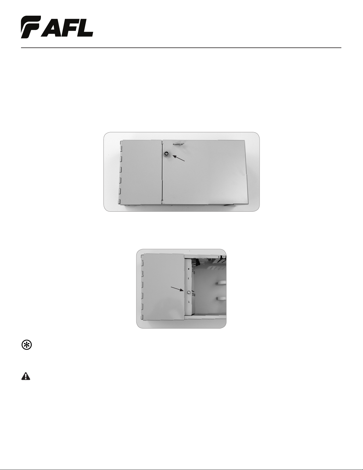
LOCK AND UNLOCK EXTERIOR DOORS
Note: A pad lock, not provided, may be utilized if additional security is desired.
1. Using a standard 216 style tool, or similar, loosen the screw located on the front of the Mini IDC
located on the subscriber door. Do not remove these screws from the cabinet doors. (Figure 2)
Caution: Fiber optic cable is susceptible to damage from excessive bending, pulling or crushing forces.
At every stage of the installation process ensure that the loose buffer tubes, ribbon or Wrapping Tube Cable
(WTC) with SpiderWeb®Ribbon (SWR®) bers are free from unintentional cuts, nicks or bends to avoid
potential ber damage.
1. Mark the cable to have a minimum 46" (116.8 cm) opening.
2. Use local accepted practice to remove the cable sheath.
3. Using wire cutters cut the central strength member back to the sheath opening.
CABLE PREPARATION
Figure 2
Subscriber
Door
Figure 3
Provider
Door
5. Secure the enclosure to the wall by tightening the two lag screws in the top two corners and secure with lag screws in
the bottom corners. Before the lag screws are completely tightened a level may be used to ensure that the enclosure
is in the desired position.
2. With the subscriber door open, using a standard 216 style tool, or similar, loosen the screw located on the provider
side of the cabinet. Do not remove these screws from the cabinet doors. (Figure 3)

5
INSTALLATION INSTRUCTIONS
IDEAA®Mini Interior Distribution Cabinet
© 2016, AFL, all rights reserved. Revision 0, 4.27.17
Specications are subject to change without notice.
1. Determine the appropriate compression tting for the application.
2. Located in the provider side of the cabinet, knock out the appropriate mounting hole to accommodate the
compression tting. (Figure 4)
CABLE INSTALLATION
Figure 4
Note: Note: Knock outs are located on both the top and bottom of the Mini IDC.
3. Install the compression tting, reference the Compression Fitting Installation section of this document. (Figure 5)
4. Using local engineering practices determine which bers will be unused for the input splicing and separate the
bundles from the bers that will be routed to the splice tray.
5. Route the unused buffer tubes or protected SWR ber through the ber management rings located on the back wall
of the Mini IDC. (Figure 6)
Cable Sheath
46” (116.8 cm)
Note: For best practice when working with WTC, it is recommended that accepted local practices be used to
protect the SWR ber before continuing to the cable installation.
Figure 5

6
INSTALLATION INSTRUCTIONS
IDEAA®Mini Interior Distribution Cabinet
© 2016, AFL, all rights reserved. Revision 0, 4.27.17
Specications are subject to change without notice.
COMPRESSION FITTING INSTALLATION
Caution: In order to avoid micro bends or ber damage do not over-tighten the compression tting around
the ber cable.
1. Ensure that the mounting hole is free from burrs and that the cabinet surface is smooth and free of debris.
2. Place the hex portion on the body (not the sealing nut) into the mounting hole.
3. Insert the cable through the tting to the desired position.
Note: For best practice, it is recommended that when working with the 9-port compression tting that the
multi-port grommet be removed from the tting body. Slit each of the application appropriate ports and align
the grommet around the cables. Once all required cables are seated in the grommet, insert both the cables
and grommet back into the tting body.
4. Tighten the sealing nut to hand-tight.
5. Using a wrench hold the body hex stationary while tightening the sealing nut with a second wrench. Tighten until the
cable is held securely in place.
6. Check to ensure that the tting body is still screwed tightly into the panel.
Figure 6
1. To disassemble for cable replacement, loosen the sealing nut.
2. Grip the disconnected cable and pull while turning the cable in the counter-clockwise direction.
DISASSEMBLE COMPRESSION FITTING—CABLE REPLACEMENT
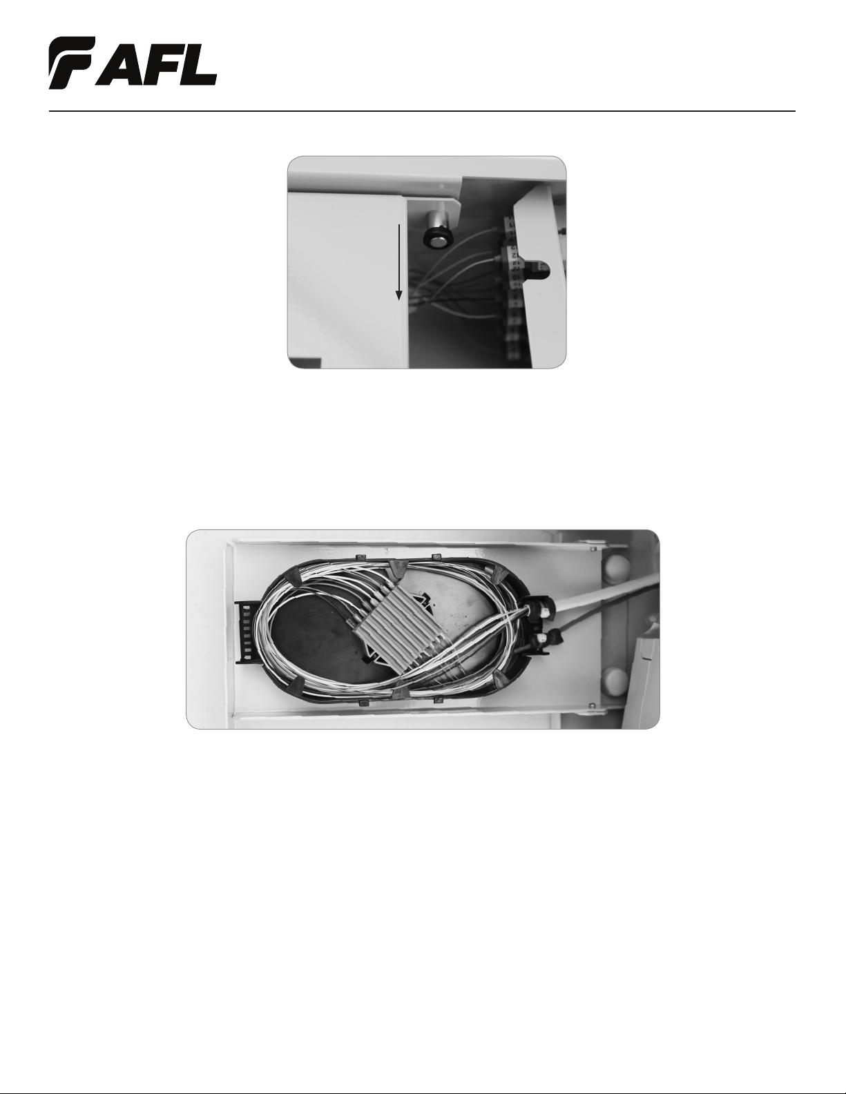
1. Pull down on the pin used to secure the swing down splice tray holder in order to reveal the splice tray. (Figure 7)
SPLICING
7
INSTALLATION INSTRUCTIONS
IDEAA®Mini Interior Distribution Cabinet
© 2016, AFL, all rights reserved. Revision 0, 4.27.17
Specications are subject to change without notice.
2. Prior to splicing, ensure that adequate slack for both the expressed ber and the pigtail ber is stored within
the splice tray. Mark bers for splicing.
3. Clean the individual ber per accepted local practice using an approved ber cleaner.
4. Follow accepted local practice for preparing and splicing express bers and pigtail bers.
5. Once all splicing is complete, route the exposed bers inside the splice tray. (Figure 8)
6. Replace the splice tray cover.
7. Route the expressed ber and the pigtail ber slack through the ber management rings located on the back wall of
the Mini IDC. (Figure 6)
8. Secure the swing down splice tray holder in the upright position ensuring that the pin is engaged.
9. Close the provider door. Using a using a standard 216 style tool, or similar, secure the provider side door.
Figure 7
Figure 8
8
INSTALLATION INSTRUCTIONS
IDEAA®Mini Interior Distribution Cabinet
© 2016, AFL, all rights reserved. Revision 0, 4.27.17
Specications are subject to change without notice.
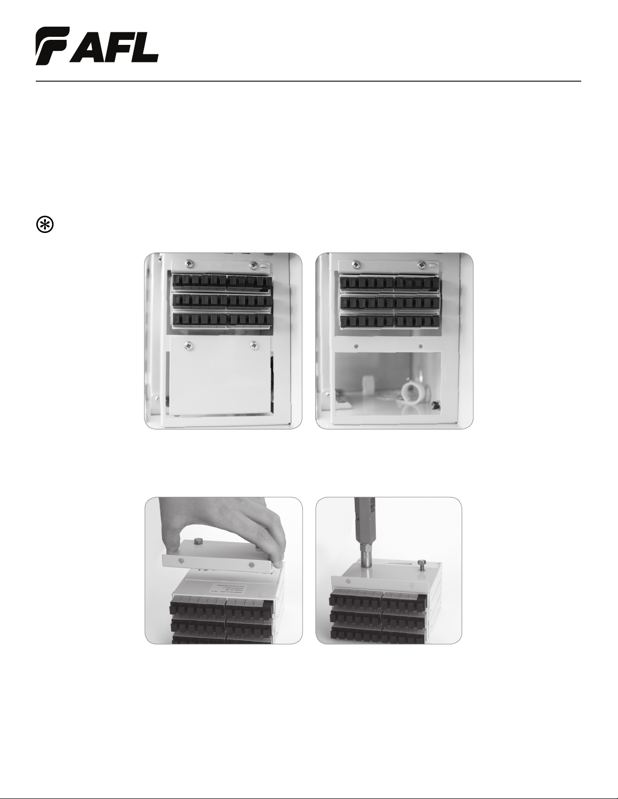
MOUNT IDEAA SPLITTER MODULE
1. Using local engineering practices, determine the location of the IDEAA Splitter Module to be installed within the Mini IDC.
2. Remove the two screws at the top of the cover plate in the desired module location, using a Phillips head
screwdriver. (Figure 10)
Note: These screws will be re-used to mount the IDEAA Splitter Module into the Mini IDC.
IDEAA SPLITTER MODULE INSTALLATION
3. Using the hex-head screws provided with the IDEAA Splitter Module, attach the bottom side of the module to the
removed cover plate. (Figure 11)
Figure 10
Figure 11

9
INSTALLATION INSTRUCTIONS
IDEAA®Mini Interior Distribution Cabinet
© 2016, AFL, all rights reserved. Revision 0, 4.27.17
Specications are subject to change without notice.
Figure 13
4. Re-mount the cover plate with the attached IDEAA module into the desired location, using the screws removed
in Step 2. (Figure 12)
5. Repeat Steps 1 – 4 for each IDEAA Splitter Module that needs to be mounted.
Figure 12
An IDEAA Splitter Module that has been mounted into the IDC is not active until it has been connected to the Input Field.
Caution: When working with ber optics, do not look directly into the end of the ber cable or adapter
port. A power meter may be used to determine if the cable or port is dark. Or use locally accepted ber
optic safety practices.
1. Use local accepted practices to clean the connector end face at both ends of the jumper provided with the Mini IDC.
2. Plug the jumper cable into the black input port on the IDEAA Splitter Module.
Note: When mounted on the cover plate the black input port will be located in the top right corner of the
adapter eld. (Figure 13)
ACTIVATE IDEAA SPLITTER MODULE
Figure 13

10
INSTALLATION INSTRUCTIONS
IDEAA®Mini Interior Distribution Cabinet
© 2016, AFL, all rights reserved. Revision 0, 4.27.17
Specications are subject to change without notice.
3. Using local engineering practices, determine the port to be used on the input panel for activating the IDEAA Splitter
Module. Plug the opposite end of the jumper into the desired port on the input panel. (Figure 14)
Figure 14
4. Use the ber routing rings to route the input jumper to the back of the enclosure. (Figure 15)
Note: For best practice, avoid looping the input jumper slack through the ber routing section of
the Mini IDC.
5. Use local accepted practices to label the input ber connection in the appropriate space on the door label, as applicable.
Note: The lance located above the input port on the IDEAA Module cover plate may be used for additional
labeling. As an alternative, self-adhesive label may be placed on the cover plate.
6. Repeat Steps 1 – 5 for each IDEAA Splitter Module to be activated.
Figure 15
MDU DROP CABLE INSTALLATION
Caution: Fiber optic cable is susceptible to damage from excessive bending, pulling or crushing forces.
At every stage of the installation process ensure that the bers are free from unintentional cuts, nicks or
bends to avoid potential ber damage.
1. Use local accepted practices to remove the cable sheath.

11
INSTALLATION INSTRUCTIONS
IDEAA®Mini Interior Distribution Cabinet
© 2016, AFL, all rights reserved. Revision 0, 4.27.17
Specications are subject to change without notice.
Recommendation: For best practice no more than 22" (60.0 cm) of 900um ber be exposed for the MDU drop
cable installation process. This length will optimize the routing capability within the Mini IDC and prevent
excessive lengths of 900 um ber from collecting within the cabinet.
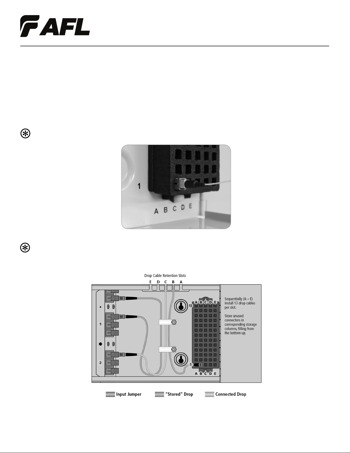
2. Insert the 4.8 mm jacket into the MDU drop retention bracket. (Figure 16)
Figure 16
3. Slide the 4.8 mm drop cable to the backmost position within the drop retention bracket.
Recommendation: For best practice, install the rst MDU drop cable into the backmost position on the right
side of the MDU retention bracket. Continue to ll the rst slot with (13) MDU drop cables before proceeding
to the next cable entry slot. (Figure 17)
Figure 17
4. Ensure that the exposed 900 um ber is long enough to reach the desired IDEAA Splitter Module port.
5. Repeat steps 1 – 4 for all desired MDU drop cables.
12
INSTALLATION INSTRUCTIONS
IDEAA®Mini Interior Distribution Cabinet
© 2016, AFL, all rights reserved. Revision 0, 4.27.17
Specications are subject to change without notice.
6. Install FASTConnect® Mechanical Connector. Reference the installation instructions provided with the
FASTConnect® Mechanical Connector. The document will include the following:
• Fiber Preparation
• Fiber Termination
• Connector Assembly
7. Use local accepted practices to label the MDU drop ber.
8. Insert the connector into the connector storage area of the Mini IDC.
Note: DO NOT remove the dust cap from the connector. (Figure 18)
Figure 18
Recommendation: For best practice, insert the rst connector into the lower left position on the connector
storage area. Continue to ll the rst column with (13) MDU drop cable connectors before proceeding
to the next column. (Figure 19)
Figure 19

13
INSTALLATION INSTRUCTIONS
IDEAA®Mini Interior Distribution Cabinet
© 2016, AFL, all rights reserved. Revision 0, 4.27.17
Specications are subject to change without notice.
1. Using local engineering practices, determine which port on the IDEAA Splitter Module will be used for the
MDU drop connection.
2. Remove the connector from the connector storage area by pulling on the connector body.
Note: DO NOT pull the boot of the connector to release from the connector storage area.
3. Use local accepted practices to clean the distribution ber connector end face.
4. Connect the distribution ber to the appropriate port on the IDEAA Splitter Module. (Figure 21)
IDEAA SPLITTER MODULE INSTALLATION
CONNECT DISTRIBUTION FIBER
9. Use the ber routing rings to route the 900 um ber to the back of the enclosure. (Figure 20)
Figure 20
Note: For best practice, avoid looping the ber slack through the ber routing section of the Mini IDC.
Figure 21
Note: For best practice, avoid looping the ber slack through the ber routing section of the Mini IDC.

14
INSTALLATION INSTRUCTIONS
IDEAA®Mini Interior Distribution Cabinet
© 2016, AFL, all rights reserved. Revision 0, 4.27.17
Specications are subject to change without notice.
1. Using local engineering practices, determine the appropriate distribution ber to be used for a pass through connection.
2. Use local accepted practices to clean the distribution ber connector end face.
3. Connect the distribution ber to the appropriate port on the input eld.
4. Use the ber routing rings to route the remaining distribution ber slack through the ber routing section of the Mini
IDC. Employing a similar technique to that used with the input jumper cable.
5. Repeat Steps 1 – 4 for each addition pass through connection.
PASS THROUGH CONNECTION
5. Use local accepted practices to label the distribution ber connection in the appropriate space on the door label, as applicable.
6. Repeat Steps 1 – 5 for each addition distribution ber needing to be connected.
Table of contents


