Afriso EURO-INDEX KSG Series User manual

Mess-, Regel- und
Überwachungsgeräte
für Haustechnik,
Industrie und Umwel
tschutz
Lindenstraße 20
74363 Güglingen
Telefon
+49 7135-102-0
Service
+49 7135-102-211
Telefax
+49 7135-102-147
www.afriso.de
Vor Gebrauch lesen! / Read manual before use! /
Lire la notice technique avant l'utilisation!
Alle Sicherheitshinweise beachten! / Observe all safety
information! / Respecter toutes les consignes de sécurité !
Für künftige Verwendung aufbewahren! / Keep manual
for future use! / Conserver la notice technique pour toute
utilisation ultérieure !
10.2019.0
854.099.0482
Betriebsanleitung
Instruction Manual / Notice technique
Kesselsicherungsgruppe
Boiler safety group assembly
Groupe de sécurité chaudière
KSG
KSG 3 bar bis/up to/à 50 kW
KSG Maxi 3 bar bis/up to/à 100 kW
Deutsch
English
Français
0036

Sicherheit – Deutsch –
KSG 2
1 Sicherheit
1.1 Bestimmungsgemäße Verwendung
Die Kesselsicherungsgruppe KSG eignet sich ausschließlich zum
Einsatz:
•in geschlossenen Heizungsanlagen nach EN 12828
•für Wärmeerzeuger mit einer Heizleistung bis 50 kW, oder bis
100 kW, je nach Version
Die Kesselsicherungsgruppe KSG eignet sich ausschließlich für fol-
gende Medien:
•Wasser
•Wasser-Glykol-Gemische
Eine andere Verwendung ist nicht bestimmungsgemäß.
1.2 Vorhersehbare Fehlanwendung
Die Kesselsicherungsgruppe KSG darf insbesondere in folgenden
Fällen nicht verwendet werden:
•Betrieb bei abgesperrter Abblaseöffnung
•Betrieb mit verklebenden, ätzenden oder entzündlichen Medien
•Betrieb mit Medien, die die Funktion der Kesselsicherungs-
gruppe KSG beeinträchtigen
•Über- oder Unterschreitung der zulässigen Temperaturen und
Drücke, siehe Tabelle 1, Seite 4
1.3 Sichere Handhabung
Die Kesselsicherungsgruppe KSG entspricht dem Stand der Tech-
nik und den anerkannten sicherheitstechnischen Regeln. Jedes
Produkt wird vor Auslieferung auf Funktion und Sicherheit geprüft.
Die Kesselsicherungsgruppe KSG nur in einwandfreiem Zu-
stand betreiben unter Berücksichtigung der Betriebsanleitung,
den üblichen Vorschriften und Richtlinien sowie den geltenden
Sicherheitsbestimmungen und Unfallverhütungsvorschriften.
1.4 Qualifikation des Personals
Montage, Inbetriebnahme, Betrieb, Wartung, Außerbetriebnahme
und Entsorgung dürfen nur von fachspezifisch qualifiziertem Perso-
nal durchgeführt werden.
1.5 Veränderungen am Produkt
Eigenmächtige Veränderungen am Produkt können zu Fehlfunktio-
nen führen und sind aus Sicherheitsgründen verboten.

– Deutsch – Produktbeschreibung
KSG 3
1.6 Haftungshinweise
Für Schäden und Folgeschäden, die durch Nichtbeachten der tech-
nischen Vorschriften, Anleitungen und Empfehlungen entstehen,
übernimmt der Hersteller keinerlei Haftung oder Gewährleistung.
Der Hersteller und die Vertriebsfirma haften nicht für Kosten oder
Schäden, die dem Benutzer oder Dritten durch den Einsatz dieses
Produkts, vor allem bei unsachgemäßem Gebrauch des Produkts,
Missbrauch oder Störungen des Anschlusses, Störungen des
Produkts oder der angeschlossenen Produkte entstehen. Für nicht
bestimmungsgemäße Verwendung haftet weder der Hersteller noch
die Vertriebsfirma.
Für Druckfehler übernimmt der Hersteller keine Haftung.
2 Produktbeschreibung
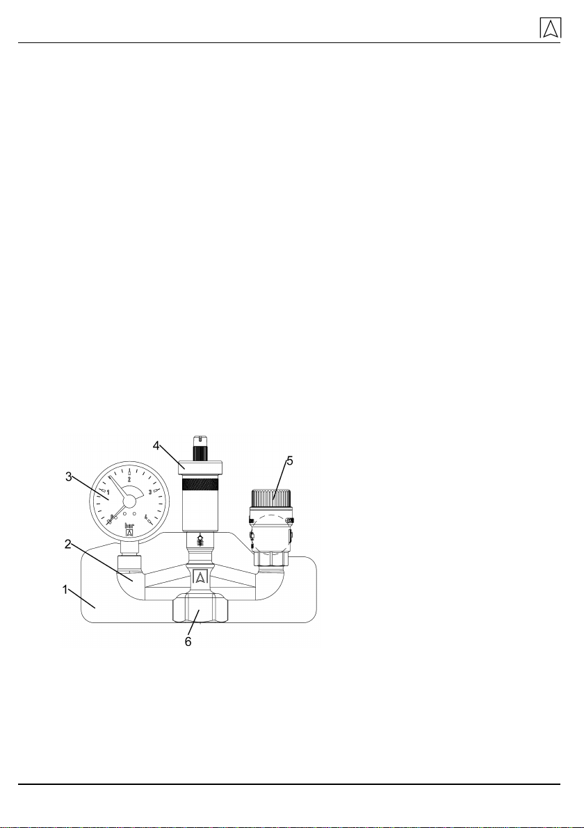
Die Kesselsicherungsgruppe KSG besteht aus einem Membran-
Sicherheitsventil, einem Manometer und einem Schnellentlüfter. Die
Komponenten sind auf einem Armaturenträger montiert. Der Arma-
turenträger befindet sich in einer Isolation.
1 Isolation
2 Armaturenträger mit werkseitig
montierten Armaturen
3 Manometer
4 Schnellentlüfter mit Aquastop
5 Membran-Sicherheitsventil
6 Anschluss an Wärmeerzeuger
Bild 1: Aufbau der Kesselsicherungsgruppe KSG

Technische Daten – Deutsch –
KSG 4
3 Technische Daten
Tabelle 1: Technische Daten
Bild Parameter KSG 3 bar KSG Maxi 3 bar
Abmessungen mit Isolation
(B x H x T) 183 x 144 x 70 mm
Anlagendruck 3 bar
Mediumstemperatur Max. 120 °C
Material Messing
Unterer Anschluss G1 i
Eingang / Durchmesser G1/4-PTFE / 63 mm
Anzeigebereich 0-4 bar
Grüner Bereich 1,5-3 bar
Eingang G3/8 a
Nenndruck 12 bar
Ansprechdruck 3 bar
Eingang x Ausgang G½ i x G¾ i G¾ i x G1 i
Wärmeleistung 50 kW 100 kW
4 Montage/Inbetriebnahme
WARNUNG
Verbrühungen durch heiße Flüssigkeiten in der A
nlage.
Während der Montage, Inbetriebnahme und Wartung der KSG
alle erforderlichen Maßnahmen ergreifen, damit die heißen
Flüssigkeiten keine Gefahr für Personen darstellen.
Während der Beheizung muss Flüssigkeit aus der Abblaselei-
tung des Sicherheitsventils austreten können. KSG unabsper-
rbar montieren. Keine Absperrungen, Schmutzfänger oder
ähnliches einbauen.
KSG so montieren, dass in eingebautem Zustand keine äuße-
ren Kräfte auf die Armaturen wirken.

– Deutsch – Montage/Inbetriebnahme
KSG 5
KSG darf durch Schweiß- und Lötarbeiten an der Anlage nicht
überhitzt werden. KSG erst nach diesen Arbeiten einbauen.
Sicherstellen, dass der Nenndruck der KSG dem Planwert der
Anlage entspricht.
Sicherstellen, dass die Flüssigkeit in der Anlage mit dem Ein-
satzbereich der KSG verträglich ist.
Die Leitungen vor Montage der KSG gut durchspülen. Verun-
reinigungen wie Schweißperlen, Hanf oder Metallspäne ma-
chen das Sicherheitsventil undicht.
4.1 Produkt montieren
Das Sicherheitsventil und das Manometer sind mit einem elasti-
schen Dichtungssystem montiert. Falls erforderlich dürfen sie bis zu
180° verdreht werden, ohne dass der Anschluss undicht wird.
1. KSG so montieren, dass die Armaturen senkrecht stehen.
2. KSG so montieren, dass die Flüssigkeit durch die Abblaseöff-
nung des Sicherheitsventils ungehindert abfließen kann.
3. KSG am höchsten Punkt des Wärmeerzeugers oder in seiner
unmittelbaren Nähe an der Vorlaufleitung montieren. Zwischen
KSG und Wärmeerzeuger darf eine maximal 1 m lange Verbin-
dungsleitung in der Größe des Eingangsquerschnitts installiert
sein.
4. KSG mit den mitgelieferten Isolationshalbschalen (= Wärme-
dämmung) isolieren.
Abblaseleitung des Sicherheitsventils
Die Abblaseöffnung ist durch einen Pfeil auf dem Ventilkörper ge-
kennzeichnet.
WARNUNG
Gesundheitsschäden und Verbrennungsgefahr durch austr
e-
tende, heiße Flüssigkeit an der Abblaseöffnung des Siche
r-
heitsventils.
Die Abblaseleitung so legen, dass weder Personen- noch Sach-
schäden durch die austretende Flüssigkeit verursacht werden.
Die Abblaseleitung mit Gefälle und mindestens in der Größe
des Querschnitts der Abblaseöffnung ausführen.

Montage/Inbetriebnahme – Deutsch –
KSG 6
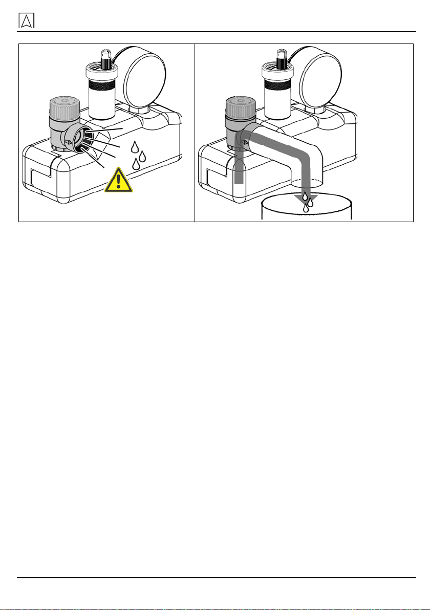
Bild 2: Einbau ohne Abblaseleitung Bild 3: Einbau mit Abblaseleitung
Die Abblaseleitung darf höchstens 2 m lang sein und 2 Bögen
aufweisen. Werden diese Werte überschritten (2 Bögen, 2 m
Leitung), für die Abblaseleitung die nächstgrößere Dimension
wählen mit maximal 3 Bögen und 4 m Leitung.
Die Abblaseleitung muss zugänglich und beobachtbar sein.
Den Ausfluss der Abblaseleitung in einen Entwässerungsablauf
oder Behälter führen, der den Gesamtinhalt der Anlage auf-
nehmen kann. Wenn Gefahr besteht, dass die Abblaseleitung
verstopft wird oder einfrieren kann, eine Unterbrechung der
Abblaseleitung vornehmen, z. B. durch einen Trichter. Die Ab-
laufleitung des Trichters muss den doppelten Querschnitt des
Sicherheitsventil-Eingangs haben.
4.2 Produkt in Betrieb nehmen
1. In der Nähe der Abblaseleitung oder am Sicherheitsventil gut
sichtbar ein Hinweisschild mit folgender Aufschrift anbringen:
“Während der Beheizung muss aus Sicherheitsgründen
Wasser aus der Abblaseleitung austreten. Nicht verschlie-
ßen!”
2. Überprüfen, ob alle Wasseranschlüsse wasserdicht sind.
3. Vor Inbetriebnahme der Anlage das Leitungsnetz durchspülen.

– Deutsch – Betrieb
KSG 7
4.3 Funktionsprüfung Sicherheitsventil
1. Einen geeigneten Behälter zum Auffangen der abgelassenen
Flüssigkeit aus dem Sicherheitsventil bereitstellen.
2. Anwesende Personen vor eventuellen Flüssigkeitsspritzern
schützen.
3. Das Sicherheitsventil kurz durch Drehen der Kappe öffnen.
Flüssigkeit strömt aus.
Nach Loslassen der Kappe darf kein Wasser am Sicherheits-
ventil zurückbleiben.
5 Betrieb Während der Beheizung muss aus Sicherheitsgründen Flüssigkeit
aus der Abblaseleitung des Sicherheitsventils austreten.
Das Sicherheitsventil nicht verschließen.
Die Anlage vor Wiederaufnahme des Betriebes nach dem Aus-
lösen des Sicherheitsventils überprüfen.
6 Wartung
Wann Tätigkeit
Alle 6 Monate
Funktionsprüfung des Sicherheitsventils durchführen, siehe Ka-
pitel 4.3, Seite 7
Sicherstellen, dass sich im Inneren der Anlage keine Ablagerun-
gen bilden, die das Ausfließen der Flüssigkeit aus dem Sicher-
heitsventil hemmen oder die einwandfreie Funktion der Armatu-
ren behindern
7 Störungen
Durch ein integriertes Montageventil kann der Schnellentlüfter bei
unter Druck stehender Anlage ausgetauscht werden.
Reparaturen dürfen ausschließlich von fachspezifisch qualifiziertem
Personal ausgeführt werden.
1. Falls Eingriffe an der unter Druck stehenden Anlage notwendig
sind, Vorsichtsmaßnahmen treffen, um sicher an der unter
Druck stehender Anlagen zu arbeiten.
2. Nach der Reparatur der Anlage, das Sicherheitsventil auf ein-
wandfreie Funktion prüfen, siehe Kapitel 4.3, Seite 7.
Kundenzufriedenheit – Deutsch –
KSG 8
Tabelle 2: Störungen
Problem Mögliche Ursache Fehlerbehebung
Zeiger des Manometers
unterhalb des grünen
Bereichs
Anlagendruck zu
gering
Flüssigkeit in die Anlage füllen
bis Zeiger des Manometers
wieder im grünen Bereich ist
Zeiger des Manometers
kurz nach Befüllen der
Anlage wieder unterhalb
des grünen Bereichs
Undichtheit in der
Anlage
Anlage auf Undichtheiten
überprüfen
8 Kundenzufriedenheit
Für uns hat die Zufriedenheit des Kunden oberste Priorität. Wenn
Sie Fragen, Vorschläge oder Schwierigkeiten mit Ihrem Produkt ha-
ben, wenden Sie sich bitte an uns.
9 Adressen
Die Adressen unserer Niederlassungen weltweit finden Sie im Inter-
net unter www.afriso.de.
10 Anhang
10.1 EU-Konformitätserklärung
– English – Safety
KSG 9
1 Safety
1.1 Intended use
The boiler safety group assembly KSG may only be used for the fol-
lowing applications:
•In sealed heating systems as per EN 12828
•For heat generators with a heating capacity of up to 50 kW or up
to 100 kW, depending on the version
The boiler safety group assembly KSG may only be used for the fol-
lowing media:
•Water
•Water/glycol mixtures
Any use other than the application explicitly permitted in this instruc-
tion manual is not permitted.
1.2 Predictable incorrect application
The boiler safety group assembly KSG must never be used in the fol-
lowing cases:
•Operation when the discharge opening is shut off
•Use with adherent, corrosive or flammable fluids
•Operation with media that have an adverse effect on the proper
operation of the boiler safety group KSG
•Temperatures in excess of or below the permissible tempera-
tures and pressures, see table 1, page 11
1.3 Safe handling
The boiler safety group assembly KSG represents state-of-the-art
technology and is made according to the pertinent safety regulations.
Each device is subjected to a function and safety test prior to ship-
ping.
Operate the boiler safety group assembly KSG only when it is in
perfect condition. Always observe the operating instructions, all
pertinent local and national directives and guidelines as well as
the applicable safety regulations and directives concerning the
prevention of accidents.
1.4 Staff qualification
The product may only be mounted, commissioned, operated, main-
tained, decommissioned and disposed of by qualified, specially
trained staff.
Product description – English –
KSG 10
1.5 Modifications to the product
Changes or modifications made to the product by unauthorised per-
sons may lead to malfunctions and are prohibited for safety reasons.
1.6 Liability information
The manufacturer shall not be liable in any form whatsoever for
direct or consequential damage resulting from failure to observe the
technical instructions, guidelines and recommendations.
The manufacturer or the sales company shall not be liable for costs
or damages incurred by the user or by third parties in the usage or
application of this device, in particular in case of improper use of the
device, misuse or malfunction of the connection, malfunction of the
device or of connected devices. The manufacturer or the sales
company shall not be liable for damage whatsoever resulting from
any use other than the use explicitly permitted in this instruction
manual.
The manufacturer shall not be liable for misprints.
2 Product description
The boiler safety group assembly KSG consists of a diaphragm safe-
ty valve, a pressure gauge and a quick air vent. The components are
mounted on a carrier. The carrier is contained in an insulation piece.
1 Insulation piece
2 Carrier with factory-installed
components
3 Pressure gauge
4 Quick air vent with aqua stop
5 Diaphragm safety valve
6 Connection to heat generator
Fig. 1: Components of the boiler safety group assembly

– English – Technical specifications
KSG 11
3 Technical specifications
Table 1: Technical specifications
Fig. Parameters KSG 3 bar KSG Maxi 3 bar
Dimensions with insulation
(W x H x D) 183 x 144 x 70 mm
System pressure 3 bar
Temperature of medium Max. 120 °C
Material Brass
Bottom connection G1
Inlet / Diameter G1/4-PTFE / 63 mm
Range 0-4 bar
Green area 1,5-3 bar
Inlet G3/8
Nominal pressure 12 bar
Response pressure 3 bar
Inlet x outlet G½ x G¾ G¾ x G1
Heat capacity 50 kW 100 kW
4 Mounting/commissioning
WARNING
Scald
ing due to hot liquids in the system.
Take all necessary measures during mounting, commissioning
and maintenance of KSG to ensure that hot liquids do not pose
any hazard to persons.
During heating up, liquid must be able to escape via the dis-
charge line of the safety valve.
Install KSG in such a way that it cannot be shut off.
Do not install shut-off valves, filters or similar equipment.
Install KSG in such a way that no external forces can act on the
components when it is installed.
Mounting/commissioning – English –
KSG 12
Do not overheat KSG by welding or soldering work performed
on the system. Install KSG after completion of such welding or
soldering work.
Verify that the nominal pressure of KSG corresponds to the
planned value of the system.
Verify that the liquid in the system and the application area of
KSG are compatible.
Thoroughly flush the pipes prior to installing KSG. Impurities
such as weld beads, hemp or metal chips cause leaks of the
safety valve.
4.1 Mounting the device
The safety valve and the pressure gauge are mounted with an elastic
sealing system. If necessary, they can be rotated by up to 180° with-
out the connection becoming leaky.
1. Mount KSG in such a way that the components are vertical.
2. Mount KSG in such a way that the liquid can escape via the dis-
charge opening of the safety valve without obstructions.
3. Mount KSG at the highest point of the heat generator or in its
immediate vicinity at the flow line. A connection line with a max-
imum length of 1 m and the size of the inlet cross section may
be installed between KSG and the heat generator.
4. Mount KSG with the insulation shells supplied with the unit
(= heat insulation).
Discharge line of the safety valve
The discharge opening is designated by an arrow on the valve body.
WARNING
Injuries and hazard of scal
ding due to hot liquid escaping via
the discharge opening of the safety valve.
Install the discharge line in such a way as to avoid any damage
or injuries due to escaping liquid.
The discharge line must have a gradient; its cross section must
have at least the same cross section as that of the discharge
opening.
– English – Mounting/commissioning
KSG 13
Fig. 2: Installation without discharge
line Fig. 3: Installation with discharge line
The length of the discharge line must not exceed 2 m; the max-
imum number of elbows is 2. If these values (2 elbows, 2 m line
length) are exceeded, the diameter next in size must be used
for the discharge line with a maximum of 3 elbows and a maxi-
mum line length of 4 m.
The discharge line must be accessible and observable.
Drain the liquid discharged via the discharge line into a drain
outlet or a container that can hold the total capacity of the sys-
tem. If the discharge line is subject to potential clogging or
freezing, interrupt the discharge line, e.g. by means of a funnel.
The drain line of the funnel must have twice the cross section of
the inlet of the safety valve.
4.2 Commissioning the device
1. Affix a label in the vicinity of the discharge line or to the safety
valve with the following text:
"For safety reasons, water must escape via the discharge
line during heating. Do not shut off!"
2. Verify that all water connections are water-tight.
3. Flush the entire pipe system prior to commissioning the system.

Operation – English –
KSG 14
4.3 Function test safety valve
1. Provide a suitable container to collect the liquid discharged via
the safety valve.
2. Protect persons against splashes of the liquid.
3. Briefly open the safety valve by turning the cap.
Liquid escapes.
After releasing the cap, no water may remain at the safety valve.
5 Operation
For safety reasons, liquid must escape via the discharge line of the
safety valve during heating.
Do not shut off the safety valve.
If the safety valve has responded, check the system prior to re-
suming operation.
6 Maintenance
When Activity
Every 6 months
Perform a function test of the safety valve, see chapter 4.3,
page 14
Verify that no accumulations can form in the system which can
interfere with the discharge of the liquid from the safety valve
or with the proper operation of the components
7 Troubleshooting
Due to the integrated mounting valve, the quick air vent can be re-
placed while the system is under pressure.
Repairs may only be performed by specially trained, qualified staff.
1. If you need to perform work on the pressurised system, take all
necessary precautions to ensure that such work on the pressur-
ised system can be performed safely.
2. After repairs of the system, check the safety valve for proper
operation, see chapter 4.3, page 14.

– English – Customer satisfaction
KSG 15
Table 2: Troubleshooting
Problem Possible reason Repair
Pointer of pressure
gauge below green
range
System pressure too
low
Fill liquid into the system until
the pointer of the pressure
gauge is in the green range
Pointer of the pressure
gauge again below green
range after filling of the
system
Leak in system
Check system for leaks
8 Customer satisfaction
Customer satisfaction is our prime objective. Please get in touch with
us if you have any questions, suggestions or problems concerning
your product.
9 Addresses
The addresses of our worldwide representations and offices can be
found on the Internet at www.afriso.de.
10 Appendix
10.1 Declaration of Conformity
See chapter 10.1, page 8.

– Français –
KSG 16
1 Sécurité
1.1 Utilisation conforme
Le groupe de sécurité chaudière KSG est destiné exclusivement à
l'utilisation :
•dans les installations de chauffage fermées suivant la norme
EN 12828
•sur les générateurs de chaleur dont la puissance maximale est
de 50 kW ou de 100 kW selon la version.
Le groupe de sécurité chaudière KSG est destiné exclusivement à
l'utilisation avec les liquides ci-dessous :
•eau
•mélanges eau-glycol
Toute autre utilisation n'est pas conforme.
1.2 Utilisation non conforme prévisible
Le groupe de sécurité chaudière KSG ne doit, en particulier, pas être
utilisé dans les cas suivants :
•fonctionnement quand l’orifice de purge est bloqué
•fonctionnement avec des fluides collants, corrosifs ou inflam-
mables
•fonctionnement avec des fluides susceptibles de nuire au fonc-
tionnement du groupe de sécurité chaudière KSG
•dépassement des limites inférieures ou supérieures prévues de
température et de pression, voir tableau 1, page 18
1.3 Sécurité
Le groupe de sécurité chaudière KSG est conforme à l'état de la
technique et aux règlements de sécurité reconnus. Le bon fonction-
nement et la sécurité de chaque appareil sont vérifiés avant la livrai-
son.
Le groupe de sécurité chaudière KSG ne doit être utilisé que s'il
est en parfait état et conformément aux prescriptions de sa no-
tice technique. L'utilisation doit également respecter toutes les
normes et directives relatives à la sécurité et à la prévention des
accidents.
1.4 Qualification du personnel
Le montage, la mise en service, la maintenance, la mise hors service
et l’élimination ne doivent être effectués que par de personnel
spécialisé et qualifié.

– Français – Description du produit
KSG 17
1.5 Modification du produit
Toute modification du produit risque de générer des dysfonctionne-
ments et est, par conséquent, interdite pour des raisons de sécurité.
1.6 Responsabilité
La responsabilité du fabricant ou la garantie ne pourra être engagée
pour des dommages ou dommages consécutifs résultant d’une
inobservation des dispositions techniques, conseils ou directives.
Le fabricant et le distributeur ne sont pas responsables des coûts ou
dommages subis par l’utilisateur ou un tiers du fait de l'utilisation de
l'appareil, en particulier du fait d'une utilisation inadéquate, du fait
d'une utilisation erronée ou du fait des défauts de raccordement ou
de l'appareil ou des appareils raccordés. Le fabricant ou le
distributeur déclinent toute responsabilité en cas d’utilisation non
conforme.
Le fabricant décline toute responsabilité pour les erreurs
d'impression.
2 Description du produit
Le groupe de sécurité chaudière KSG est composé d'une soupape
de sécurité à membrane, d'un manomètre et d'un purgeur d'air rapi-
de. Les composants sont montés sur un support. Le support se trou-
ve dans une isolation thermique.
1 Isolation thermique
2 Support et composants pré-
montés en usine
3 Manomètre
4 Purgeur d’air rapide avec aq-
uastop
5 Soupape de sécurité à mem-
brane
6 Raccordement au générateur
de chaleur
Figure 1: Composants

– Français –
KSG 18
3 Caractéristiques techniques
Tableau 1: Caractéristiques techniques
Fig. Paramètre KSG 3 bar KSG Maxi 3 bar
Dimensions avec isolation
(larg. x haut. x prof.) 183 x 144 x 70 mm
Pression de l’installation 3 bar
Température du fluide Max. 120 °C
Matériau Laiton
Raccordement inférieur G1
Entrée / Diamètre G1/4-PTFE / 63 mm
Plage d’affichage 0-4 bar
Plage verte 1,5-3 bar
Entrée G3/8
Pression nominale 12 bar
Pression de réponse 3 bar
Entrée x sortie G½ x G¾ G¾ x G1
Puissance calorifique 50 kW 100 kW
4 Montage et mise en service
AVERTISSE-
MENT
Échaudures causées par des liquides brûlants dans
l‘installation.
Au cours du montage, de la mise en service et de l’entretien de
KSG prendre toutes les mesures nécessaires afin que les liqui-
des brûlants ne mettent pas les personnes en danger.
Au cours du chauffage, il faut que le liquide puisse s’échapper
par la conduite de purge de la soupape de sécurité.
Monter KSG de sorte qu’il ne soit pas verrouillable.
Ne monter ni robinets d‘arrêt ni filtres ni dispositifs similaires.

– Français – Montage et mise en service
KSG 19
Monter KSG de sorte qu’aucune force extérieure n’agisse sur
les composants montés.
KSG ne doit pas être soumis à une surchauffe causée par des
opérations de soudage et de brasage. Ne pas monter KSG
avant que ces opérations soient terminées.
S’assurer que la pression nominale de KSG corresponde aux
paramètres prévus pour l’installation.
S’assurer que le liquide dans l’installation soit compatible avec
le domaine d’application de KSG.
Purger soigneusement les conduites avant le montage de KSG.
Les impuretés (perles de soudure, chanvre ou copeaux de
métal, par ex.) causeraient des fuites de la soupape de sécurité.
4.1 Montage de l’appareil
La soupape de sécurité et le manomètre sont montés avec un sys-
tème d’étanchéification élastique. Si nécessaire, il est possible
d’effectuer une rotation allant jusqu’à 180° sans qu’il y ait de fuite au
raccordement.
1. Monter KSG de sorte que les composants se trouvent à la verti-
cale.
2. Monter KSG de sorte que le liquide puisse s’écouler facilement
par l’orifice de purge de la soupape de sécurité.
3. Monter KSG au point le plus élevé du générateur de chaleur ou
à proximité immédiate de celui-ci sur la conduite d’arrivée. Entre
KSG et le générateur de chaleur, la conduite de raccordement
installée doit avoir une longueur maximale d’1 mètre et une sec-
tion égal à la section d’entrée.
4. Isoler KSG avec l’isolation thermique jointe à la livraison.
Conduite de purge de la soupape de sécurité
L’orifice de purge est marqué d’une flèche sur le corps de la
soupape.
AVERTISSE-
MENT
Dommages corporels et risques d’échaudures causés par
l’écoulement de liquide brûlant par l’
orifice de purge de la
soupape de sécurité.
Poser la conduite de purge de sorte que les fuites de liquides ne
causent pas de dommages corporels ou matériels.
Poser la conduite de purge avec une déclivité, sa section étant
au moins égal à celle-ci de l’orifice de purge.

– Français –
KSG 20
Figure 2 : Montage sans conduite de
purge Figure 3 : Montage avec conduite de purge
La conduite de purge ne doit pas dépasser 2 mètres et ne pas
comporter plus de 2 coudes. En cas de dépassement de ces
valeurs (2 coudes, conduite de 2 mètres), il faut choisir la di-
mension supérieure pour la conduite de purge sans prévoir plus
de 3 coudes ou une conduite supérieure à 4 mètres.
La conduite de purge doit être accessible et elle doit pouvoir
être observée.
Amener l’écoulement de la conduite de purge dans une con-
duite de drainage ou un récipient capable de contenir le contenu
total de l’installation. Si la conduite de purge risque de se bou-
cher ou de geler, prévoir une interruption de la conduite de
purge sous forme de trémie, par exemple. La section de la con-
duite d’écoulement de la trémie doit être double de celle-ci de
l’entrée de la soupape de sécurité.
4.2 Mise en service
1. À proximité de la conduite de purge ou sur la soupape de sécu-
rité apposer un panneau de signalisation bien visible portant
l’inscription suivante :
" Pendant le chauffage il faut que l’eau puisse s’écouler de
la conduite de purge pour des raisons de sécurité. Ne pas
obturer ! "
2. Vérifier que tous les raccordements d’eau sont étanches.
3. Avant la mise en service de l’installation purger le réseau de
conduites.
This manual suits for next models
2
Table of contents
Languages:


