Afriso EURO-INDEX RG 210 User manual
Mess-, Regel- und
Überwachungsgeräte
für Haustechnik,
Industrie und Umweltschutz
Lindenstraße 20
DE-74363 Güglingen
Telefon: +49(0)7135-102-0
Service: +49(0)7135-102-211
Telefax: +49(0)7135-102-14
7
E-Mail: info@afriso.de
Internet: www.afriso.de
Read manual before use!
Observe all safety information!
Keep manual for future use!
01.2009 0
854.001.0149
Instruction Manual
Level Controller
RG 210
# 53206

2RG 210
Contents
1 This instruction manual ............................................................................................3
1.1 Structure of warning .....................................................................................3
1.2 Explanation of symbols and typeface...........................................................3
2 Safety.......................................................................................................................4
2.1 Intended use .................................................................................................4
2.2 Predictable incorrect application ..................................................................4
2.3 Safe handling................................................................................................5
2.4 Staff qualification ..........................................................................................5
2.5 Modifications to the product..........................................................................5
2.6 Use of spare parts and accessories .............................................................6
2.7 Liability information.......................................................................................6
3 Product description ..................................................................................................6
3.1 Operating modes ..........................................................................................7
3.2 Application examples....................................................................................9
4 Specifications.........................................................................................................10
4.1 Approvals, tests and conformities ..............................................................12
5 Transportation and storage....................................................................................12
6 Installation and commissioning..............................................................................13
6.1 Installing the device ....................................................................................13
6.2 Electrical connection...................................................................................14
6.3 Selecting the operating mode.....................................................................16
6.4 Commissioning the device..........................................................................16
6.5 Function test ...............................................................................................17
7 Operation ...............................................................................................................17
8 Maintenance ..........................................................................................................17
8.1 Maintenance intervals.................................................................................17
8.2 Maintenance activities ................................................................................18
9 Troubleshooting .....................................................................................................18
10 Shutting down and disposal...................................................................................19
11 Spare parts and accessories .................................................................................19
12 Warranty ................................................................................................................20
13 Copyright................................................................................................................20
14 Customer satisfaction ............................................................................................20
15 Addresses ..............................................................................................................20

This instruction manual
RG 210 3
1 This instruction manual
This instruction manual is part of the product.
X Read this manual before using the product.
X Keep this manual during the entire service life of the product
and always have it readily available for reference.
X Always hand this manual over to future owners or users of the
product.
1.1 Structure of warning
WARNING TERM
Type and source of the danger is shown here.
X Precautions to take in order to avoid the danger are shown
here.
There are three different levels of warnings:
Warning term Meaning
DANGER Immediately imminent danger!
Failure to observe the information will result in
death or serious injuries.
WARNING Possibly imminent danger!
Failure to observe the information may result in
death or serious injuries.
CAUTION Dangerous situation!
Failure to observe the information may result in
minor or serious injuries as well as damage to
property.
1.2 Explanation of symbols and typeface
Symbol Meaning
; Prerequisite for an activity
X Activity consisting of a single step
1. Activity consisting of several steps
ª Result of an activity
• Bulleted list
Text Indication on a display
Highlighting Highlighting

Safety
4RG 210
2 Safety
2.1 Intended use
The RG 210 level controller may only be used as a level switch, as
level control for filling or as level control for emptying for liquids. The
RG 210 level controller detects minimum or maximum levels and
switches pumps or valves to control levels of liquids.
The RG 210 level controller consists of a control unit and one PTC
thermistor probe (level switch) or two PTC thermistor probes (level
control for filling and emptying). The control unit may only be used
with PTC thermistor probes type 937 and type 150.
The RG 210 level controller may only be used for the following
liquids:
With the type 937 PTC thermistor probe only for:
• Fuel oil EL, L or M
With the type 150 PTC thermistor probe only for:
• Water
• Fuel oil EL, L or M
• Diesel fuel or low-viscosity lubricants group AIII and danger
class AIII
• Motor oils, gearbox oils and hydraulic oils
• Vegetable oils and transformer oils
• Antifreeze agents
• Oil-water mixtures, emulsion
and comparable liquids (not AI, AII !) with equivalent heat conductiv-
ity if these liquids do not attack the following wetted parts:
• PTC thermistor probe: stainless steel
• Plastic: PA6 (Furkamid B SK 1)
• Sealing material: 3M Scotch Cast No 815 perm. elast. 2 comp.
• Cable Oilflex 100: resistant to acids, lye and oils and not agglu-
tinating or coking
Any use other than the use explicitly stated in this instruction manual
is not permitted.
2.2 Predictable incorrect application
The RG 210 level controller must never be used in the following:
• Use as an overfill alarm system according to TRbF

Safety
RG 210 5
• Hazardous areas (ex)
If the device is operated in hazardous areas, sparks may cause
deflagrations, fires or explosions
2.3 Safe handling
This product represents state-of-the-art technology and is manufac-
tured in accordance with the pertinent safety regulations. Each unit is
subjected to a function and safety test prior to despatch.
X Operate the product only when it is in perfect condition. Always
observe the instruction manual, all pertinent local and national
directives and guidelines as well as health and safety regula-
tions and directives regarding the prevention of accidents.
WARNING Severe burns or death due to mains voltage in the control unit
(AC 230 V, 50 Hz).
X Do not expose the control unit to water.
X Interrupt the mains voltage supply before opening the control
unit or before performing maintenance and cleaning work and
make sure it cannot be switched on by accident.
X Do not tamper with the control unit in any way whatsoever.
WARNING Risk of burns and explosions due to hot probe tip (probe tip can
reach temperatures of up to 100 °C).
X Never touch the probe tip.
X The probe and the control unit must not be operated in hazard-
ous areas.
2.4 Staff qualification
The product may only be installed, commissioned, operated, main-
tained, shut down and disposed of by qualified, specially trained per-
sonnel.
Electrical work may only be carried out by qualified electricians in
accordance with local and national regulations.
2.5 Modifications to the product
Changes or modifications made to the product by unauthorised per-
sons may lead to malfunctions and are prohibited for safety reasons.

Product description
6RG 210
2.6 Use of spare parts and accessories
Use of unsuitable spare parts and accessories may cause damage
to the product.
X Use only the manufacturer’s genuine spare parts and accesso-
ries (refer to chapter 0, page 19).
2.7 Liability information
The manufacturer shall not be liable for direct or consequential dam-
age resulting from failure to observe the technical instructions, guide-
lines and recommendations.
The manufacturer and the sales company shall not be liable for costs
or damages incurred by the user or by third parties in the usage or
application of this device, in particular in case of improper use of the
device, misuse or malfunction of the connection, malfunction of the
device or of connected devices. The manufacturer or the sales com-
pany shall not be liable for damages resulting from any use other
than the use explicitly stated in this instruction manual.
The manufacturer shall not be liable for misprints.
3 Product description
Control unit
The control unit contains the following elements in an impact-resis-
tant plastic housing: Display elements and controls as well as all
electronic components for signal processing and conversion of the
probe signal into a digital output signal. The output signal is available
as a voltage-free relay contact (1 changeover contact).
RG 210 can be operated with the type 937 and type 150 PTC ther-
mistor probes. The PTC thermistor probes are not included with the
RG 210.
1Yellow LED for
probes
2Green LED for
release
3Base
4Upper part of
housing
Fig. 1: Control unit
Product description
RG 210 7
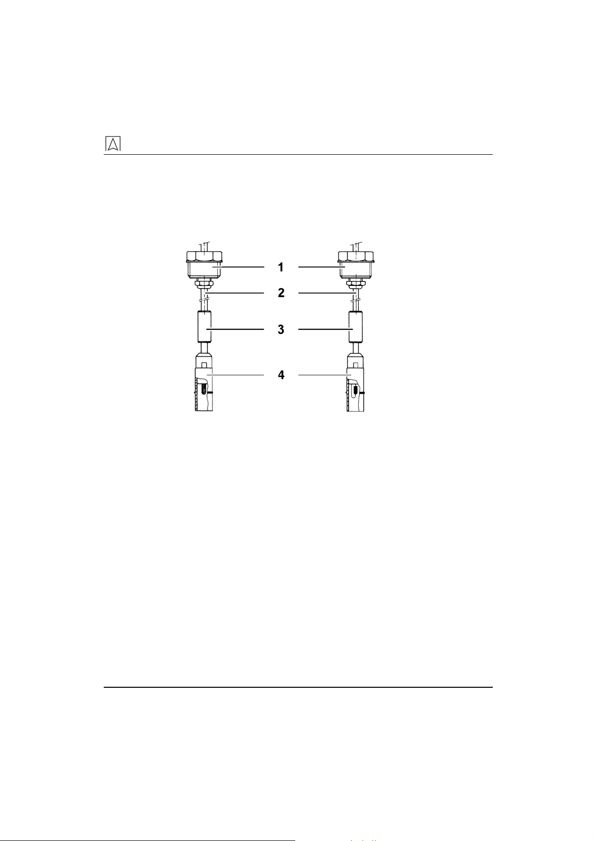
Probe
The control unit and the PTC thermistor probe are connected by
means of a signal cable. The tip of the probe is equipped with a PTC
thermistor. During operation, the PTC thermistor is heated and can
distinguish between gaseous and liquid media due to the different
heat dissipation.
1Plastic screw
connector
2Probe cable
3Brass weight
4Protective sleeve
for PTC thermis-
tor
Fig. 2: Probe type 150 Fig. 3: Probe type 937
3.1 Operating modes
When the mains voltage is switched on, the connected PTC thermis-
tor heats up. Three different operating modes must be distinguished.
The various operating modes are set by means of a selector on the
printed circuit board.
Operating mode “Probe 1”: level switch
Only the signal received from probe 1 is processed. A second probe
may be connected, but it will not be considered.
If the PTC thermistor is exposed to air (i. e. not submerged in liquid)
once probe 1 is fully heated up, the yellow LED "Probe 1" goes out,
the green LED "Release" lights up and the output relay is energised.
If the PTC thermistor of probe 1 is submerged in liquid or if the heat-
up process of probe 1 is not yet finished or if probe 1 is not con-
nected or short-circuited, the yellow LED "Probe 1" lights up, the
green LED "Release" goes out and the output relay is de-energised.
Operating mode "Filling": level control for filling
Both PTC thermistor probes "Probe 1" and "Probe 2" must be con-
nected. The following applies to both probes in this operating mode:
If the PTC thermistor is exposed to air (not submerged in a liquid)

Product description
8RG 210
once the heat-up process of one probe is completed, the yellow LED
of the corresponding probe goes out. If the PTC thermistor of a
probe is submerged in liquid or if the heat-up process of the probe is
not yet completed or the probe is not connected or short-circuited,
the yellow LED of the corresponding probe lights up.
Logical connection between the two probe signals and an output sig-
nal: If both probes are no longer submerged in the liquid, the green
LED "Release" lights up and the output relay is energised. If both
probes are submerged in the liquid, the green LED "Release" goes
out and the output relay is de-energised.
Operating mode "Emptying": level control for emptying
Both PTC thermistor probes "Probe 1" and "Probe 2" must be con-
nected. The following applies to both probes in this operating mode:
If the PTC thermistor is submerged in the liquid, the yellow LED of
the corresponding probe goes out. If the PTC thermistor of a probe is
exposed to air or if the probe is not connected or short-circuited, the
yellow LED of the corresponding probe lights up.
Logical connection between the two probe signals and an output sig-
nal: If both probes are submerged in the liquid, the green LED "Re-
lease" lights up and the output relay is energised. If both probes are
no longer submerged in the liquid, the green LED "Release" goes out
and the output relay is de-energised.
General information
In case of a power failure, the relay is always de-energised. When
power is available again, both probes must either be exposed to air
or submerged in the liquid before release is possible. A start delay of
approx. 15 seconds prevents a release before the heat-up phase is
completed.
RG 210 can be operated with or without additional external devices.
The following types of additional devices can be used: visual and
audible alarm units, telecommunication devices, building control sys-
tems, building automation systems, pumps, valves, etc.

Product description
RG 210 9
3.2 Application examples
1Pump stop
2RG 210
3Probe 1
4Maximum level
Fig. 4: Application as level switch
1Pump On/Off
2RG 210
3Probe 1
4Probe 2
5Maximum level
6Minimum level
Fig. 5: Application as level control for filling/emptying
1RG 210
2AFRISO event
reporting system
3Internet
4Email
5Mobile phone
6Fax
7Phone
Fig. 6: Remote reporting with AFRISO event reporting system

Specifications
10 RG 210
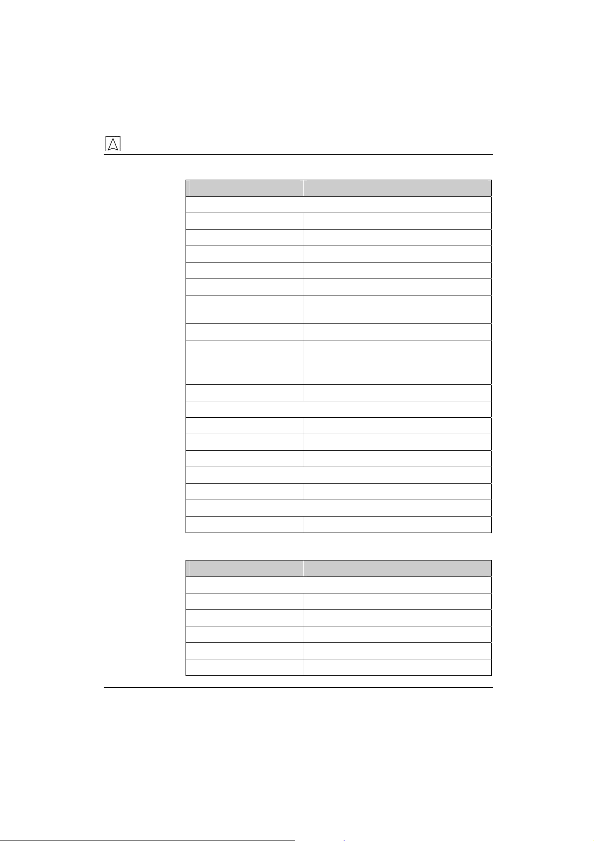
4 Specifications
Table 1: Specifications control unit
Parameter Value
General specifications
Dimensions (W x H x D) 53 x 113 x 108 mm
Weight 0.55 kg
Response delay None
Indication of probe signals 2 yellow LEDs
Indication of output signal 1 green LED
Outputs 1 output relay (changeover con-
tact)
Connections For 2 PTC thermistor probes
Operating temperature range
Ambient -10 °C to +55 °C
Storage -10 °C to +60 °C
Supply
Supply voltage AC 230 V ± 10 %, 50 Hz
Rated power Max. 12 VA
Mains fuse M 100 mA (5 x 20 mm)
Breaking capacity output relay Max. 250 V, 2 A, resistive load
Electrical safety
Electrical safety EN 61010
Protection class II DIN 57700
Protection IP 30 EN 60529
Electromagnetic compatibility (EMC)
Noise suppression EN 61000-6-3
Noise immunity EN 61000-6-2
Specifications
RG 210 11
Table 2: Specifications probe type 150 (not included)
Parameter Value
General specifications
Dimensions (Ø x L) 14 x 57 mm
Weight 130 g
Screw connection Plastic, R1“, 1 bar
Weight Brass, Ø x L = 12 x 40 mm
Probe housing Plastic, Ø = 14 mm
Probe element Stainless steel-encapsulated PTC ther-
mistor
Resistance Refer to chapter 2.1, page 4
Connection cable
Standard length
Maximum length
Oilflex 2 x 0.5 mm²
3 m
50 m (screened)
Heat-up time Approx. 8 s
Operating temperature range
Ambient -25 °C to +75 °C
Medium -25 °C to +50 °C
Storage -25 °C to +75 °C
Supply
Probe voltage Max. DC 12 V
Electrical safety
Protection IP 68 EN 60529
Table 3: Specifications probe type 937 (not included)
Parameter Value
General specifications
Dimensions (Ø x L) 14 x 57 mm
Weight 130 g
Screw connection Plastic, R1“, 1 bar
Weight Brass, Ø x L = 12 x 40 mm
Probe housing Plastic, Ø = 14 mm

Transportation and storage
12 RG 210
Parameter Value
Probe element Wired PTC thermistor
Resistance Refer to chapter 2.1, page 4
Connection cable
Standard length
Maximum length
Oilflex 2 x 0.5 mm²
3 m
50 m (screened)
Heat-up time Approx. 8 s
Operating temperature range
Ambient -25 °C to +75 °C
Medium -25 °C to +50 °C
Storage -25 °C to +75 °C
Supply
Probe voltage Max. DC 12 V
Electrical safety
Protection IP 68 EN 60529
4.1 Approvals, tests and conformities
RG 210 conforms to the EMC Directive (89/336/EEC and
92/31/EEC) and the Low Voltage Directive (73/23/EEC and
93/68/EEC).
5 Transportation and storage
CAUTION Damage to the device due to improper transportation.
X Do not throw or drop the device.
X Protect the device from wetness, humidity, dirt and dust.
CAUTION Damage to the device due to improper storage.
X Protect the device against shock when storing it.
X Store device in a clean and dry environment.
X Store device only within its permissible temperature range.
X Protect the device from wetness, humidity, dirt and dust.

Installation and commissioning
RG 210 13
6 Installation and commissioning
;
The control unit and the probes must not be installed in hazard-
ous areas.
;
The control unit must be mounted to an even, rigid and dry wall
at eye level.
;
The control unit must be accessible and easy to oversee at all
times.
;
The control unit must not be reached by water or splash water.
;
The control unit must not be installed in damp rooms.
;
The maximum ambient temperature at the control unit must not
be exceeded, refer to table 1, page 10.
;
In the case of outdoor installation, the control unit must be pro-
tected from direct atmospheric influences.
;
A properly operating system requires the tank to be equipped
with an overflow pipe or an overfill alarm system according to
TRbF.
;
When the switch point is set, observe that the PTC thermistor
requires up to 15 seconds to heat up depending on the ambient
temperature.
The heat-up time of the PTC thermistor after loss of contact with a
liquid is approx. 30 seconds, depending on the liquid.
6.1 Installing the device
Control unit
1. Loosen the two housing screws at the front of the control unit
and remove the grey upper part of the housing from the black
base.
2. Mount the black base to the wall using two fastening screws
(DIN 96-4 x 35, though the mounting holes).
3. Connect the unit electrically as described in chapter 6.2,
page 14.
4. Select the operating mode as described in chapter 6.3, page 15.
5. Refit the grey upper part of the housing to the black base and
fasten it with the two housing screws.
Make sure the contact bar of the printed circuit board does not
damage the contact springs of the black base.
Installation and commissioning
14 RG 210
Probe
;
Splashes of the liquid may cause a premature response of the
PTC thermistor. Select an appropriate installation location.
X Fasten the PTC thermistor probe(s) at the desired tank
height(s).
X G1" threaded holes are required for installation in the tank
cover.
X If the probe is suspended without support, push the enclosed
brass weight over the cable all the way to the probe head so
that the probe head with the PTC thermistor always hangs down
vertically. The probe head must not float in the liquid.
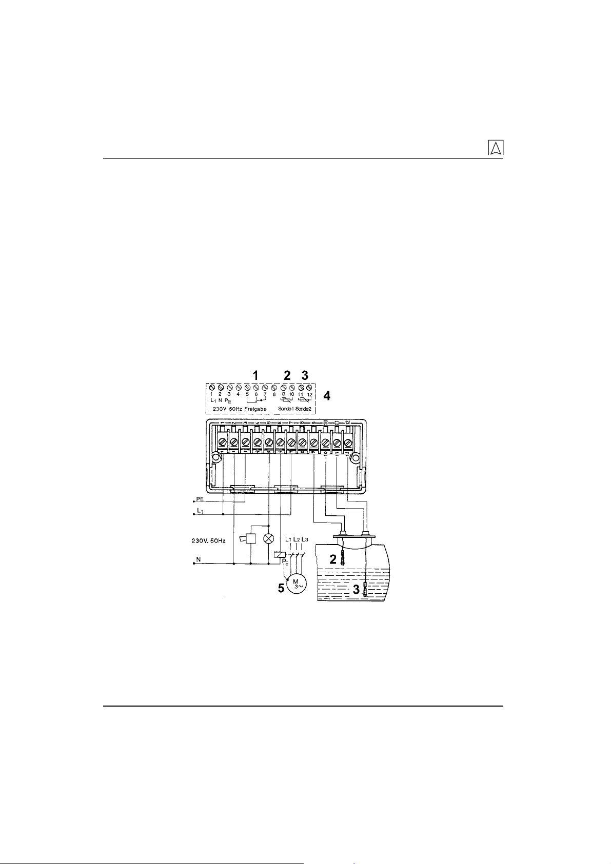
6.2 Electrical connection
;
Mains supply is disconnected and cannot be switched back on
by accident.
1Release
2Probe 1
3Probe 2
4Wiring diagram in
housing
5Pump
Fig. 7: Electrical connection
Installation and commissioning
RG 210 15
Power supply
;
Connect the level switch to mains by means of a permanently
installed cable such as NYM-J 3 x 1.5 mm².
1. Route the mains cable through the upper rubber cable gland
into the black base of the control unit.
2. The phase must be connected to terminal L1 , the neutral con-
ductor to terminal N and the protective conductor to terminal PE.
The control unit supply cable should be able to be switched off and
have a separate fuse (max. 16 A).
Probe
;
Do not route the probe cable next to mains cables; danger of in-
terference.
;
Protect the probe cable from damage; use metal pipes, if re-
quired.
1. The probe cable(s) must be permanently installed.
2. Route it/them through the bottom rubber cable glands of the
black base and connect them to the corresponding "Probe" ter-
minal(s).
You do not have to ensure a specific polarity.
Standard screened cable 2 x 0.5 mm² can be used to extend the
probe cable. The maximum length of the extension cable is 50 m.
Output
The output signal of RG 210 is made available via a voltage-free re-
lay contact (1 changeover contact).
1. The connection cable must be permanently installed.
2. Route it through the middle rubber cable gland of the black base
and connect it to the corresponding "Release" terminals.
CAUTION The switching contact may be destroyed by voltage peaks when
inductive consumers are switched off.
X Use commercially available standard RC combinations such as
0.1 µF/100 Ohm for inductive consumers.
Installation and commissioning
16 RG 210
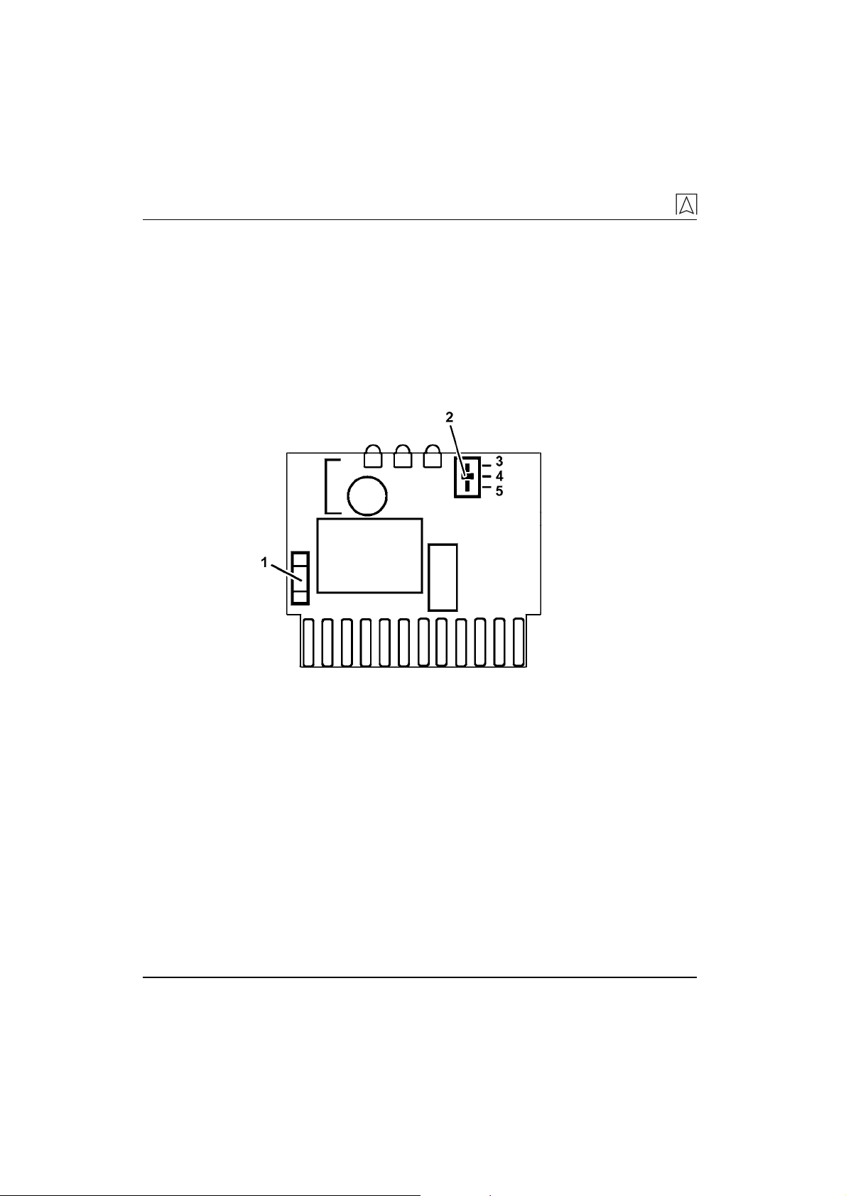
6.3 Selecting the operating mode
;
The grey upper part of the housing has been removed from the
black base.
1. Loosen the grey cover from the upper part of the housing by
means of a small screwdriver and pull the printed circuit board
out of the upper part of the housing.
2. Set the slide switch (2) next to the green LED to the desired po-
sition.
3. Reassemble the device.
1Mains fuse F1
2Slide switch for
operating modes
3Operating mode
“Probe 1”
4Operating mode
“Filling”
5Operating mode
“Emptying”
Fig. 8: Selecting the operating mode
6.4 Commissioning the device
;
Control unit and probe(s) have been installed as per chapter 6,
page 13.
;
Electrical connection has been completed as per chapter 6.2
page 14.
;
Wiring has been checked.
;
Desired operating mode has been selected.
;
Control unit housing has been closed with screws.
If all prerequisites are met, the device is ready for operation.
1. Switch on the power supply via the on-site mains fuse.
ª
The connected PTC thermistor heats up.

Operation
RG 210 17
ª
The connected PTC thermistor(s) are heated up after approx.
8 seconds, provided they are not submerged in liquid.
2. Perfom a function test, refer to chapter 6.5, page 17.
6.5 Function test
1. Submerge the probe(s) in liquid.
ª
The yellow LEDs must light up immediately.
2. Remove probe(s) from the liquid.
ª
After approx. 8-15 seconds the yellow LEDs must change the
switching state.
3. Observe the green LED and the relay.
ª
The function sequence must correspond to the description of the
selected operating mode in chapter 3.1, page 7.
7 Operation
RG 210 automates the control of pumps and valves. The operation
of the RG210 is limited to its regular monitoring:
• Function check OK.
• Probe free from deposits.
8 Maintenance
8.1 Maintenance intervals
Table 4: Maintenance intervals
When Activity
Once per
year
X Perfom an operation test.
X Check the probe(s) for deposits.
There must be no deposits on the glass housing
of the PTC thermistor. If the PTC thermistor is pol-
luted, replace probe(s).
At regular
intervals
X Perform suitable checks to ensure that the level
switch and its environment are always clean, ac-
cessible and easy to oversee.

Troubleshooting
18 RG 210
8.2 Maintenance activities
Replacing the mains fuse F1
;
Mains voltage is interrupted and cannot be switched on by acci-
dent.
1. Loosen the two housing screws.
2. Remove the grey upper part of the housing from the black base.
3. Remove the grey cover from the upper part of the housing.
4. Pull the printed circuit board out of the upper part of the hous-
ing.
5. Replace the mains fuse F1, refer to table 1, page 10.
6. Push the printed circuit board into the upper part of the housing.
7. Fit the grey cover onto the upper part of the housing.
8. Push the upper part of the housing onto the black base.
9. Screw in the two housing screws.
10. Switch on the mains voltage.
9 Troubleshooting
Repair work may only be carried out by qualified, specially trained
personnel.
Table 5: Troubleshooting
Problem Possible reason Remedy
Mains voltage
interrupted.
X Check mains voltage.
Mains fuse de-
fective.
X Replace the mains
fuse, refer to chap-
ter 8.2, page 18.
Wiring defective. X Check wiring.
Yellow LEDs do not
respond when the
probe changes its
state.
Probe(s) defec-
tive.
X Check probe(s).
PTC thermistor is
polluted (deposits).
-X Replace probe(s).

Shutting down and disposal
RG 210 19
Problem Possible reason Remedy
Wrong operating
mode selected.
X Check operating
mode.
Wiring defective. X Check wiring.
Probes inter-
changed.
X Check probes.
Green LED and the
relay do not switch
as described in
chapter 3.1, page 7.
Control unit de-
fective.
X Replace control unit.
Other malfunction. – X Return the device to
the manufacturer.
10 Shutting down and disposal
1. Disconnect mains supply.
2. Remove the device (see chapter 6, page 13, reverse sequence
of steps).
3. To protect the environment, this device must not be disposed of
together with the normal household waste. Dispose of the de-
vice according to the local conditions and directives.
This device consists of materials that can be reused by recycling
firms. The electronic inserts can be removed easily and are con-
structed from recyclable materials.
If you do not have the opportunity to dispose of the old device in ac-
cordance with environmental regulations, please contact us for pos-
sibilities to dispose of it or to return it.
11 Spare parts and accessories
Part Part No.
Control unit 53206
PTC thermistor probes type 150 53208
PTC thermistor probes type 937 53204
Cable extension fitting KVA 40041
Mains fuse F1 (M 100 mA) 941571 0100
RC combination (0,1 µF/100 Ohm) 618 001 5100
Brass weight for probe installation 16 00 020901
Clamp for probe installation 16 00 101001
Event reporting system Phone Alarm SD1 90003

Warranty
20 RG 210
Part Part No.
Event reporting system GSM Alarm 90002
Event reporting system EMS 220 90220
Event reporting system EMS 442 90442
12 Warranty
The manufacturer’s warranty for this product is 24 months from date
of purchase. This warranty applies to all countries in which this pro-
duct is sold by the manufacturer or its authorised representatives.
13 Copyright
The manufacturer holds the copyright to this manual. This manual
may only be reprinted, translated, copied in part or in whole with the
prior written consent of the manufacturer.
We reserve the right to modify any specifications or alter any illustra-
tions in this manual without prior notice.
14 Customer satisfaction
Customer satisfaction is our prime objective. Please get in touch with
us if you have any questions, suggestions or problems concerning
your product.
15 Addresses
The addresses of our worldwide representatives can be found on the
Internet at www.afriso.com.
Table of contents
Other Afriso EURO-INDEX Controllers manuals


