AFRISO PrimoBox AZB Specification sheet

Read the manual before using the device
Pay attention to all information regarding safety
Keep the Operation and installation manual
954.001.0001
AFRISO sp. z o.o.
Szałsza, ul. Kościelna 7
42-677 Czekanów
POLAND
Telefon +48 32 330 33 55
Fax +48 32 330 33 51
www.afriso.pl
Operation and installation manual
PrimoBox AZB mixing units with low-loss header
200 and 300 series in cabinets

2 PrimoBox AZB mixing units with low-loss header 200 and 300 series in cabinets
Table of Contents
1Explanations to the installation and operation manual............................................3
1.1 Safety messages and hazard categories.....................................................3
2Information on safety...............................................................................................3
2.1 Intended use.................................................................................................3
2.2 Quality control ..............................................................................................4
2.3 Qualification of personnel.............................................................................4
2.4 Modifications to the product .........................................................................4
2.5 Using additional parts and accessories .......................................................4
2.6 Liability .........................................................................................................4
3Product description..................................................................................................5
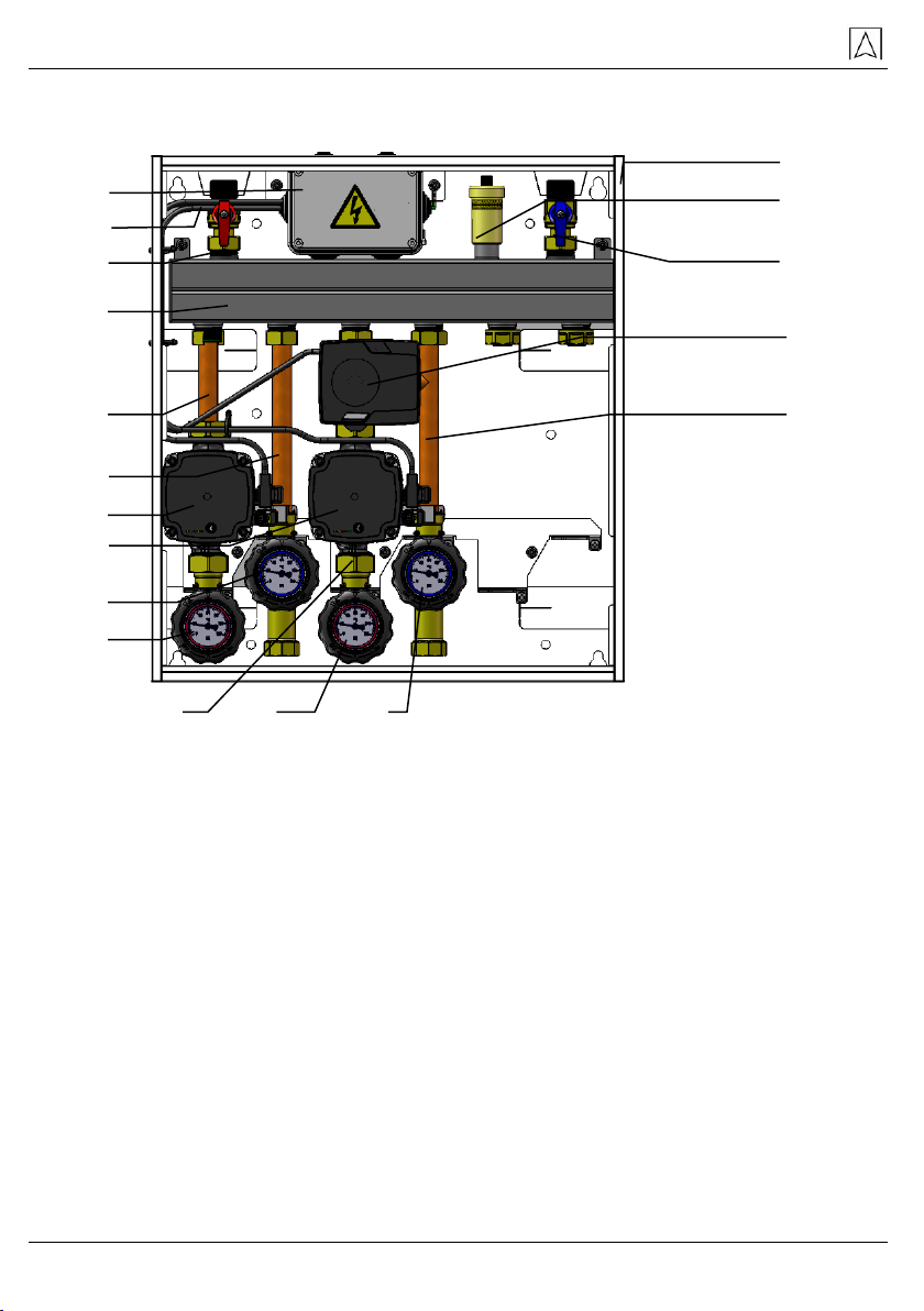
3.1 Construction.................................................................................................6
3.2 Dimensions...................................................................................................7
3.3 Operation......................................................................................................7
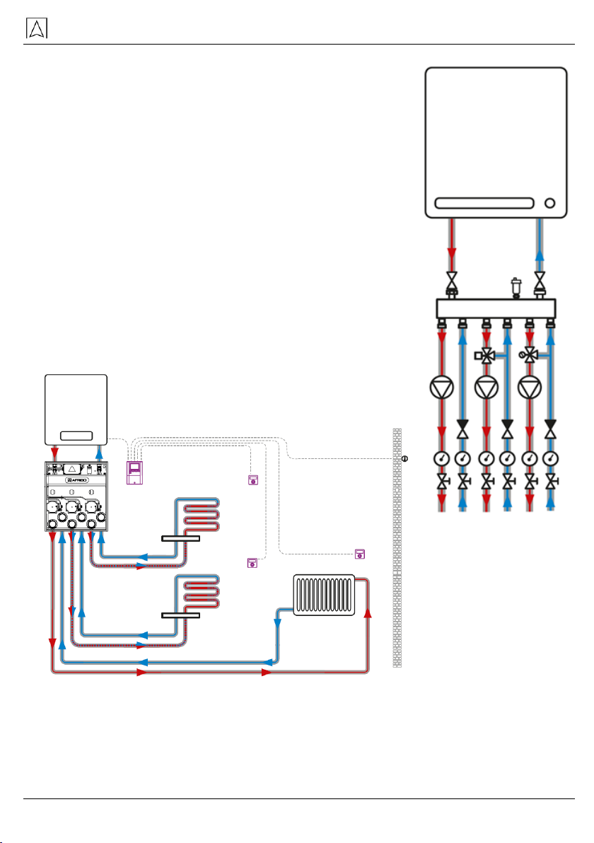
3.4 Hydraulic diagram sample............................................................................9
3.5 Sample application diagrams.......................................................................9
4Specification ..........................................................................................................10
4.1 Approvals ...................................................................................................10
4.2 Flow and available pressure diagrams ......................................................11
5Transport and storage...........................................................................................12
6Installation and commissioning .............................................................................13
6.1 Wall mounting.............................................................................................13
6.2 Flush mounting...........................................................................................14
6.3 Hydraulic connections................................................................................14
6.4 Electrical connections ................................................................................16
7Assembly and disassembly of ARM ProClick actuators........................................18
8Switching the actuator to manual operation..........................................................19
9Temperature setpoint with ATM thermostatic valve..............................................19
10 Decommissioning, scrapping ................................................................................20
11 Warranty................................................................................................................20
12 Copyright ...............................................................................................................20
13 Customer satisfaction............................................................................................20
14 Addresses..............................................................................................................20

Instruction manual
PrimoBox AZB mixing units with low-loss header 200 and 300 series in cabinets 3
1Explanations to the installation and operation manual
Installation and operating instructions are an important part
of the delivery. That is why we recommend:
Read the installation and operating instruction before installing
the device.
Keep the installation and operating instruction for the entire life
of the device.
Hand over the installation and operating instructions to any sub-
sequent owner or user of the device.
1.1 Safety messages and hazard categories
DANGER
Specifies the type and source of the threat.
Describes what to do to avoid a hazard.
Threats have 3 levels:
Danger
Importance
DANGER
DANGER indicates a hazardous situation, which,
if not avoided, will result in death or serious injury.
WARNING
WARNING indicates a potentially hazardous situa-
tion, which, if not avoided, can result in serious in-
jury or equipment damage.
NOTICE
NOTICE indicates a hazardous situation, which,
if not avoided, can result in equipment damage.
2Information on safety
2.1 Intended use
Mixing units PrimoBox AZB 200 and 300 series are a compact,
prefabricated solution enabling quick and convenient connection
of a heat source and two or three heating circuits in closed installa-
tions made in accordance with EN 12828.
Mixing units AZB series 200 and 300 are intended for separating
the medium into two or three heating zones. Depending on the version,
individual zones can be supplied with medium of the temperature
obtained at the outlet from the heat source (direct circuits, without
mixing), as well as of a lower temperature, obtained by mixing.
Any other use than indicated in point 2.1 is forbidden.

Instruction manual
4 PrimoBox AZB mixing units with low-loss header 200 and 300 series in cabinets
2.2 Quality control
Construction of mixing units PrimoBox AZB complies with the current
state of the technical standards regarding safety. Each device
is checked for safety before shipment.
The product should only be used if it is in a qualified technical
condition. Read the instructions for assembly and use as well as
observe the relevant safety regulations.
WARNING
Mains voltage (230 V AC) can cause serious injury or death.
Do not allow the device cover to come into contact with water.
Disconnect the device from the mains before opening the cover.
Disconnect the device from the mains before servicing.
Do not make any changes to the device.
2.3 Qualification of personnel
Mixing units PrimoBox AZB series 200 and 300 may only be installed,
commissioned, shut down and disassembled by suitably qualified
and trained personnel. Work on electrical circuits should only be
carried out by an authorized electrician.
2.4 Modifications to the product
Changes and modifications carried out by unauthorized persons may
cause hazards and are prohibited for safety reasons.
2.5 Using additional parts and accessories
Improper additional parts and accessories may damage the device.
Use only original spare parts and accessories
from the manufacturer.
2.6 Liability The manufacturer is not responsible for direct damages
or their consequences resulting from inaccurate reading of assembly
and usage instructions and recommendations.
The manufacturer and the company selling the device
are not responsible for damages and costs incurred by the user
or third parties using the device, in particular for damage resulting from
improper use indicated in chapter 2.1 of assembly and use
instructions, improper or faulty connection or maintenance and non-
compliant operation with manufacturer's recommendations.

Instruction manual
PrimoBox AZB mixing units with low-loss header 200 and 300 series in cabinets 5
AFRISO sp. z o.o. makes every effort to ensure that the information
materials do not contain errors.If errorsor inaccuracies arefound in the
following installation and operation instructions, please contact:
3Product description
PrimoBox AZB mixing units are available in versions supplying two
or three heating circuits.
PrimoBox AZB mixing units with a low-loss header secure the correct
flow rate of the medium and the correct operation of the pumps in all
heating circuits. They also allow obtaining different flow temperatures
of individual heating circuits.
The PrimoBox AZB mixing unit is enclosed in a metal cabinet. Inside
the cabinet there is a manifold with a built-in low-loss header ensuring
independent operation of individual heating circuits, while minimizing
the impact of circulation pumps on the heat source.
There are versions with heating circuits without mixing, with mixing
by an ARM ProClick actuator on a rotary valve or by mixing with
an ATM thermostatic mixing valve.
Two-section versions of AZB mixing units are made based
on the same manifold as three-section version, but only two pairs
of connections are used.

Instruction manual
6 PrimoBox AZB mixing units with low-loss header 200 and 300 series in cabinets
3.1 Construction
1- shut-off valve with thermometer
2- Grundfos UPM3 AUTO 15-70 130 mm pump
3- zone 1 return pipe
4- zone 2 return pipe
5- rotary valve with ARM ProClick actuator
6- primary circuit return shut-off valve
7- primary circuit supply shut-off valve
8- automatic air vent
9- cabinet
10-electrical box
11-manifold
12-zone 1 supply pipe
13-electric wires
14-zone 2 supply pipe
Fig. 1: Construction of AZB 205 mixing unit
1
1
1
2
2
1
3
4
5
6
7
10
9
11
12
10
14
13
3

Instruction manual
PrimoBox AZB mixing units with low-loss header 200 and 300 series in cabinets 7
3.2 Dimensions
Fig. 2: Dimensions of the AZB mixing unit
In the two-zone version equipped with two ATM thermostatic mixing
valves (Art. No. 76 211 00), middle and right connections are used
to facilitate operation of the thermostatic valve knobs.
3.3 Operation
The mixing unit PrimoBox AZB with low-loss header is designed
to divide the heating medium flow from the boiler circuit into two
or three heating circuits. The manifold used with a built-in low-loss
header eliminates the need to balance the primary circuit of the boiler
with other circuits. This ensures smoothness and high efficiency
of the installation operation regardless of the current hydraulic
conditions and the current demand for heating power.
Using the PrimoBox AZB mixing unit with low-loss header allows
reducing the use of number of fittings and pipes necessary to perform
individual installation circuits, and helps to organize and simplifie
the entire installation.

Instruction manual
8 PrimoBox AZB mixing units with low-loss header 200 and 300 series in cabinets
Shut-off valves with thermometers
AZB mixing units are supplied with built-in shut-off valves to facilitate
product maintenance. Check valves have been built into the shut-off
valves. Space for temperature sensors has also been prepared.
The valve knobs contain thermometers to control the temperature
of the heating medium. By turning the knob by 45°, the non-return valve
is forced to open to enable system maintenance and system filling.
Grundfos UPM3 AUTO 15-70 circulation pumps
For the operation of the Grundfos UPM3 AUTO circulation pumps
included in the PrimoBox units, please refer to the attached operating
instructions (also available on the manufacturer's website).
Connections for AZB mixing units
heat source
zone 1
zone 2
zone 3
Fig. 3: Connections
of PrimoBox AZB 351
mixing unit

Instruction manual
PrimoBox AZB mixing units with low-loss header 200 and 300 series in cabinets 9
3.4 Hydraulic diagram sample
Fig. 4: PrimoBox AZB 351 hydraulic diagram
3.5 Sample application diagrams
Fig. 5: Sample application diagram - 2 circuits of underfloor heating system
and a radiator system circuit
1
2
3
4
5
6
7
2
4.
2.
3.
1.
3.
1. AZB mixing unit
2. Installation controller
3. Underfloor heating circuit
4. Radiator circuit

Instruction manual
10 PrimoBox AZB mixing units with low-loss header 200 and 300 series in cabinets
4Specification
Table 1: Technical data of AZB 200 & 300 units
Parameter / part
Value / Description
General specification
Dimensions (W x H x D)
450 x 500 x 160mm
Weight
13 ÷ 22 kg
Circulation pumps
Grundfos UPM 3 AUTO 15-70 130 mm
Thermostatic mixing valve
ATM 561 with Kvs 2.5 with 20-43°C control
Rotary mixing valve
Kvs 3,6 with 3-point ARM ProClick
230 V AC 50 Hz
Water capacity of the manifold
with low-loss header
1,5 l
Pressure
max 4,5 bar
Heat source connections
G¾”
Connection of individual zones
famale G¾”
Heating medium temperature
5°C ÷ 95°C
Glycol concentration
max 30%
Installation power
max 35 kW
Supply voltage
Supply voltage
230 V AC ± 10%, 50 Hz
Power consumption
max 52 W
Housing protection
IPX 0
4.1 Approvals
Mixing units with manifold AZB series 200 and 300 are subject
to the Pressure Directive 2014/68/EU and in accordance
with art. 4.3 (sound engineering practice) are not CE marked.
Circulation pumps included in the product have a declaration of con-
formity, which is available on the manufacturer's website.
The ARM ProClick electric actuators used in the AZB units comply
with EU directives on low voltage electrical equipment LVD
(2014/35/EU) and electromagnetic compatibility EMC (2014/31/EU).

Instruction manual
PrimoBox AZB mixing units with low-loss header 200 and 300 series in cabinets 11
4.2 Flow and available pressure diagrams
Fig. 6: Graph of flow rate and disposal pressure through a direct circuit
Fig 7: Graph of flow rate and disposal pressure through a circuit
with rotary mixing valve

Instruction manual
12 PrimoBox AZB mixing units with low-loss header 200 and 300 series in cabinets
Fig. 8: Graph of flow rate through the circuit with ATM thermostatic
mixing valve
5Transport and storage
ATTENTION
Possibility of damage to the device during improper transport.
Do not throw the device.
Protect against water, moisture, dirt and dust.
ATTENTION
Possibility of damage during incorrect storage.
Store the device in a dry and clean room.
Protect against water, moisture, dirt and dust.

Instruction manual
PrimoBox AZB mixing units with low-loss header 200 and 300 series in cabinets 13
6Installation and commissioning
The place where the AZB kit is installed must provide weather protec-
tion. The AZB module must not be installed outdoors. The AZB unit
is designed for wall mounting or to embed it in the wall. It cannot be
mounted on stands or placed directly on the floor.
ATTENTION
Possible damage to existing installations
When drilling into walls, pay special attention not to damage
electric cables or other existing cables.
6.1 Wall mounting
On the selected, straight wall, mark the places provided for the han-
dles so that they coincide with the holes in the back of the PrimoBox
AZB mixing unit. Drill holes in the wall and place the dowels (included
in the delivery) in them. Hang the module on the dowels. Then check
the correct leveling.
Fig. 9: Spacing of mounting holes

Instruction manual
14 PrimoBox AZB mixing units with low-loss header 200 and 300 series in cabinets
ATTENTION
Possible need for other dowels
It is necessary to verify that the dowels provided are suitable
for the selected wall.
If the dowels provided are not suitable for the selected wall,
replace them with others.
Mounting the AZB unit on the improper dowels can lead to its
breaking off the wall!
6.2 Flush mounting
Check whether the wall is strong and thick enough and that
the PrimoBox AZB mixing kit will fit in the place you choose.
To install the PrimoBox AZB mixing kit in the wall, breach the fins
placed in the housing and bend them with pliers so that they
are outside the unit housing (Figure 10).
Then create a space in the wall, at least 2 cm larger than the external
dimensions of the housing of the AZB mixing kit. Fasten the module
in the hole in the wall
with plaster or other suitable
compound. Remember to
level it carefully using a spirit
level.
After drying, if necessary,
make an aesthetic finish
of the wall.
Fig. 10: Bending
of the housing fins
6.3 Hydraulic connections
Before connecting the AZB
mixing unit, flush the system
thoroughly, paying special at-
tention to removing residue from soldering, cutting pipes, etc.
Make sure that the installation contains safety components necessary
for proper and safe functioning. We recommend installing strainers
before inlet connections. The heating installation should also contain
filters, dirt separators or other similar filtering elements.

Instruction manual
PrimoBox AZB mixing units with low-loss header 200 and 300 series in cabinets 15
6.3.1 Connection of the primary circuit
6.3.1.1 Connection to the heat source
The connection between the AZB mixing unit and the heat source (e.g.
gas boiler) takes place via the supply and return connections at the
top of the unit. The connection should be made by G¾ male threads.
6.3.1.2 Connection with the AFRISO PrimBox AHB separation unit
AZB mixing units can be com-
bined with the AHB 620
and AHB 622 separation units
to form a heating column
with the function of separating
two heat sources and all func-
tions of the AZB sets.
This connection is carried
out by the AJB 110 junction kit
(Art. No. 76 110 00).
The figure shows a heating col-
umn built from the connected
AHB and AZB units.
Figure 11: Heating column:
AHB + AJB + AZB units

Instruction manual
16 PrimoBox AZB mixing units with low-loss header 200 and 300 series in cabinets
6.3.2 Connection of individual heating circuits
The connection between the mixing unit and the heating system is
made by pairs of supply/return connections located at the bottom
of the AZB mixing unit 200 series (2 pairs) or 300 (3 pairs).
The PrimoBox AZB 200 and 300 mixing units are equipped
with threaded female G¾" connections.
6.4 Electrical connections
Make sure that the power supply has been disconnected and
protected against accidental switching on.
Safety regulations and other relevant accident prevention regulations
must be observed. You should also comply with all applicable national
laws. The PrimoBox AZB mixing unit is connected to 230V AC.
PrimoBox mixing units have a built-in electrical box. All necessary
cables have already been distributed from the electrical box.
WARNING
Do not allow actuators, built-in electrical box and cables into
contact with water.
An example of cable distribution is shown in Fig. 12.
The number of electric wires varies depending on the number of elec-
tric actuators and pumps in the set.
Fig. 9: Sample distribu-
tion of electric wires

Instruction manual
PrimoBox AZB mixing units with low-loss header 200 and 300 series in cabinets 17
Depending on the version, it is necessary to make additional connec-
tions of pumps and electric actuatirs with the controller or controllers
via the built-in electrical box.
In this case, make an electrical connection of the controller
with the AZB mixing unit according to the diagram (Fig. 13).
Fig. 10: Electrical diagram of the mixing unit PrimoBox AZB 355
with two ARM ProClick actuators
ARM ProClick actuators must be electrically connected to a suitable
3-point controller with a 230 V AC control signal.
In the version of the AZB 365 mixing unit with three actuators,
one of the actuatirs is connected via a loose triple connection block
placed inside the electric box - see Fig. 14.
Fig. 14: Electrical diagram of connecting the third ARM ProClick actu-
ator in the AZB 365 mixing kit through a loose connection block.
The actuator power cord is detachable, which simplifies installation
and electrical work. To remove the plug from the actuator, pry the lid
latch lever and slide the cover off the actuator housing (Fig. 15),
then unplug the plug (Fig. 16). The plug fits into the socket only in one
position.

Instruction manual
18 PrimoBox AZB mixing units with low-loss header 200 and 300 series in cabinets
Fig. 11:Removing the lid
Fig. 12: ARM ProClick
actuator plug
7Assembly and disassembly of ARM ProClick actuators
The PrimoBox AZB unit is equipped with ARM ProClick electric actu-
ators. They can be easily disassembled and reassembled.
The ARM ProClick actuators are removed from the valve by pressing
the button on the side of the actuator housing and pulling the actuator
towards you.
Fig. 13: Actuator latch release
button
To mount the ARM ProClick ac-
tuator on the mixing valve
of the AZB unit, the mixing
valve must be set to "50%
opening", i.e. the center of its valve is exactly halfway between the hot
water inlet and the cold water inlet. Then slide the actuator onto the
mixing valve until the ProClick mechanism locks on it. When mounting
the ProClick actuator on a rotary valve, pay attention to the current
position of the valve cover. The valve stem should be positioned
as in Figure 19, and the actuator position indicator should show half
the scale. If the valve is in a different position, set it manually (using
a flat screwdriver, for example) as shown in Fig-
ure 19. If the indicator on the actuator does not
indicate the center of the scale, switch it to man-
ual operation mode, set the actuator with the al-
len key so that the indicator is in the center of
the scale. After putting the actuator
on the valve, switch back to automatic mode.
Fig.18: Correct position of the rotary mixing
valve when installing the actuator

Instruction manual
PrimoBox AZB mixing units with low-loss header 200 and 300 series in cabinets 19
8Switching the actuator to manual operation
Switching from automatic to manual oper-
ation is carried out by operating the mode
button. The pressed mode button enables
manual operation, i.e. free operation of the
actuator with an allen key.
Fig. 14: Actuator mode buton
9Temperature setpoint with ATM thermostatic valve
The temperature of the heating medium at the MIX outlet of the ATM
valve is set by a knob, according to the following table.
setpoint
temperature
1
20°C
2
25°C
3
29°C
4
33°C
5
37°C
6
43°C
Fig. 20: ATM 561 thermostatic valve knob
The selected setting on the knob should correspond to the blue
arrow-shaped indicator.

Instruction manual
20 PrimoBox AZB mixing units with low-loss header 200 and 300 series in cabinets
10 Decommissioning, scrapping
1. Disconnect the device's power supply.
2. Disassemble the device (see chapter 6, reverse order).
3. In the interests of environmental protection, do not dispose
of the device when it is out of service with unsorted household
waste. The device should be delivered to an appropriate
recycling facility.
The AZB 200 and 300 series mixing units are made of materials that can
be recycled.
11 Warranty
The manufacturer’s warranty for this product is 36 months after the date
of purchase from AFRISO sp. z o.o.. In case of any alteration in the prod-
uct or usage against this instruction manual, the warranty becomes void.
12 Copyright
Copyrights to the manual belong to AFRISO sp.z o.o. Reprinting,
translation and reproduction, even partial, is prohibited without written
permission. Changing technical details, both in writing and in the form
of images, is prohibited by law. We reserve the right to make changes
without prior notice.
13 Customer satisfaction
For AFRISO sp.z o.o. customer satisfaction is the most important thing.
If you have questions, suggestions or problems with the product, please
contact: zok@afriso.pl, phone number +48 32 330 33 55.
14 Addresses
The addresses of companies representing the AFRISO group around
the World can be found at www.afriso.com.
Table of contents
Other AFRISO Industrial Equipment manuals