AGI BATCO 1800 Series User manual

Read this manual before using product. Failure to
follow instructions and safety precautions can
result in serious injury, death, or property
damage. Keep manual for future reference.
Part Number: P1512180 R0
Revised: December 2019
Pitstop Drive Kits Assembly
Manual
Original instructions
This manual applies to:
AGI BATCO 1800, 2400 Series
AGI HUTCHINSON 1800, 2400 Series
AGI WESTFIELD 1800, 2400 Series
Gas, Electric, and Hydraulic Drives
Original Instructions

2 P1512180 R0
PITSTOP DRIVE KITS ASSEMBLY MANUAL –

PITSTOP DRIVE KITS ASSEMBLY MANUAL –
P1512180 R0 3
CONTENTS
1. Safety....................................................................................................................................................... 4
1.1 Safety Alert Symbol and Signal Words...................................................................................... 4
1.2 General Product Safety ............................................................................................................. 4
1.3 Moving Conveyor Belt Safety.................................................................................................... 4
1.4 Rotating Parts Safety................................................................................................................. 5
1.5 Work Area Safety ...................................................................................................................... 5
1.6 Guards Safety ............................................................................................................................ 5
1.7 Drives and Lockout Safety......................................................................................................... 5
1.7.1 Gas Engine Safety....................................................................................................... 6
1.7.2 Electric Motor Safety.................................................................................................. 6
1.7.3 Hydraulic Power Safety .............................................................................................. 7
1.8 Tire Safety.................................................................................................................................. 8
1.9 Personal Protective Equipment................................................................................................. 8
1.10 Safety Equipment .................................................................................................................... 9
1.11 Safety Decals ........................................................................................................................... 9
1.11.1 Decal Installation/Replacement............................................................................... 9
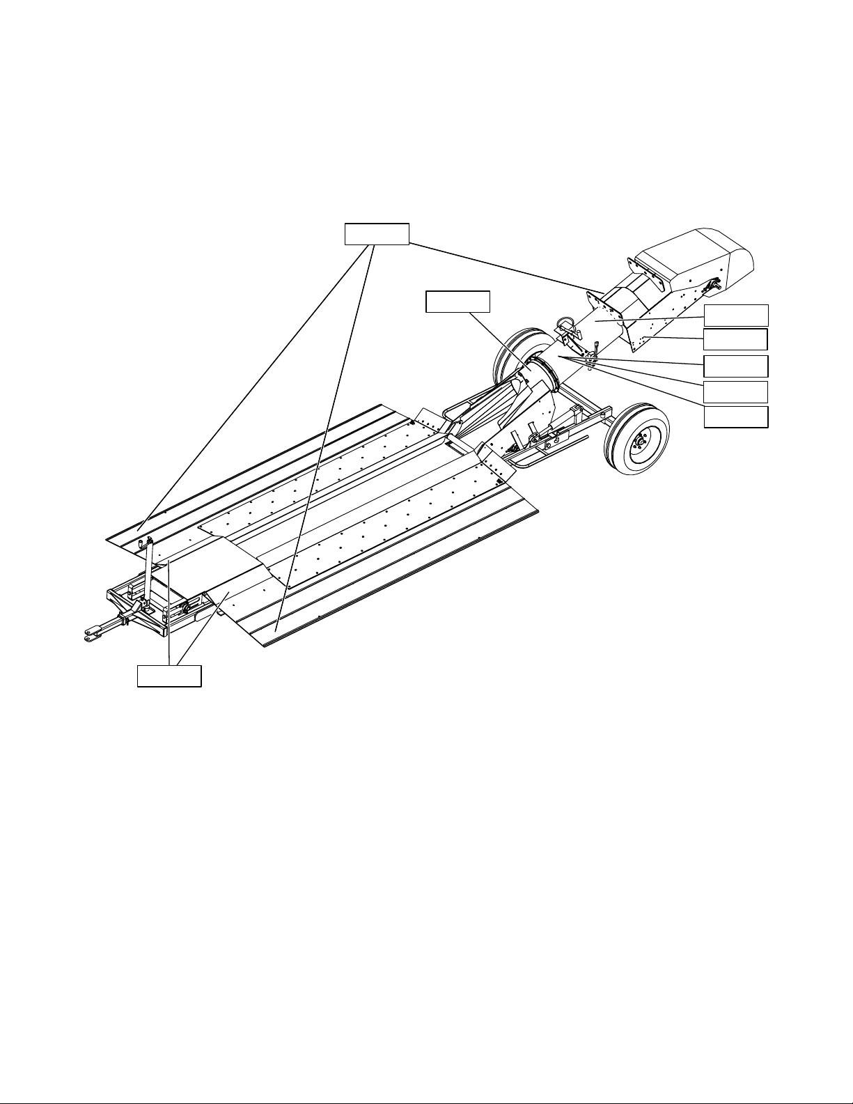
1.11.2 Safety Decal Locations and Details ........................................................................ 10
2. Assembly ............................................................................................................................................... 17
2.1 Assemble the Lift Hose............................................................................................................ 17
2.2 Install the Electric Drive .......................................................................................................... 18
2.2.1 Assemble the Motor Mounts................................................................................... 19
2.2.2 Install the Motor Mounts and Rails ......................................................................... 20
2.2.3 Install the Guard Mounting Brackets....................................................................... 21
2.2.4 Install the Motor ...................................................................................................... 22
2.2.5 Install the Pulleys, Drive Belts, and Tensioning Bolt................................................ 23
2.2.6 Install the Drive Belt Guard...................................................................................... 24
2.2.7 Install the Shaft Guard ............................................................................................. 25
2.3 Install the Hydraulic Wet Kit for the Electric Drive................................................................. 26
2.3.1 Install the Hydraulic Pump ....................................................................................... 27
2.3.2 Install the Hydraulic Tank......................................................................................... 32
2.3.3 Install the Hydraulic Fittings into the Flow Controller............................................. 33
2.3.4 Install the Hoses ....................................................................................................... 34
2.4 Install the Gas Drive ................................................................................................................ 35
2.4.1 Install the Drive and Battery Mounts....................................................................... 36
2.4.2 Install the Motor and Gearbox................................................................................. 40
2.4.3 Install the Battery and Fuel Tank ............................................................................. 46
2.4.4 Install the Guards ..................................................................................................... 49
2.5 Install the Hydraulic Drive ....................................................................................................... 52
2.5.1 Install the Hydraulic Motor ...................................................................................... 53
2.5.2 Install the Flow Controller........................................................................................ 58
2.5.3 Install the Hydraulic Fittings into the Lift Control ................................................... 62
2.5.4 Install the Hoses ....................................................................................................... 63
3. Limited Warranty.................................................................................................................................. 64

4 P1512180 R0
1. Safety
1.1. Safety Alert Symbol and Signal Words
This safety alert symbol indicates important safety messages in this manual. When you see
this symbol, be alert to the possibility of injury or death, carefully read the message that
follows, and inform others.
Signal Words: Note the use of the signal words DANGER,WARNING,CAUTION, and NOTICE with the safety
messages. The appropriate signal word for each message has been selected using the definitions below as a
guideline.
Indicates an imminently hazardous situation that, if not avoided, will result in serious injury or
death.
Indicates a hazardous situation that, if not avoided, could result in serious injury or death.
Indicates a hazardous situation that, if not avoided, may result in minor or moderate injury.
Indicates a potentially hazardous situation that, if not avoided, may result in property damage.
1.2. General Product Safety
It is the owner, operator, and maintenance personnel's responsibility to read and understand all safety
instructions, safety decals, and manuals and follow them when operating or maintaining the equipment.
• Owners must give instructions and review the information initially and annually with all personnel before
allowing them in the work area. Untrained users/operators expose themselves and bystanders to possible
serious injury or death.
• Use for intended purposes only.
• Do not modify the conveyor in any way without written permission from the manufacturer. Unauthorized
modification may impair the function and/or safety. Any unauthorized modification will void the warranty.
• Follow a health and safety program for your worksite. Contact your local occupational health and safety
organization for information.
1.3. Moving Conveyor Belt Safety
• DO NOT step on or touch moving conveyor belt.
• Shut off and lock out power to adjust, service, or clean.
1. SAFETY PITSTOP DRIVE KITS ASSEMBLY MANUAL –

P1512180 R0 5
1.4. Rotating Parts Safety
• Keep body, hair, and clothing away from rotating pulleys,
belts, chains, and sprockets.
• Do not operate with any guard removed or modified. Keep
guards in good working order.
• Shut off and remove key or lock out power source before
inspecting or servicing machine.
1.5. Work Area Safety
• Have another trained person nearby who can shut down the conveyor in case of accident.
• The work area should be kept clear of bystanders, including children.
• Keep the work area clean and free of debris.
1.6. Guards Safety
• Keep guards in place. Do not operate with guard removed.
• Do not walk on, step on, or damage guards.
• Lock out power before removing a guard.
• Ensure all guards are replaced after performing maintenance.
1.7. Drives and Lockout Safety
Inspect the power source(s) before using and know how to shut down in an emergency.
Whenever you service or adjust your equipment, make sure you shut down the power
source and unplug or remove the key (as applicable) to prevent inadvertent start-up and
hazardous energy release. Know the procedure(s) that applies to your equipment from the
following power source(s). Ensure that all personnel are clear before turning on power to
equipment.
PITSTOP DRIVE KITS ASSEMBLY MANUAL – 1. SAFETY

6 P1512180 R0
1.7.1 Gas Engine Safety
Power Source
• Keep guards in place and secure.
• Properly ventilate surrounding area.
• Never fill the fuel tank with the engine running, while
smoking, or near an open flame. Always shut down and allow
engine to cool before filling with fuel.
• Never overfill the tank or spill fuel. If fuel is spilled, clean it
up immediately.
• Be sure to use the correct type and grade of fuel. Ground the
fuel funnel or nozzle against the filler neck to prevent sparks
that could ignite fuel vapors.
• Be sure to replace the fuel fill cap when you are done.
Lockout
• For engines with an electric start, remove the ignition key,
the spark plug wire, or the spark plug.
• For engines with a rope or crank start, remove the spark plug
wire or the spark plug.
1.7.2 Electric Motor Safety
Power Source
• Electric motors and controls shall be installed and serviced by
a qualified electrician and must meet all local codes and
standards.
• A magnetic starter should be used to protect your motor.
• You must have a manual reset button.
• Reset and motor starting controls must be located so that the
operator has full view of the entire operation.
• Locate main power disconnect switch within reach from
ground level to permit ready access in case of an emergency.
• Motor must be properly grounded.
• Guards must be in place and secure.
• Ensure electrical wiring and cords remain in good condition;
replace if necessary.
• Use a totally enclosed electric motor if operating in
extremely dusty conditions.
SERVICE DISCONNECT
ON
OFF
Lockout
• The main power disconnect switch should be in the locked position during shutdown or
whenever maintenance is performed.
• If reset is required, disconnect all power before resetting motor.
1. SAFETY PITSTOP DRIVE KITS ASSEMBLY MANUAL –

P1512180 R0 7
1.7.3 Hydraulic Power Safety
Power Source
• Refer to the rules and regulations applicable to the power
source operating your hydraulic drive.
• Do not connect or disconnect hydraulic lines while system is
under pressure.
• Keep all hydraulic lines away from moving parts and pinch
points.
• Escaping hydraulic fluid under pressure will cause serious
injury if it penetrates the skin surface (serious infection or
toxic reaction can develop). See a doctor immediately if
injured.
• Use metal or wood as a backstop when searching for
hydraulic leaks and wear proper hand and eye protection.
• Check all hydraulic components are tight and in good
condition. Replace any worn, cut, abraded, flattened, or
crimped hoses.
• Clean the connections before connecting to equipment.
• Do not attempt any makeshift repairs to the hydraulic fittings
or hoses with tape, clamps, or adhesive. The hydraulic
system operates under extremely high pressure; such repairs
will fail suddenly and create a hazardous and unsafe
condition.
Lockout
• Always place all hydraulic controls in neutral and relieve
system pressure before disconnecting or working on
hydraulic system.
PITSTOP DRIVE KITS ASSEMBLY MANUAL – 1. SAFETY

8 P1512180 R0
1.8. Tire Safety
Failure to follow proper procedures when mounting a tire on a
wheel or rim can produce an explosion that may result in
serious injury or death.
• DO NOT attempt to mount a tire unless you have the proper
equipment and experience to do the job.
• Have a qualified tire dealer or repair service perform
required tire maintenance.
• When replacing worn tires, make sure they meet the original
tire specifications. Never undersize the replacement tire.
• DO NOT weld to the tire rim with the tire mounted on the
rim. This action may cause an explosion which could result in
serious injury or death.
• Inflate tires to the manufacturer’s recommended pressure.
• Tires should not be operated at speeds higher than their
rated speed.
• Keep wheel lug nuts tightened to manufacturer’s
recommendations.
• Never reinflate a tire that has been run flat or seriously
under-inflated without removing the tire from the wheel.
Have the tire and wheel closely inspected for damage before
remounting.
1.9. Personal Protective Equipment
The following Personal Protective Equipment (PPE) should be worn when operating or maintaining the
equipment.
Safety Glasses
• Wear safety glasses at all times to protect eyes from debris.
Coveralls
• Wear coveralls to protect skin.
Hard Hat
• Wear a hard hat to help protect your head.
1. SAFETY PITSTOP DRIVE KITS ASSEMBLY MANUAL –

P1512180 R0 9
Steel-Toe Boots
• Wear steel-toe boots to protect feet from falling debris.
Work Gloves
• Wear work gloves to protect your hands from sharp and rough edges.
Dust Mask
• Wear a dust mask to prevent breathing potentially harmful dust.
1.10. Safety Equipment
The following safety equipment should be kept on site:
Fire Extinguisher
• Provide a fire extinguisher for use in case of an accident. Store in a highly visible and
accessible place.
First-Aid Kit
• Have a properly-stocked first-aid kit available for use should the need arise, and
know how to use it.
1.11. Safety Decals
• Keep safety decals clean and legible at all times.
• Replace safety decals that are missing or have become illegible. See decal location figures that follow.
• Replaced parts must display the same decal(s) as the original part.
• Replacement safety decals are available free of charge from your distributor, dealer, or factory as applicable.
1.11.1 Decal Installation/Replacement
1. Decal area must be clean and dry, with a temperature above 50°F (10°C).
2. Decide on the exact position before you remove the backing paper.
3. Align the decal over the specified area and carefully press the small portion with the exposed sticky backing
in place.
4. Slowly peel back the remaining paper and carefully smooth the remaining portion of the decal in place.
5. Small air pockets can be pierced with a pin and smoothed out using the sign backing paper.
PITSTOP DRIVE KITS ASSEMBLY MANUAL – 1. SAFETY

10 P1512180 R0
1.11.2 Safety Decal Locations and Details
Replicas of the safety decals that are attached to the conveyor and their messages are shown in the figure(s)
that follow. Safe operation and use of the conveyor requires that you familiarize yourself with the various safety
decals and the areas or particular functions that the decals apply to, as well as the safety precautions that must
be taken to avoid serious injury, death, or damage.
Figure 1. Safety Decal Locations
P1513002 P1513002
P1513008
P1513002
P1513039
P1513045
P1513035
P1513052
P1513001
1. SAFETY PITSTOP DRIVE KITS ASSEMBLY MANUAL –

12 P1512180 R0
Table 1. Safety Decals
Part Number Description
P1513001
To prevent serious injury or death:
• Read and understand the manual before
assembling, operating, or maintaining the
equipment.
• Only trained personnel may assemble, operate,
or maintain the equipment.
• Children and untrained personnel must be kept
outside of the work area.
• Do not modify the equipment. Keep in good
working order.
• If the manual, guards, or decals are missing or
damaged, contact factory or representative for
free replacements.
• Lock out power before performing maintenance.
• To prevent equipment collapse or upending,
support equipment tube while disassembling
certain components.
• Electric motors must be grounded. Disconnect
power before resetting overloads.
WARNING
1. SAFETY PITSTOP DRIVE KITS ASSEMBLY MANUAL –

P1512180 R0 13
Table 1 Safety Decals (continued)
Part Number Description
P1513002
To prevent serious injury or death:
• Keep body, hair, and clothing away from rotating
pulleys, belts, chains, and sprockets.
• Do not operate with any guard removed or
modified. Keep guards in good working order.
• Shut off and remove key or lock out power
source before inspecting or servicing machine.
ENTANGLEMENT HAZARD
WARNING
P1513008
To prevent serious injury or
death, shut off power and
reattach guard before operating
machine.
MISSING GUARD HAZARD
WARNING
PITSTOP DRIVE KITS ASSEMBLY MANUAL – 1. SAFETY

14 P1512180 R0
Table 1 Safety Decals (continued)
Part Number Description
P1513009
To prevent serious injury or death:
• Only qualified personnel should service
electrical components.
• Disconnect and lockout power before
inspecting or servicing unit.
• Keep electrical components in good repair.
ELECTROCUTION HAZARD
WARNING
P1513035
HIGH PRESSURE FLUID HAZARD
WARNING
Hydraulic fluid can cause serious injury if it
penetrates the skin. If it does, see a doctor
immediately.
• Relieve system pressure before repairing,
adjusting or disconnecting.
• Wear proper hand and eye protection when
searching for leaks. Use wood or cardboard
instead of hands.
Hydraulic fluid can cause serious injury if it
penetrates the skin. If it does, see a doctor
immediately.
• Relieve system pressure before repairing,
adjusting or disconnecting.
• Wear proper hand and eye protection when
searching for leaks. Use wood or cardboard
instead of hands.
1. SAFETY PITSTOP DRIVE KITS ASSEMBLY MANUAL –

P1512180 R0 15
Table 1 Safety Decals (continued)
Part Number Description
P1513039
For proper raising and lowering of equipment:
• After lowering equipment, always tighten brake lock
by turning winch handle clockwise at least two clicks.
• Rotate winch handle until cable has light tension,
when in towing position.
• Do not lubricate winch brake discs.
• Inspect lift cable periodically; replace if damaged.
• Inspect cable clamps periodically; tighten if necessary.
CAUTION
P1513045
To prevent death or serious injury:
• DO NOT step on or touch moving conveyor belt.
• Shut off and lock out power to adjust, service, or
clean.
OPEN BELT CONVEYOR
WARNING
PITSTOP DRIVE KITS ASSEMBLY MANUAL – 1. SAFETY

P1512180 R0 17
2. Assembly
Before continuing, ensure you have completely read and understood this manual’s
Safety section, in addition to the safety information in the section(s) below.
2.1. Assemble the Lift Hose
Figure 4. Assemble the Lift Hose
Item Description
1Lift Control
290° Swivel (#6 ORB to 1/2" FPT)
3Hex Nipple (1/2" PT)
41/2" Ball Valve
5Tee-Swivel (1/2" FEM)
63/8" X 2' Hose (1/2" MPT to 1/2" MPT PC)
7Swivel (3/8" MPT X 1/2"FPT)
83/8" X 3'7" Hose (1/2" MPT to 1/2" MPT PC)
93/8" X 10" Hose (10" MPT to 1/2" MPT PC)
Assembly Notes
• The swivels (7) are installed into the hydraulic cylinders on either side of the pitstop tube.
3
2
4
1
5
7
6
9
8
PITSTOP DRIVE KITS ASSEMBLY MANUAL – 2. ASSEMBLY

18 P1512180 R0
2.2. Install the Electric Drive
Installing the electric drive requires the completion of the following tasks:
Step Task
1Assemble the Motor Mounts
2Install the Motor Mounts and Rails
3Install the Guard Mounting Brackets
4Install the Motor
5Install the Pulleys, Drive Belts, and Tensioning Bolt
6Install the Drive Belts Guard
7Install the Shaft Guard
Figure 5. Electric Drive Overview
7
4
5
3
1
2
1
2. ASSEMBLY PITSTOP DRIVE KITS ASSEMBLY MANUAL –
This manual suits for next models
5
Table of contents
Other AGI Accessories manuals

AGI
AGI WESTFIELD 1500 Series User manual

AGI
AGI BCX3 1549 User manual

AGI
AGI HI ROLLER User manual

AGI
AGI Batco 1500 SA Series User manual

AGI
AGI WESTFIELD 1500 Series User manual

AGI
AGI DC User manual

AGI
AGI 1222 User manual

AGI
AGI Batco 1500 Series: Batco FX1535FL User manual

AGI
AGI WESTFIELD 1500 Series User manual
Popular Accessories manuals by other brands

La Crosse Technology
La Crosse Technology TX8U instruction manual

CMP
CMP DEL UV-C PRO 50 INSTALLATION INSTRUCTIONS & PRODUCT MANUAL

Lascal
Lascal Buggyboard-Mini owner's manual

Pepperl+Fuchs
Pepperl+Fuchs 3RG7256-3NQ00-PF Mounting and operating instructions

Froggit
Froggit DP150 manual

diversey
diversey MoonBeam 3 user manual