Aginova Sentinel RS-485 DO User manual

Sentinel (RS-485) DO
Operation Manual

Sentinel (RS-485) DO • Operation Manual
Table of Contents
Chapter 1 Specifications .............................................................................................................................. 1
Chapter 2 Product Presentation ................................................................................................................. 2
Chapter 3 Installation .................................................................................................................................. 3
3.1 Installation of Sensors .................................................................................................................... 3
3.1.1 Quick Dismantling pool side fixed installation .................................................................. 4
3.1.2 Classic pool side fixed installation ..................................................................................... 5
3.1.3 Railing fixed installation .................................................................................................... 6
3.2 Connection of Sensor ..................................................................................................................... 7
Chapter 4 Interface and Operation ............................................................................................................ 7
4.1 User Interface ................................................................................................................................. 7
4.2 Parameter Setting ........................................................................................................................... 7
Chapter 5 Calibration of Sensor ................................................................................................................. 8
Chapter 6 Communication Protocol ........................................................................................................ 10
Chapter 7 Maintenance ............................................................................................................................. 14
7.1 Sensor Cleaning ............................................................................................................................ 14
7.2 Inspection on the Damage of Sensor ............................................................................................ 14
7.3 Preservation of Sensor .................................................................................................................. 14
7.4 Replacement of Fluorescent Cap .................................................................................................. 15
Tel:+1 513 204 5837
Web:https://www.aginova.com

1
Chapter 1 Specifications
Specifications Details
Measurement Range
DO:0~20mg/L or 0~200% saturability
Temperature: 0-45℃ with automatic temperature compensation
Measurement Accuracy
DO:±3% or ±0.3 mg/L, whichever is greater
Temperature: ±0.5℃
Repeatability ±0.3mg/L
Resolution 0.01mg/L
Pressure Range ≤0.3Mpa
Materials
SUS316L (Ordinary Version) , Titanium Alloy (Seawater Version)
Up and down cover: PPS + glass fiber, Cable: PUR
Power Supply 9~28VDC
Communication Protocol MODBUS RS485
Storage Temperature -15~60℃
Operating Temperature 0~45℃ (not freeze)
Weight 1.4KG
Level of Protection IP68/NEMA6P
Cable Length Standard: 10 m, the maximum can be extended 100m
Note: The specifications of the product are subject to change without prior notice.
Tel:+1 513 204 5837
Web:https://www.aginova.com
Sentinel (RS-485) DO • Operation Manual

2
Chapter 2 Product Presentation
The Sentinel (RS-485) dissolved oxygen sensor uses advanced fluorescence quenching
technology. When the blue light emitted by the sensor illuminates the fluorescent substance on the
fluorescent cap, the fluorescent substance is excited to emit red light, and since the oxygen molecule
can carry away the energy (quenching effect), the time and intensity of the excited red light and the
concentration of the oxygen molecule become in inverse proportion, the concentration of dissolved
oxygen in water can be obtained by calculation.
This product is widely used in the DO online monitoring of the regulating tank, biochemical tank
and effluent of sewage treatment plant.DO online monitoring in waterworks, surface water, water used in
various industrial production processes, aquaculture and other industries. The sensor appearance is shown
in Figure 1. The sensor size is shown in Figure 2.
Figure 1 Appearance diagram of Sentinel (RS-485) Dissolved Oxygen Sensor
1- Fluorescent cap 2- Temperature Sensor
3- R1 thread 4- Protective cap
Note: When using the sensor, please pull out the sensor protective cap (Series No.4),
Fluorescent cap (Series No.1) is the important part for the measurement function of this sensor. Do
not spin down the fluorescent cap (Series No.1).
Tel:+1 513 204 5837
Web:https://www.aginova.com
Sentinel (RS-485) DO • Operation Manual

3
The following figure shows the size of the fluorescence dissolved oxygen sensor:
Figure 2 Dimension diagram of Sentinel (RS-485) Dissolved Oxygen Sensor
Chapter 3 Installation
3.1 Installation of Sensors
Note: The protective cap should be removed before use before measurement. Do not screw
down the fluorescent cap.
Tel:+1 513 204 5837
Web:https://www.aginova.com
Sentinel (RS-485) DO • Operation Manual

4
3.1.1 Quick Dismantling pool side fixed installation
Figure 3 Quick Dismantling pool side installation sketch map
Tel:+1 513 204 5837
Web:https://www.aginova.com
Sentinel (RS-485) DO • Operation Manual

5
3.1.2 Classic pool side fixed installation
Figure 4 Classic pool side fixed installation sketch map
Tel:+1 513 204 5837
Web:https://www.aginova.com
Sentinel (RS-485) DO • Operation Manual

6
3.1.3 Railing fixed installation
Figure 5 Railing fixed installation sketch map
Tel:+1 513 204 5837
Web:https://www.aginova.com
Sentinel (RS-485) DO • Operation Manual
7
3.2 Connection of Sensor
The sensor should be correctly connected by the following definition of wire core:
Serial No. 1 2 3 4 5
Sensor Cable Brown Black Blue White Yellow + Green
Signal +12VDC AGND RS485 A RS485 B Ground lead
Chapter 4 Interface and Operation
4.1 User Interface
The sensor is connected to the computer using RS485 to USB, and then use Modbus Poll to connect
Note: Modbus Poll software is a general software that can be downloaded online.
4.2 Parameter Setting
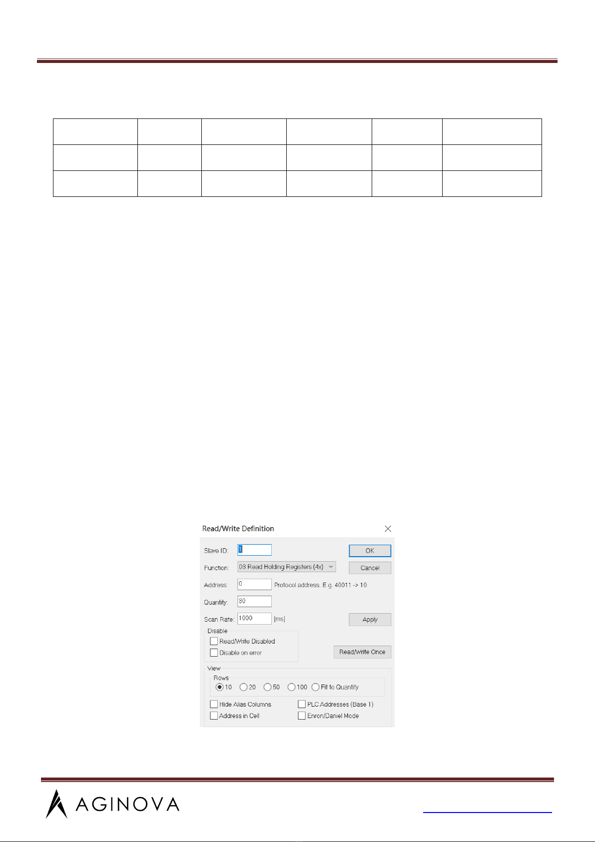
1、Click “Setup” on the menu bar, select “Read / Write Definition” and then set the parameters(The
slave address for the first time is the slave label), then enter “30” for Quantity in the dialog box , click
“OK”
Note: After the slave address is changed, the new address will be used for communication and the
slave address for the next time connection is also the most recently changed address.
Tel:+1 513 204 5837
Web:https://www.aginova.com
Sentinel (RS-485) DO • Operation Manual

8
2、Click “Connection” on the menu bar, select the first line in the drop-down menu “Connection
setup”(The baud rate for the first time is the slave label) and click “OK”.
Note: Port is set according to the Port number of the connection.
Note: If the sensor has been connected as described, and “Timeout Error” appears on the
software “Display status”, it means that the connection is failed; remove and replace the USB port
or check the USB to RS485 converter, repeat the above procedure until the sensor connection is
successful.
Chapter 5 Calibration of Sensor
The dissolved oxygen sensor has been calibrated at the factory and if you need to calibrate yourself,
follow the steps below
The specific steps of automatic air calibration are as follows:
Dry the sensor, add a small amount of water (25~50mL) to the calibration kit and shake the bag for a
few times. Then put the sensor into the calibration kit without touching the water and seal the
calibration kit with your hand to make the sensor in a saturated air. The sensor should be away from
light and high temperature and hard objects during calibration. The measured data is stable, Double-click
the “06”, and a dialog box pops out. Enter “27” for Address in the dialog box, “16” for Value, then click
“Send”.
Tel:+1 513 204 5837
Web:https://www.aginova.com
Sentinel (RS-485) DO • Operation Manual

9
Wait 20 seconds, change Value to “19” in the dialog box and click “Send”.
The specific steps of zero-point calibration are as follows:
Dry the sensor and place it in the anaerobic water until the measured data is stable, Double-click the
“06”, and a dialog box pops out. Enter “27” for Address in the dialog box, “12” for Value, then click
“Send”.
Wait 20 seconds, change Value to “19” in the dialog box and click “Send”.
Tel:+1 513 204 5837
Web:https://www.aginova.com
Sentinel (RS-485) DO • Operation Manual

10
Chapter 6 Communication Protocol
The sensor is equipped with MODBUS RS485 communication function, please refer to this
manual section 3.2 to check the communication wiring. The specific MODBUS RTU table is shown
in the following table.
MODBUS-RTU
Baud Rate 4800/9600/19200/38400/57600
Data Bits 8 bit
Parity Check no
Stop Bit 1bit
Register Name Address Data Type Register Number Read/Write Description
Dissolved Oxygen
Val ue
0 Float 2 R(only read)
Dissolved Oxygen
Concentration
2 Float 2 R
Temperature 4 Float 2 R
Slope 6 Float 2 W/R
Range:
0.5~1.5
Tel:+1 513 204 5837
Web:https://www.aginova.com
Sentinel (RS-485) DO • Operation Manual

11
Deviation Value 8 Float 2 W/R
Range:
-20~20
Salinity 10 Float 2 W/R
Atmospheric Pressure 12 Float 2 W/R
Baud Rate 16 Float 2 R
Slave Address 18 Float 2 R Range: 1~254
Response Time of
Read
20 Float 2 R
Modify Baud Rate 16 Signed 1 W
0-4800
1-9600
2-19200
3-38400
4-57600
Modify Slave Address 17 Signed 1 W Range: 1~254
Modify Response
Time
30 Signed 1 W
2~60s
(multiples of 2)
Air
Calibration
Step 1 27 Signed 1 W 16
Step 2 27 Signed 1 W 19
It should be cancelled if you don’t want to calibrate after the execution of “Step 1”.
Cancel 27 Signed 1 W 21
Zero-point
Calibration
Step 1 27 Signed 1 W 12
Step 2 27 Signed 1 W 19
It should be cancelled if you don’t want to calibrate after the execution of “Step 1”.
Cancel 27 Signed 1 W 21
Function Code
R:03
Write 06 as the reshaping data 06
Write 16 as the floating point data
485 analysis:
Tel:+1 513 204 5837
Web:https://www.aginova.com
Sentinel (RS-485) DO • Operation Manual

12
1、Read the slope
Register Name Address Data Type Register Number Read/Write Description
Slope 6 F 2 W/R Range:0.5-1.5
Send the command:01 03 00 06 00 02 24 0A
The equipment return:01 03 04 00 00 40 E0 CA 7B
Send command parsing:
01:device address 01
03:Function code 03 for reading register content
00 06:The starting register address read is 0006
00 02:Read 2 registers
24 0A:CRC16 check code
The device returns the analysis:
01:device address 01
03:Function code 03 for reading register content
04:The length of the returned data is 4 bytes
00 00 40 E0:The slope read is 7.00(analyze 40 E0 00 00 using IEEE 754)
CA 7B:CRC16 check code
2、Modify Slave Address
Register Name Address Data Type Register Number Read/Write Description
Modify Slave
Address
17 Signed 1 W Range: 1-254
Send the command: 01 06 00 11 00 0F 99 CB
The equipment return:01 06 00 11 00 0F 99 CB
Send command parsing:
01:device address 01
06:Function code 06 for writing register content
00 11:The register address of write data is 0017
00 0F:Write data content of 0015
Tel:+1 513 204 5837
Web:https://www.aginova.com
Sentinel (RS-485) DO • Operation Manual

13
99 CB:CRC16 check code
The device returns the analysis:
01:device address 01
06:Function code 06 for reading register content
00 11:The register address of the return write data is 0017
00 0F:Returns modified data content of 0017
99 CB:CRC16 check code
3、Set the slope
Register Name Address Data Type Register Number Read/Write Description
Slope 6 F 2 W/R Range:0.5-1.5
Send the command:01 10 00 06 00 02 04 00 00 3F 80 63 D5
The equipment return:01 10 00 06 00 02 A1 C9
Send command parsing:
01:device address 01
10:Function code 16 for writing register content
00 06:The starting register address write is 00 06
00 02:Write 2 registers
04:The length data is 4 bytes
00 00 3F 80:The slope write is 1.00(analyze 3F 80 00 00 using IEEE 754)
63 D5:CRC16 check code
The device returns the analysis:
01:device address 01
10:Function code 16 for writing register content
00 06:The starting register address of the return write data is 00 06
00 02:Returns 2 registers
A1 C9:CRC16 check code
Tel:+1 513 204 5837
Web:https://www.aginova.com
Sentinel (RS-485) DO • Operation Manual

14
Chapter 7 Maintenance
In order to obtain the best measurement results, it is very necessary to maintain the sensor regularly.
Maintenance mainly includes cleaning, inspecting damage of the sensor. You can also view the sensor’s
status during maintenance and inspection.
7.1 Sensor Cleaning
It is recommended that the sensor should be cleaned at regular intervals (usually 3 months,
depending on the site environment) to ensure the accuracy of the measurement.
Use water to clean the outer surface of the sensor. If there is still debris, wipe it with a damp soft
cloth. Do not place the sensor in a direct sunlight or near radiation. In the entire life of the sensor, if the
total sun exposure time reaches to one hour, it will cause the fluorescent cap aging and going wrong, and
consequently leading to the wrong reading.
7.2 Inspection on the Damage of Sensor
According to the appearance of sensor to check if there is damage; if any damage is found, please
contact after-sales service maintenance center in time for replacement to prevent malfunction of sensor
caused by water from the damaged cap.
7.3 Preservation of Sensor
A、When you are not using it, please cover the product’s original protective cap to avoid direct
sunlight or exposure. In order to protect the sensor from freezing, the DO probe should be stored in a
place where it will not freeze.
B、Keep the probe clean before storing it for a long time. Keep the equipment in a shipping box or a
plastic container with electric shock protection. Avoid touching it with hand or other hard objects in case
of scratching the fluorescent cap.
C、It is forbidden that the fluorescent cap is exposed to direct sunlight or exposure.
Tel:+1 513 204 5837
Web:https://www.aginova.com
Sentinel (RS-485) DO • Operation Manual

15
7.4 Replacement of Fluorescent Cap
The sensor's measurement cap needs to be replaced when it’s damaged. In order to ensure the
accuracy of the measurement, it is recommended to change it every year or it is necessary to be replaced
when the cap is found severely damaged during the inspection.
Steps to replace the fluorescent cap: Unscrew the old cap from the sensor, and then screw the
new cap on.
Note: When removing and installing fluorescent cap, pay attention to whether the sealing ring
is out of position. If there is a mismatch, it must be reassembled.
version number:R1010_200601
Tel:+1 513 204 5837
Web:https://www.aginova.com
Sentinel (RS-485) DO • Operation Manual
Table of contents
Other Aginova Accessories manuals


