5
the work or pull the saw backward while the blade is in motion or KICKBACK may occur.Investigate and
take corrective actions to eliminate the cause of blade binding.
C).When restarting a saw in the workpiece, center the saw blade in the kerf and check that teeth are not
engaged into the material. If saw blade is binding, it may walk up or KICKBACK from the workpiece as
the saw is restarted.
D).Support large panels to minimize the risk of blade pinching and KICKBACK. Large panels tend to sag
under their own weight. Supports must be placed under the panel on both sides, near the line of cut and
near the edge of the panel.Do not use dull or damaged blade. Dull blades produce a narrow kerf causing
excessive friction, blade binding, and KICKBACK.
F).Blade depth and bevel adjusting locking levers must be tight and secure before making cut. If blade
adjustment shifts while cutting, it may cause binding and kickback.
G).Use extra caution when sawing into existing walls or other blind areas. The protruding blade may cut
objects that can cause kickback.
11. Use only recommended blades, rated at the machine’s maximum rated RPM or higher with correct arbor
hole.
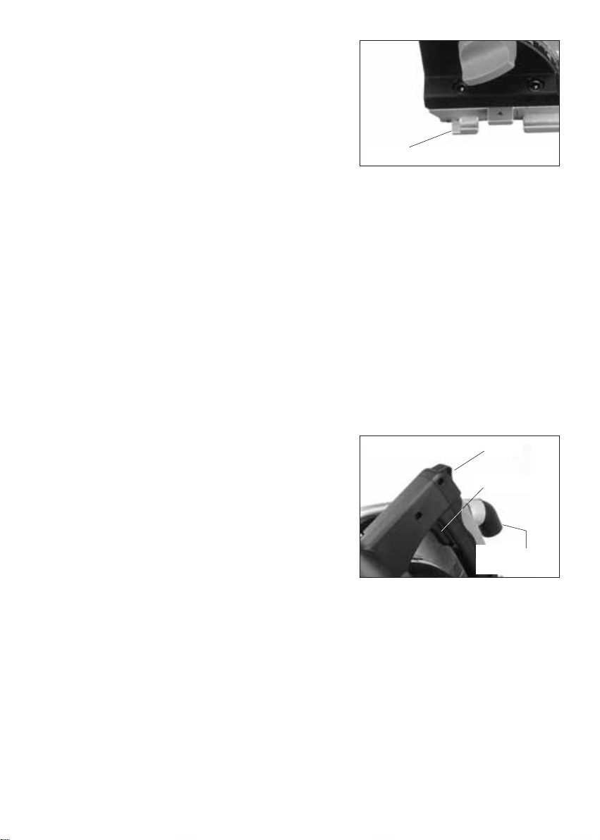
Guard function
a).Check guard for proper closing before each use. Do not operate the saw if guard does not move freely
and enclose the blade instantly. Never clamp or tie the guard so that the blade is exposed. If saw is
accidentally dropped, guard may be bent. Check to make sure that guard moves freely and does not touch
the blade or any other part, in all angles and depths of cut.
b).Check the operation and condition of the guard return spring. If the guard and the spring are not
operating properly, they must be serviced before use. Guard may operate sluggishly due to damaged parts,
gummy deposits, or a build-up of debris.
c).Assure that the base plate of the saw will not shift while performing the “plunge cut” when the blade
bevel setting is not at 90°. Blade shifting sideways will cause binding and likely kick back.
d).Always observe that the guard is covering the blade before placing saw down on bench or floor. An
unprotected, coasting blade will cause the saw to walk backwards, cutting whatever is in its path. Be aware
of the time it takes for the blade to stop after switch is released.
12. Tighten blade retaining bolt and all clamps before operating.
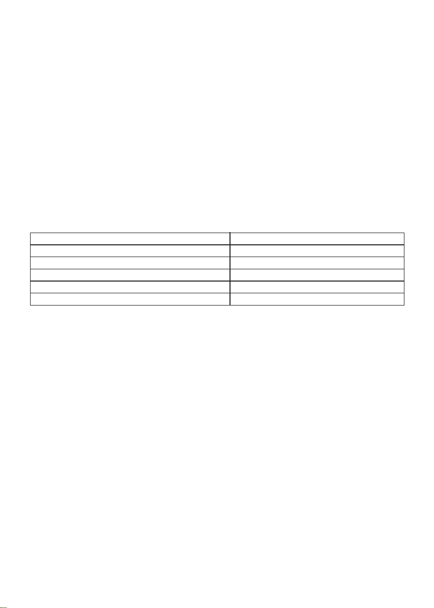
Riving knife function
a).Use the appropriate saw blade for the riving knife. For the riving knife to function, the body of the blade
must be thinner than the riving knife and the cutting width of the blade must be wider than the thickness of
the riving knife.
b).Adjust the riving knife as described in this instruction manual. Incorrect spacing, positioning and
alignment can make the riving knife ineffective in preventing kickback.
c).For the riving knife to work, it must be engaged in the workpiece. The riving knife is ineffective in
preventing kickback during short cuts.
d).Do not operate the saw if riving knife is bent. Even a light interference can slow the closing rate of a
guard.
13. Secure workpiece properly. Workpiece should be straight and firmly clamped to avoid possible movement
and pinching as the cut nears completion.
14. Allow the blade to come to a complete stop before removing or securing workpiece, or changing
workpiece angle.
15. Check the inside surfaces of the arbor flanges as well as the sides of the blade for freedom from any foreign