HULTDINS SuperSaw 550S User manual

DANGER SAW
6HUYLFHPDQXDO
61DQGXS
6XSHU6DZ6

2001– HULTDIN SYSTEM AB.
This publication contains instructions for the maintenance of the
6XSHU6DZ6
grapple saw units. The instructions cover
general information, procedures and specifications applicable to this grapple saw. If doubt should arise concerning the
validity of the instructions please consult the nearest dealer for more detailed information.
Illustrations, technical information and specifications were, as far as we have been able to judge, correct at the time of print.
However, we reserve the right to, without prior notice, revise specifications, instructions, equipment, etc. as a result of
ongoing product improvement activities.
No part of this publication may without approval of HULTDIN SYSTEM AB be translated, reproduced, stored or
transmitted electronically, mechanically, photographically or in another way not specified here.
Even if all conceivable measures have been taken to make the contents as complete as possible, HULTDIN SYSTEM AB
takes no responsibility for possible damages that may arise as a result of the instructions not being followed or improper use
of the product.
,PSRUWDQW
The parts and components used in HULTDIN SYSTEM AB’s products are specifically chosen. Therefore original
spare parts are always the best alternative in a possible need of repairs or upgrading.
All service and repairs should be carried out by qualified service personnel or an authorized repair shop with suitable tools
and lifting devices.
This publication is published by: HULTDIN SYSTEM AB
Skolgatan 12
SE-930 70 Malå
SWEDEN

en0100.ss550sTOC.fm
&217(176
&RQWHQWV 3DJH &RQWHQWV 3DJH
6DIHW\LQVWUXFWLRQV
.................................................... 5
Welding ................................................................ 6
Modifying the equipment..................................... 6
6\VWHPRYHUYLHZ
....................................................... 7
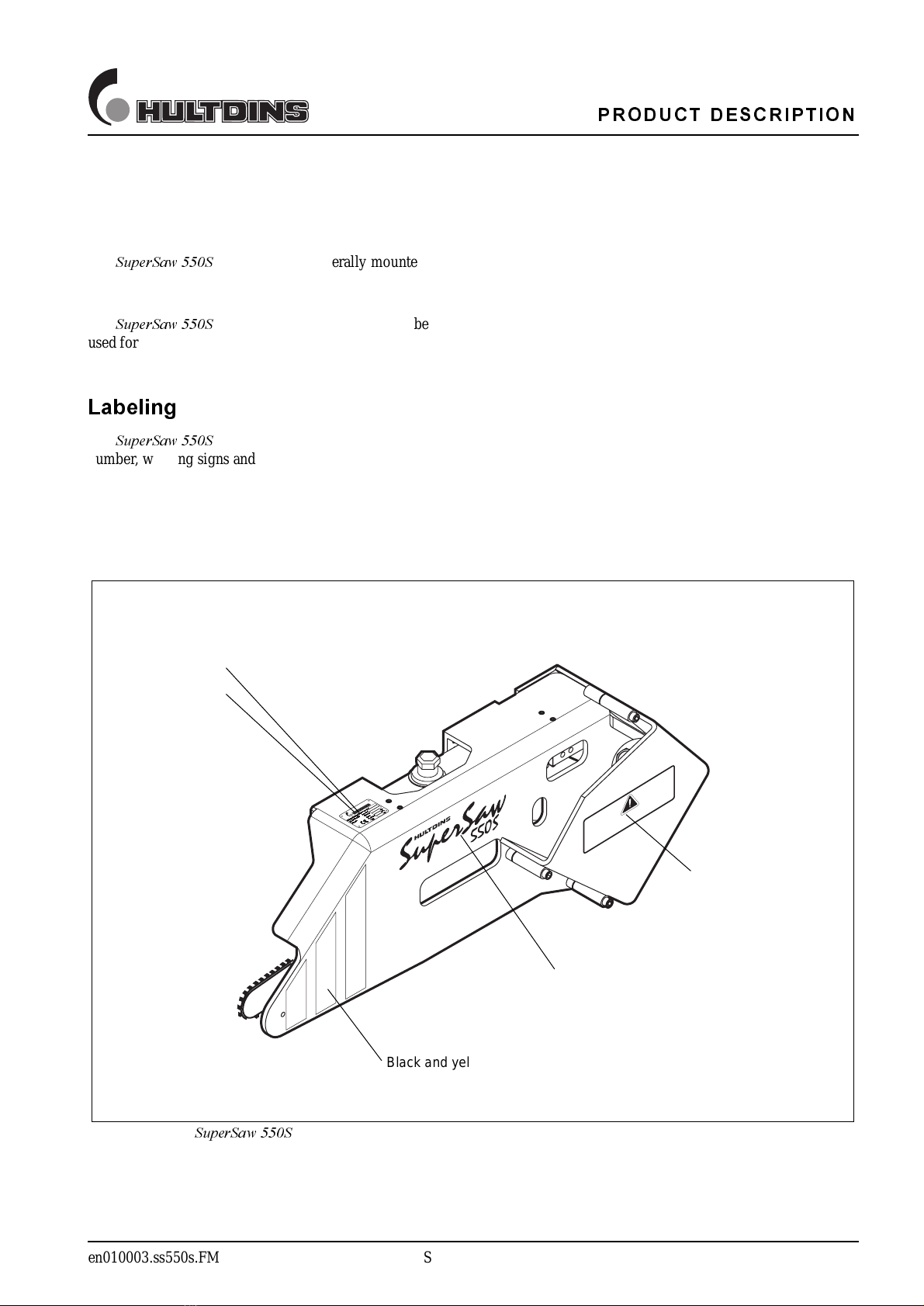
3URGXFWGHVFULSWLRQ
.................................................. 9
7HFKQLFDOGDWD
......................................................... 11
SuperSaw 550S / TL..................................... 11
SuperSaw 550S / SG .................................... 13
Special tools ....................................................... 15
Air Pump ...................................................... 15
Combi Wrench.............................................. 15
Standard tools..................................................... 16
Wrenches...................................................... 16
Allen keys..................................................... 16
Hydraulic Diagram SuperSaw 550S/TL ............ 17
Hydraulic Diagram SuperSaw 550S/SG............ 18
)XQFWLRQDOGHVFULSWLRQ
........................................... 19
Saw activated chain tensioning.......................... 19
Pressure line feed out system............................. 20
Lubrication system............................................. 21
$VVHPEO\DQG'LVDVVHPEO\
................................... 22
Installing the SuperSaw 550S on TL grapples... 22
Installing the SuperSaw 550S on SG grapples... 24
Adjusting chain tension pressure ....................... 27
Adjusting saw bar feed out pressure.................. 28
Adjusting saw bar retraction .............................. 29
Charging the air tank.................................... 29
Depressurizing the air tank........................... 30
Replacing Accumulator...................................... 31
Refilling lubrication oil tank.............................. 32
Bleeding chain tension system........................... 33
Saw activated tensioning.............................. 33
Constant pressure activated tensioning ........ 34
Bleeding chain lubrication system ..................... 34
Replacing saw chain........................................... 35
Replacing saw bar.............................................. 36
Replacing bar holder.......................................... 37
Manual chain tensioning.................................... 38
Replacing broken guide screw........................... 39
Replacing piston seals........................................ 40
Replacing piston rod seal................................... 41
Testing function of check valve ......................... 42
Replacing tension- and lub. oil hoses................. 42
0DLQWHQDQFHLQVWUXFWLRQV
...................................... 43
Regular maintenance.......................................... 43
Daily maintenance........................................ 43
Every 250 hours of operation....................... 43
Every year of operation................................ 43
Lubrication ................................................... 44
Fastener joints and hydraulic hoses.............. 44
The first month of operation .............................. 44
Fasteners....................................................... 44
7URXEOHVKRRWLQJ
...................................................... 45
SuperSaw 550S............................................. 45
SuperCut....................................................... 46

6$)(7<,16758&7,216
en019901.sc.FM Safety instructions 5
6DIHW\LQVWUXFWLRQV
This page describes important safety instructions, which
the operator’s of Hultdins SuperFell, SuperSaw and
SuperCut attachments should have a good knowledge of
before the equipment is used.
The service manual should be available at all times so that
the operator is able to follow safety regulations and the
procedures of maintenance activities..
1RWH
Read carefully and understand the following
information with concerns to safe operation practices
before operating this equipment.
,PSRUWDQW
The owner and the operator are responsible for
following all safety regulations and that the machine
is safely equipped.
,PSRUWDQW
Check the machine for damages at the beginning of
each shift.
,PSRUWDQW
Inspect and lubricate the unit atthe beginning of each
shift. Tighten all fasteners regularly.
,PSRUWDQW
All service and repairs should be carried out by
qualified personnel or an authorized repair shop with
suitable tools and lifting devices.
,PSRUWDQW
When working on the saw chain always ensure the
engine is shut off and wear safety gloves to prevent
injuries. Remove the saw chain when making any
adjustments or servicing the saw unit.
,PSRUWDQW
Never adjust any hydraulic pressures without using a
pressure gauge.
,PSRUWDQW
Consider the environment. Plug all connections to
avoid unnecessary spill of oil.
:DUQLQJ
The hydraulic input of the equipment must not
exceed the recommended maximum rating as
structural failure could occur, resulting in injury and
damaged equipment.
:DUQLQJ
Before performing any maintenance or service work,
lower the attachment to the ground and shut off the
engine. Turn off any master shut-offs and do not
allow personnel in the cab.
:DUQLQJ
Keep all windows and doors securly closed when
operating.
:DUQLQJ
Never touch or stand close to the pressurized
cylinders and hydraulic hoses.
:DUQLQJ
The attachment has sharp edges. Use proper
wrenches and protective gloves when working on the
attachment.
Fig. 1 The operating area of the saw attachment and the
recommended safety distance
90 meters/300 feet
:DUQLQJ
When operating this equipment ensure all other
personnel remain at least 300 feet clear of the
machine. Turn the machine off immediately if
anyone enters this safety zone.
:DUQLQJ
Training or demonstration of this equipment should
be performed from an operator´s cab approved by
national regulations. Observers should always
remain at least 300 feet away.
:DUQLQJ
Always use High Speed saw chains with 3/4” pitch
saw units.

6$)(7<,16758&7,216
6 Safety instructions en019901.sc.FM
:HOGLQJ
In case of a structural repair of the equipment, when
welding may be needed, consult the dealer for
recommended instructions.
:KHQZHOGLQJRQWKHDWWDFKPHQWWKHIROORZLQJVWHSV
PXVWEHWDNHQ
• Make sure that fire-extinguishing equipment is
available.
• Clean the area around the welding area to
eliminate any fire hazard.
• Connect the ground wire so the welding current
does not pass over any bushings.
• Place the ground wire as close to the welding area
as possible.
0RGLI\LQJWKHHTXLSPHQW
,WLVQRWDSSURYHGWR
• Modify the equipment without the consent of
HULTDIN SYSTEM AB.
• Alter the function of the equipment without the
consent of HULTDIN SYSTEM AB.
• Use spare parts other than original HULTDINS
parts.

6<67(029(59,(:
en010002.ss550s.FM SuperSaw 550S 7
6\VWHPRYHUYLHZ
The
6XSHU6DZ6
is made up of the following main
parts. All parts are replaceable.
1Frame
2 Lubrication oil tank
3 Filler cap
4 Pressure regulating valve
5 Saw unit
6 Saw motor with manifold
7 Accumulator for saw motor case drain
8 Saw motor cover
Fig. 2 System overview
DANGER SAW
13
2 5
4 6 7 8

6<67(029(59,(:
8 SuperCut 0703853/0703860 EN019802.0703853.FM
6\VWHPRYHUYLHZ
6XSHU&XW
The
6XSHU&XW
is made up of the
following main parts. All parts are replaceable.
1 Saw stand
2 Tensioning device
3 Bar holder
4 Feed out cylinder
5 Lubrication oil pump with cam curve
Fig. 3 System overview
1
2
3
4
5

352'8&7'(6&5,37,21
en010003.ss550s.FM SuperSaw 550S 9
3URGXFWGHVFULSWLRQ
The
6XSHU6DZ6
grapple saw is generally mounted
together with SuperGrip or SuperGrip TL grapples on log
loaders, excavators etc.
The
6XSHU6DZ6
grapple saw is only intended to be
used for timber, in whole-tree, tree length, and waste wood
systems.
/DEHOLQJ
The
6XSHU6DZ6
is labeled with a product sign, serial
number, warning signs and an identification sign
according to the following figure.
Fig. 4 Labeling
6XSHU6DZ6
DANGER SAW
Identification sign
Serial Number
Product sign
Warning sign
Black and yellow warning stripe

352'8&7'(6&5,37,21
10 SuperCut 0703853/0703860 EN019803.0703853.FM
3URGXFWGHVFULSWLRQ
6XSHU&XW
Together with its range of accessories, Hultdins patented
6XSHU&XW
saw unit is a comprehensive
alternative for all applications with demands on
functionality, reliability, service-friendliness, economy
and the environment.
6XSHU&XW
is a complete unit with
integrated feed cylinder, well protected from external
damage. It has been designed for use with hydraulic
motors of the type VOAC F11 - 10 or, alternatively, F11 -
19. The saw motor bracket is assembled in ballbearings in
the saw unit so that the hydraulic motor is stationary when
the saw is fed out. The saw bar is returned either
pneumatically by an accumulator or hydraulically with oil.
In its standard version, the
6XSHU&XW
is
equipped with automatic hydraulic chain tensioning and
cam controlled mechanical lubrication pump that
distributes lubricant to the chain during the complete
sawing operation.
The mechanical lubrication pump delivers a maximum
volume of 6 ml and the process can easily be adapted to
specific lubricating requirements with a number of
different cams. All the lubrication oils found on the market
can be used.
All this in combination gives good saw bar, chain and oil
economy.
With the accessories that are available for the
6XSHU&XW
, you can easily design an integrated
unit consisting of the saw unit, cam, saw motor, saw motor
manifold, pressure regulating valve kit and drive sprocket
kits.
Air and lubrication oil tanks are available as extra
accessories and the
6XSHU&XW
can be
equipped with a saw home detector sensor and a cut
control kit as options. The cut control kit is used in
combination with a computerized bucking device and
limits the angle to which the saw bar is fed out in
relationship to the diameter of the tree.
/DEHOLQJ
The
6XSHU&XW
is labeled with serial
number according to the following figure.
6HH)LJ
Fig. 5 Labeling
6XSHU&XW
Serial number

7(&+1,&$/'$7$
en010004a.ss550s.FM SuperSaw 550S 11
7HFKQLFDOGDWD
6XSHU6DZ67/
6XSHU6DZ67/
Saw motor displacement........... 1.16 cu.in. (19 cm3)
Weight ...................................... xxx lb. (xxx kg)
Weight with bracket.................. xxx lb. (xxx kg)
Length (A)................................. 45.47 in. (1155 mm)
Width (B).................................. 8.23 in. (209 mm)
Heigth (C)................................. 17.76 in. (451 mm)
Width (D).................................. 5.79 in. (147 mm)
Saw bar and chain..................... .404 pitch
Chain tension ............................ Automatic
Chain lubrication....................... Proportional
+\GUDXOLFSUHVVXUHVDQGIORZHV
Hydraulic pressure
( saw motor )............................. 16 - 31 MPa
(2300 - 4500 Psi)
Hydraulic flow
( saw motor )............................. 120 - 220 lpm
(31 - 58 GPM)
Hydraulic pressure
( chain tensioning ) ................... 2.0 - 2.5 MPa
(290 - 362 Psi)
Hydraulic pressure
( saw bar feed out) .................... 3.8 - 4.2 MPa
(550 - 610 Psi)
Air pressure
( saw bar retraction).................. 1.2 - 1.4 MPa
(175 - 200 Psi)
Gas pressure
( accumulator)........................... 0.1 MPa
(14.5 Psi)
Max. saw chain speed............... See recommendations
from each saw chain
manufacturer.
Max. power input to saw chain. See recommendations
from each saw chain
manufacturer.
Fig. 6 Dimensions
A
B
D
C

7(&+1,&$/'$7$
12 SuperSaw 550S en010004a.ss550s.FM
7RUTXHDQGVRFNHWZUHQFKVL]HV
+H[KHDG&DS6FUHZV 7RUTXH :UHQFKVL]H
M6S 5 8.8 ................ 4.3 FT.LB. (5.7 Nm) 8 mm
M6S 6 8.8 ................ 7.4 FT.LB. (9.8 Nm) 10 mm
M6S 12 8.8 ................ 61 FT.LB. (81 Nm) 18 mm
M6S 20 8.8 ................ 406 FT.LB. (541 Nm) 30 mm
6RFNHWKHDG&DS6FUHZV 7RUTXH 6RFNHWVL]H
MC6S 5 12.9 .............. 7.3 FT.LB. (9.7 Nm) 4 mm
MC6S 6 12.9 .............. 12.8 FT.LB. (17 Nm) 5 mm
MC6S 8 12.9 .............. 30 FT.LB. (40 Nm) 6 mm
MC6S 10 12.9 .............. 59 FT.LB. (79 Nm) 8 mm
MC6S 12 12.9 .............. 102 FT.LB. (136 Nm) 10 mm
MC6S 16 12.9 .............. 250 FT.LB. (333 Nm) 14 mm
MC6S 20 12.9 .............. 487 FT.LB. (649 Nm) 17 mm
1XWV 7RUTXH :UHQFKVL]H
M6M 16 24 mm
M6M 20 Loc-king 30 mm
*UHDVHDQG/RFWLWH
Grease Use a water free grease with lithium, molybdenum or silicone additive. The abilities of
the grease should include excellent water durability and antirust capabilities as well as
good adhesive abilities and mechanical stability. NLGI Class 2.
Thread sealant Loc-Tite 270
*UHDVLQJLQWHUYDOV
Every 8 to 200 hours of operation depending on the conditions that the unit is working under.

7(&+1,&$/'$7$
en010004b.ss550s.FM SuperSaw 550S 13
7HFKQLFDOGDWD
6XSHU6DZ66*
6XSHU6DZ66*
Saw motor displacement........... 1.16 cu.in. (19 cm3)
Weight ...................................... xxx lb. (xxx kg)
Weight with bracket.................. xxx lb. (xxx kg)
Length (A)................................. 45.47 in. (1155 mm)
Width (B).................................. 14.53 in. (369 mm)
Heigth (C)................................. 17.76 in. (451 mm)
Width (D).................................. 5.79 in. (147 mm)
Saw bar and chain..................... .404 pitch
Chain tension ............................ Automatic
Chain lubrication....................... Proportional
+\GUDXOLFSUHVVXUHVDQGIORZHV
Hydraulic pressure
( saw motor )............................. 16 - 31 MPa
(2300 - 4500 Psi)
Hydraulic flow
( saw motor )............................. 120 - 220 lpm
(31 - 58 GPM)
Hydraulic pressure
( chain tensioning ) ................... 2.0 - 2.5 MPa
(290 - 362 Psi)
Hydraulic pressure
( saw bar feed out) .................... 3.8 - 4.2 MPa
(550 - 610 Psi)
Air pressure
( saw bar retraction).................. 1.2 - 1.4 MPa
(175 - 200 Psi)
Gas pressure
( accumulator)........................... 0.1 MPa
(14.5 Psi)
Max. saw chain speed............... See recommendations
from each saw chain
manufacturer.
Max. power input to saw chain. See recommendations
from each saw chain
manufacturer.
Fig. 7 Dimensions
B
A
D
C

7(&+1,&$/'$7$
14 SuperSaw 550S en010004b.ss550s.FM
7RUTXHDQGVRFNHWZUHQFKVL]HV
+H[KHDG&DS6FUHZV 7RUTXH :UHQFKVL]H
M6S 5 8.8 ................ 4.3 FT.LB. (5.7 Nm) 8 mm
M6S 6 8.8 ................ 7.4 FT.LB. (9.8 Nm) 10 mm
M6S 12 8.8 ................ 61 FT.LB. (81 Nm) 18 mm
M6S 20 8.8 ................ 406 FT.LB. (541 Nm) 30 mm
6RFNHWKHDG&DS6FUHZV 7RUTXH 6RFNHWVL]H
MC6S 5 12.9 .............. 7.3 FT.LB. (9.7 Nm) 4 mm
MC6S 6 12.9 .............. 12.8 FT.LB. (17 Nm) 5 mm
MC6S 8 12.9 .............. 30 FT.LB. (40 Nm) 6 mm
MC6S 10 12.9 .............. 59 FT.LB. (79 Nm) 8 mm
MC6S 12 12.9 .............. 102 FT.LB. (136 Nm) 10 mm
MC6S 16 12.9 .............. 250 FT.LB. (333 Nm) 14 mm
MC6S 20 12.9 .............. 487 FT.LB. (649 Nm) 17 mm
1XWV 7RUTXH :UHQFKVL]H
M6M 16 24 mm
M6M 20 Loc-king 30 mm
*UHDVHDQG/RFWLWH
Grease Use a water free grease with lithium, molybdenum or silicone additive. The abilities of
the grease should include excellent water durability and antirust capabilities as well as
good adhesive abilities and mechanical stability. NLGI Class 2.
Thread sealant Loc-Tite 270
*UHDVLQJLQWHUYDOV
Every 8 to 200 hours of operation depending on the conditions that the unit is working under.

7(&+1,&$/'$7$
en010004c.ss550s.FM SuperSaw 550S 15
7HFKQLFDOGDWD
6SHFLDOWRROV
The following special tools are required when servicing
the SuperSaw 550S grapple saw.
$LU3XPS
The air pump is required when charging the air tank for the
saw bar retraction.
6HH)LJ
&RPEL:UHQFK
The combi wrench has two wrench sizes, 16mm and 7mm.
6HH)LJ
Fig. 8 Air Pump, P/N 0138042
Fig. 9 Combi wrench, P/N 0704040

7(&+1,&$/'$7$
en010004d.ss550s.FM SuperSaw 550S 17
7HFKQLFDOGDWD
+\GUDXOLF'LDJUDP6XSHU6DZ67/
Chain Tension Device
Saw Motor Manifold
Air Tank for saw bar return
Pressure Regulating Valve - chain tensioning
Dump Valve *
Saw Motor
Main Valve for Rotator, Grapple and Saw/Tilt*
Feed Out Cylinder
Grapple Cylinder
Restrictor
Rotator
Accumulator for drain circuit
Check Valves
Check Valve for chain tensioning
Pressure Regulating Valve - saw bar feed out
Pressure Test Point
* Required on carrier, but not supplied with the grapple saw.
Fig. 10 Hydraulic Diagram SuperSaw 550S / TL
Grapple Saw
Carrier
Carrier
Grapple Saw
19 MPa
2750 PSI 19 MPa
2750 PSI 20 MPa
2900 PSI
20 MPa
2900 PSI
0.1MPa
14.5 PSI
2.0 - 2.5MPa
290 - 362 PSI
PT
1.4MPa
200 PSI
25 MPa
3625 PSI
Alt. for closed centre.
ø2mm
7
9
11
3 8
16
10
15
13
13
12
13
6
16
14
4
1
5
7
2
5

7(&+1,&$/'$7$
18 SuperSaw 550S en010004e.ss550s.FM
7HFKQLFDOGDWD
+\GUDXOLF'LDJUDP6XSHU6DZ66*
Chain Tension Device
Saw Motor Manifold
Air Tank for saw bar return
Pressure Regulating Valve - chain tensioning
Dump Valve *
Saw Motor
Main Valve for Rotator, Grapple and Saw/Tilt*
Feed Out Cylinder
Grapple Cylinder
Restrictor
Rotator
Accumulator for drain circuit
Check Valves
Check Valve for chain tensioning
Pressure Regulating Valve - saw bar feed out
Pressure Test Point
* Required on carrier, but not supplied with the grapple saw.
Fig. 11 Hydraulic Diagram SuperSaw 550S / SG
Grapple Saw
Carrier
Carrier
Grapple Saw
PT
1.4MPa
200 PSI
2.0 - 2.5MPa
290 - 362 PSI
0.1MPa
14.5 PSI
ø2mm
19 MPa
2750 PSI 19 MPa
2750 PSI 20 MPa
2900 PSI
20 MPa
2900 PSI
25 MPa
3625 PSI Alt. for closed centre.
25 MPa
3625 PSI
9
11
3 8
16
10
15
13
13
12
6
16
14
4
1
5
7
2
7
5

)81&7,21$/'(6&5,37,21
en010005a.sc.FM Functional description 19
)XQFWLRQDOGHVFULSWLRQ
6DZDFWLYDWHGFKDLQWHQVLRQLQJ
When the feed line (P) is pressurised from the saw
function, a reduced pressure (2.0-2.5 MPa/290-360 PSI )
from the pressure regulating valve (3) acts on the pistons
(1) and (2). The piston (1) keeps the chain tight while the
pistons (2) hold the bar holder to the tensioning device
when sawing is in process. The spring (4) delivers
auxiliary tension during the first sawing operation after
replacing the chain. The check valve (5) prevents the chain
from becoming slack from external obstructions e.g.
undergrowth Fig. 12 Saw activated tensioning
1 Piston
2 Piston
3 Pressure regulating valve
4Spring
5 Check valve
2.0 - 2.5MPa
290 - 362 PSI
P
T
2
1
3 4
5

)81&7,21$/'(6&5,37,21
20 Functional description en010005d.sc.FM
)XQFWLRQDOGHVFULSWLRQ
3UHVVXUHOLQHIHHGRXWV\VWHP
When the saw motor feed line(2) is pressurised, a reduced
pressure / flow will be created in the pressure regulating
valve(6) and restrictor(5).
6HH)LJ
Fig. 13 Pressure line feed out system
1 Feed out cylinder
2 Saw motor pressure line
3Sawmotor
4 Saw motor return line
5 Restrictor for feed out speed
6 Pressure regulating valve for feed out pressure
PT
1
3
2 4
5
6
This manual suits for next models
1
Other HULTDINS Saw manuals
Popular Saw manuals by other brands

Kraftixx
Kraftixx TKS 254/2000 Original operating instructions

Makita
Makita JR3051TK instruction manual

Chicago Electric
Chicago Electric 98265 Set up and operating instructions

Scheppach
Scheppach HM80MP Translation from the original instruction manual

Logosol
Logosol M7 owner's manual

Ryobi
Ryobi RCS18X manual