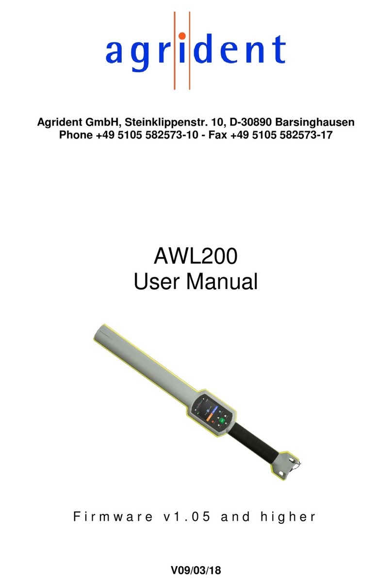
Agrident AWR 100 User manual

Agrident GmbH, Steinklippenstr. 11, D-30890 Barsinghausen
Phone +49 5105 582573-10 - Fax +49 5105 582573-17
AWR 100
Stickreader
Firmware 2.00 and higher
PC-Demosoftware 2.00 and higher
V10/02/10

10/02/10 Page 2 of 48
AWR100 Manual
© Copyright 2010 by Agrident GmbH
Torsten Bade, Technical Support
All rights reserved. No part of this publication may be reproduced, stored in a retrieval system,
or transmitted, in any form or by any means, electronic, mechanical, photocopying, recording or
otherwise, without prior written permission of Agrident GmbH.
Agrident GmbH reserves the right to make changes to any and all parts of this documentation
without obligation to notify any person or entity of such changes.
February 2010
Agrident GmbH
Steinklippenstr. 11
30890 Barsinghausen
Germany
Phone +49 (0) 51 05 582573-10
Fax +49 (0) 51 05 582573-17
www.agrident.com

10/02/10 Page 3 of 48
AWR100 Manual
Content
1Typical applications ............................................................................................. 5
2Preparing for use................................................................................................. 6
2.1 AWR signaling and interface ........................................................................ 7
2.2 Accessories.................................................................................................. 8
2.3 Installing or changing the battery pack ......................................................... 9
3Trickle charging the battery pack....................................................................... 11
4Battery pack fast charger .................................................................................. 12
5Controlling the AWR.......................................................................................... 13
5.1 Switching on the AWR................................................................................ 13
5.2 Reading transponders ................................................................................ 14
5.2.1 Reading transponders after the AWR is switched on .......................... 14
5.2.2 Reading transponders immediately..................................................... 17
5.3 Reading range depending on the transponder orientation ......................... 17
5.4 Using the AWR menu................................................................................. 18
5.4.1 Next group........................................................................................... 19
5.4.2 Printer ................................................................................................. 19
5.4.3 Stored datasets ................................................................................... 19
5.4.4 Show last IDs ...................................................................................... 20
5.4.5 Date/Time............................................................................................ 21
5.4.6 Online / offline mode .......................................................................... 21
5.4.7 Bluetooth............................................................................................. 21
5.4.8 Start Inquiry......................................................................................... 22
5.4.9 Custom config ..................................................................................... 23
5.4.10 Reset config ........................................................................................ 23
5.4.11 Clear datasets ..................................................................................... 24
5.5 High power mode ....................................................................................... 24
5.6 Permanent Read ........................................................................................ 24
5.7 Switch off time............................................................................................ 25
5.8 Show Tag time ........................................................................................... 25
5.9 Battery management .................................................................................. 25
6AWR100 Demo Software .................................................................................. 26
6.1 Installation .................................................................................................. 26
6.2 Comport settings ........................................................................................ 26
6.3 The file menu ............................................................................................. 27

10/02/10 Page 4 of 48
AWR100 Manual
6.4 The monitor window ................................................................................... 28
6.5 Diagnosis ................................................................................................... 28
6.6 Database.................................................................................................... 28
6.6.1 Database – Main ................................................................................. 29
6.6.2 Dataset – Amount of datasets............................................................. 30
6.6.3 Database – Dataset ............................................................................ 30
6.6.4 Database – File ................................................................................... 30
6.6.5 Database – Separation ....................................................................... 31
6.7 Event Database.......................................................................................... 31
6.8 Received Tag ............................................................................................. 33
6.9 Configuration.............................................................................................. 33
6.9.1 Configuration – Reader ....................................................................... 35
6.9.1.1 Serial number - Firmware................................................................ 35
6.9.1.2 Access level .................................................................................... 35
6.9.1.3 Extra Settings - Timeouts ................................................................ 35
6.9.1.4 LCD – Second Display Line............................................................. 36
6.9.1.5 LCD - Contrast ................................................................................ 37
6.9.1.6 LCD – Display Menu Language....................................................... 37
6.9.2 Configuration – Operational ................................................................ 38
6.9.2.1 IO – Led and Beeper ....................................................................... 38
6.9.2.2 RF – Power Mode ........................................................................... 38
6.9.2.3 Check for double-reads ................................................................... 39
6.9.2.4 Permanent Read ............................................................................. 39
6.9.2.5 Wireless Synchronization ................................................................ 40
6.9.3 Configuration – Output Formats .......................................................... 42
6.9.4 Configuration – Bluetooth.................................................................... 43
6.9.5 Configuration – Printer ........................................................................ 44
6.9.6 Configuration – Real Time Clock......................................................... 45
6.9.7 Configuration – Memory...................................................................... 45
7Safety and care ................................................................................................. 46
8Warranty............................................................................................................ 46
9FCC digital device limitations ............................................................................ 47
10 Canadian Radio Emissions Requirement ...................................................... 47
11 CE MARKING ................................................................................................ 47
11. Trouble shooting ............................................................................................ 48

10/02/10 Page 5 of 48
AWR100 Manual
1 Typical applications
Downloading the collected data via RS232
(or USB using an RS232-USB converter)
Bi-directional communication with PDA via Bluetooth
Transmitting the transponder number
to RFID ready scales via RS232…
…or Bluetooth
Printing the last group or the complete
memory content via RS232…
…or via Bluetooth

10/02/10 Page 6 of 48
AWR100 Manual
2 Preparing for use
Figure 1: AWR100 Stickreader
The AWR100 Stickreader is shipped with one rechargeable battery pack, one
RS232 end cap plus RS232 cable (1,5m), one power supply for trickle charging
and a CD containing all manuals and AWR100 demo software.
Before starting to work with the reader, it is recommended to charge the battery
pack completely. This can be done by using the power supply for trickle
charging (takes up to 20 hours) or the external fast-charging station (please see
chapters 2 and 3 for details).
When charging for the first time after long-term storage, the battery
capacity might be decreased. Restore such batteries to original
performance by repeating several cycles of charging and
discharging.
When storing batteries for more than 1 year, charge after 6 month to
prevent leakage and deterioration in performance due to self-
discharging.
antenna
RS232 cable
battery pack
button
handle grip
beeper
display
blue LED
end cap with RS232 and power interface
red and green LED
protection cap
hand strap

10/02/10 Page 7 of 48
AWR100 Manual
2.1 AWR signaling and interface
Parameter
Setting
Red LED
The red LED is flashing while the AWR tries to read
transponders. This feature can be disabled or enabled
with AWR demo software.
Green LED
The Green LED is flashing after a transponder was read.
This feature can be disabled or enabled with AWR demo
software.
Beeper
The Beeper sounds, after a transponder was read. This
option can be changed using the AWR demo software.
Blue LED
The blue LED is used for several events (e.g.
transponder was read, low battery warning).
Display
The LCD displays all necessary information (e.g.
number of read transponder, ready to work, menu
items).
Read button
is switching the reader on.
starts reading.
enters the menu by double pressing, if the AWR
is switched on
moves to the next menu item by a short press
confirms selections in the menu by a long press
Cable connector
Interface for transferring data between AWR and
other devices
Trickle charging the battery via RS232 cable

10/02/10 Page 8 of 48
AWR100 Manual
2.2 Accessories
Bluetooth end cap
External fast-charging station
Rechargeable battery pack
RS232 end cap
RS232 cable (1.5m)
Cigarette lighter cable (12V, for trickle charging only)
Figure 2: Accessories
Figure 3: External fast charging station
The power supply can vary country-specific.
end cap with RS232
and power interface
A
EC100
rechargeable battery
pack ARB100
Bluetooth end cap
A
BE1
00
RS232 cable
A
I
C
11
5
cigarette lighter
charging cable
AAC100

10/02/10 Page 9 of 48
AWR100 Manual
2.3 Installing or changing the battery pack
If the Stick Reader is used for the first time, the battery pack has to be installed.
Turn the screw of the end cap anti clockwise.
Remove the end cap.
Remove the old battery pack.

10/02/10 Page 10 of 48
AWR100 Manual
Install the new battery pack.
Attach the end cap to the reader and turn the screw of the end cap clockwise.
The screw has to be fastened completely, otherwise contact
problems can occur! Additionally the seal in the end cap is not
functioning properly in that case and the AWR might not be
watertight (IP67) anymore. Water damages due to the improper
attachment of the end cap are not covered by the warranty!

10/02/10 Page 11 of 48
AWR100 Manual
3 Trickle charging the battery pack
Trickle charging can take up to 20 hours, depending on the remaining battery
capacity. Longer charging is always allowed and does not damage the reader or
the battery.
Connect the RS232 cable to the RS232 end cap.
Plug in the RS232 connector into the jack of the RS232 end cap and turn the
connector clockwise.
From the point, where the green indicator ring appears, the connection of the
plug is correct and IP67.

10/02/10 Page 12 of 48
AWR100 Manual
Connect the power jack of the RS232 cable to the power supply for trickle
charging. Also connect the power supply to the mains using the power cord.
Figure 4: Connections and accessories for trickle charging
The power cord can vary country-specific.
4 Battery pack fast charger
For faster battery charging, an external charging station is available.
Figure 5: Battery pack fast charger, the power supply can vary country-specific.
power supply for trickle charging
RS232 cable
RS232 end cap
(attached to AWR)
power cord

10/02/10 Page 13 of 48
AWR100 Manual
Figure 6: Battery pack fast charger with battery pack inserted
5 Controlling the AWR
5.1 Switching on the AWR
In the off state, most parts of the electronic is separated from the battery. Only a
few parts (e.g. the internal Real Time Clock) are supplied with power. Nothing is
displayed on the LCD in that case. In order to activate the AWR, the button
must be pressed for a short time.
“Press key” appears on the first display line and a battery symbol on the right
side indicates the approximate remaining battery capacity.
Figure 7: Activate the AWR by pressing the read button
battery symbol

10/02/10 Page 14 of 48
AWR100 Manual
After the AWR is ready to work, the following text appears on the display:
Press key
If no action happens, the AWR will power down after a certain time. This time is
configurable from 5 seconds to 600 seconds, the default value is 10 seconds.
If Bluetooth is activated and connected, a Bluetooth symbol appears on the right
side of the second line of the display:
Press key
If a Bluetooth end cap is attached, the Bluetooth module is initialized after
switching on. It can take a few seconds until the Bluetooth connection is
established. Nevertheless the reader can start working and is able to read tags,
the connection is made in the background. The reader remembers the IDs of
the tags, which were read after switching on. As soon as the Bluetooth
connection is established, the AWR will send all these IDs to the Bluetooth
interface in case that the Online mode is activated.
5.2 Reading transponders
5.2.1 Reading transponders after the AWR is switched on
Wait until
Press key
appears on the display.
Press the button until
Read tag
.
appears on the LCD. Now release the button.
The AWR starts to read transponders for a certain time, which is also
configurable (see chapter 6.9.1.3 “Extra Settings - Timeouts”). The reading
procedure is signaled by a red flashing LED. Furthermore a progress bar
appears in the second line of the display. The flashing of the red LED can
enabled and disabled with the configuration software.

10/02/10 Page 15 of 48
AWR100 Manual
Figure 8: Reading Transponders

10/02/10 Page 16 of 48
AWR100 Manual
If no transponder has been read, the following message appears on the first line
of the LCD:
No Transponder
While displaying this message, the backlight of the display is on. If a
transponder has been read, the reading procedure is aborted immediately. A
successful reading is signaled by a green flashing LED at the top of the AWR, a
flashing blue LED above the display, and the beeper. The green LED and the
beeper can be enabled and disabled using the demosoftware.
In the first line of the LCD, the transponder number is displayed in decimal
format. The second line is used to show the reading time and the transponder
type, where “F” stands for FDX-B and “H” means HDX.
984 010900316360
F 12:41:26
The information in the second line can be changed for displaying an animal
counter or the advanced ISO information of the transponder. Please see
chapter 6.9.1.4 for further information.
The maximum time in which this information is displayed, is configurable as well
(Show Tag Time). This time can be configured from 1 second to 60 seconds,
the default value is 5. For further information please see chapter 6.9.1.3)
If an event is assigned to the read transponder via an external database, the
corresponding string will be displayed in the second line of the LCD:
Selection
Press Key
The maximum time in which the event string is displayed, is also configured via
the “Show Tag Time”. Pressing the button will exit this screen before the time
has elapsed. Chapter 6.7 explains the event-feature more detailed.
If no event is assigned to this transponder, the ID will be displayed according to
the configured time. After this time, or if the button was pressed before, the start
screen appears again:
Press key

10/02/10 Page 17 of 48
AWR100 Manual
5.2.2 Reading transponders immediately
If the AWR is switched off, press the button until
Read tag
.
appears on the display.
The reading procedure is the same as explained in chapter 5.2.1.
5.3 Reading range depending on the transponder orientation
Ferrite antennas have the following characteristics of flux lines:
Figure 9: Flux lines
Thus the following best reading orientation for transponders is:
Figure 10: Best reading orientation

10/02/10 Page 18 of 48
AWR100 Manual
Accordingly there are is also a worst reading orientation:
Figure 11: Worst reading orientation
5.4 Using the AWR menu
After the message
Press key
appears on the display, the menu of the reader can be entered by double
pressing the button. With a short-press you can move to the next menu item. A
long-press enters a submenu or confirms a selection within the corresponding
menu. If the button is not pressed within 3 seconds, the menu will be left auto-
matically.
The AWR menu has the following structure:
Menu item Complete
Access
Medium Access Read only
Next group
Printer * *
Stored datasets
Show last IDs
Date / Time
Online mode
Bluetooth on **
Start Inquiry **
Custom config *** ***
Reset config
Clear datasets **** ****
* only available if the printer option is enabled, default = disabled
** only visible if a Bluetooth end cap is attached to the AWR
*** only available if a custom configuration has been set via the demosoftware first
**** the checkbox “Clear Datasets” needs to be activated in addition to the Access level

10/02/10 Page 19 of 48
AWR100 Manual
The menu access level can be set via the AWR demosoftware (see chapter
6.9.1.2). The “Complete Access” level (factory default) shows all menu items, as
far as available. If, for example, no Bluetooth end cap is attached to the reader,
the Bluetooth options will not be displayed. The “Medium Access” level allows to
enter the menu and to access all features, which do not change the
configuration (except custom configuration). In these two modes it is possible,
to activate the additional option “Clear datasets”.
Please exercise extreme caution with the “Clear datasets” option!
This menu item allows to clear the complete memory content and
thus important data might get lost irreversibly!
The “Read only” setting ensures that the menu cannot be accessed at all.
5.4.1 Next group
The “Next group” option allows to insert separators between the collected IDs
and thus to divide the read transponders into groups. This is a helpful feature if,
for example, the data are collected on different farms or the animals are sold to
different places.
Agrident V2.00
->Next group
Perform a long press in order to insert a new group. After the group was created
successfully, you will see the following confirmation:
Agrident V2.00
Done
In addition the blue LED is switched on for appr. 1 second.
5.4.2 Printer
The printer menu is only visible, if the printer option is enabled, per factory
default it is disabled. You can change this setting using the AWR demo-
software. For further details about the printer option, please see the separate
manual “AWR_printer_option”.
5.4.3 Stored datasets
The next menu item shows the number of stored datasets:
Stored datasets
5/ 138/5000

10/02/10 Page 20 of 48
AWR100 Manual
The first number shows the animal counter of the current group, in this example
5. The second number represents the sum of all stored datasets including group
separators (in this example 138). The last number represents the amount of
datasets which can be stored on the AWR (5000).
The readers memory allows to store 5000 datasets. If 5000
transponders and separators were stored, the datasets must be
cleared before new transponders can be read.
In case that 5000 datasets are already stored and a new transponder is read,
the following information appears on the LCD display:
Database
out of memory
5.4.4 Show last IDs
This item allows you to review the complete memory content of the AWR.
Agrident V2.00
-> Show last IDs
Make a long-press while “Show last IDs” is displayed.
984 010900316360
G05#033 12:41:26
The first line of the displays shows the ID, the second line the group, in which
the ID is saved (here: group 5), the consecutive number of the dataset in the
current group (here: 33) and the timestamp of the transponder. The AWR starts
with the latest read ID and then goes through the memory backwards.
Perform a short press in order to move to the previous dataset, perform a long
press in order to move to the previous group. If the last transponder in the
group has been displayed, the reader will automatically move to the previous
group after a short-press:
Previous group
Group 0004
If you scrolled through the complete content of the memory, the display will
show:
Agrident V2.00
No IDs available
Other manuals for AWR 100
1
Table of contents
Other Agrident Card Reader manuals