6© Agrowtek Inc. | www.agrowtek.com
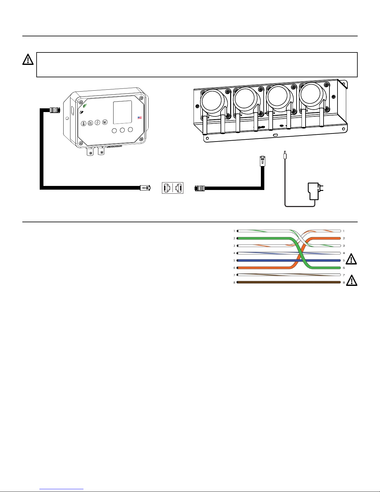
SXHM models with the optional
3-button/LCD display interface may
be used for stand-alone monitoring
applications or as part of a control
solution.
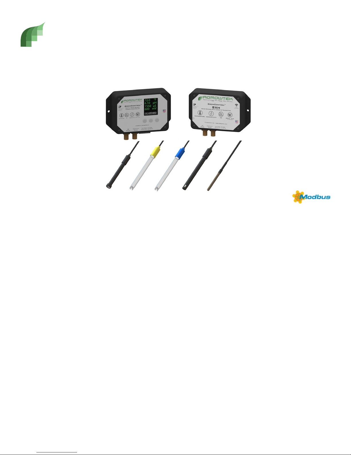
Connect to Agrowtek’s GrowControl
facility control systems, or directly to
Agrowtek’s AgrowDose pumps for
automatic nutrient and pH control.
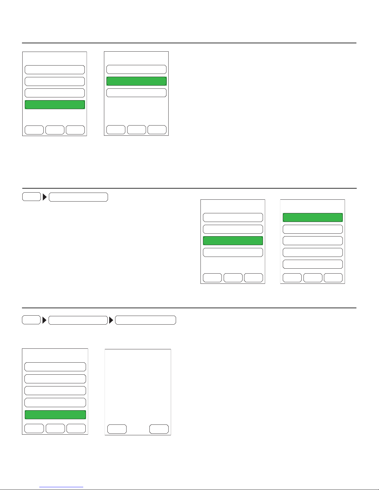
LCD Menu Operation Instructions
Simple minimum and maximum recorded values are stored until the user resets
the values to the current readings. To view the minimum and maximum values
since the last reset, press the button labeled H/L.
To clear the min/max history, press the RST button to reset. The min and max
values will all be set to the current readings and will update with higher or lower
readings as they occur.
High / Low History
GPH MNUH/L
72.0
6.10
1550
600
°F
pH
uS
mV
The main screen displays the real-time sensor readings from the attached sensors. Each button is labeled at
the bottom of the display to describe it’s function on the current screen or menu.
RSTEXIT
72.0
4.85
657
480
°F
pH
mV
68.4
4.21
551
404
uS
Technology to Help You Grow
AGROWtEK
U.S.A.
MADE IN
© Arowtek Inc. | www.agrowtek.com
GrowNET
Link Port
MODBUS
TM Digital Water Sensor
Logger & Controller
TEMPERATURE CONDUCTIVITYpH O.R.P. / D.O.
GrowControl
TM
pH
Probe
o.r.p./d.o.
Probe
Temp Probe | EC Probe
red blk wht | clr red blk
GPH MNUH/L
72.0
6.21
550
°F
pH
uS
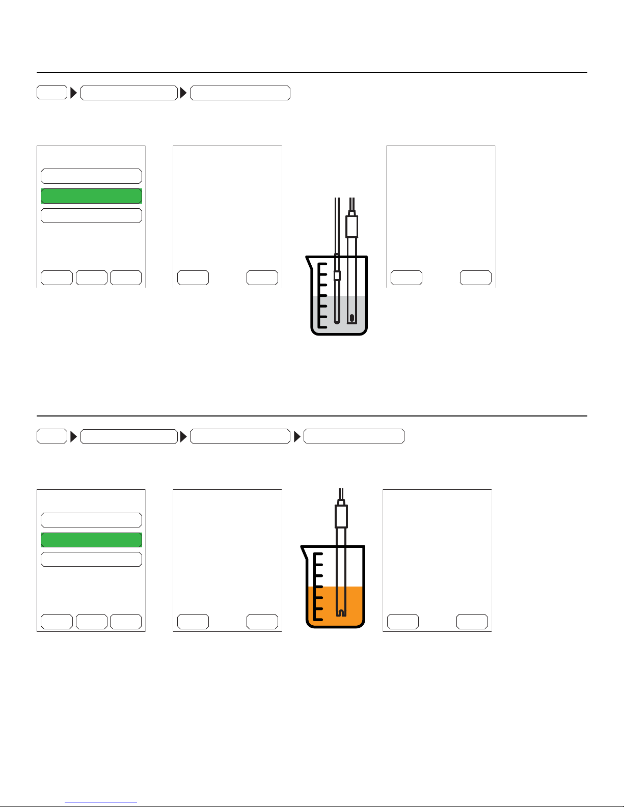
The display can graph the most recent 120
data points from the sensor’s internal data
point memory. With the default logging
interval of 60 seconds, the graph displays
the last two hours of data.
The sensor value is plotted in green. Tem-
perature, if overlaid on the plot, is red.
Alarm levels as set by the user are plotted in
yellow. Pressing the RFH button refreshes
the data and replots the graph.
Graphing
RFH BCK
PH
High Alarm
Low Alarm
Temperature
Sensor Data (pH)
GPH
MNUH/L
72.0
6.10
1550
600
°F
pH
uS
mV
DWN ENTUP
BACK
TEMPERATURE
PH
COND
GRAPH
ORP