AGT AGT-PD680-PZ User manual

sales@agrotkindustrial.com https://www.agrotkindustrial.com /
PRODUCT MANUAL
Skid Steer Post Driver Attachment
Model: AGT-PD680-PZ
Please read the product manual completely before assembly
Check against the parts list to make sure all parts are received
Wear proper safety goggles or other protective gears while in
assembly
Missing parts or questions on assembly?
Pleasecontact sales@agrotkindustrial.com
https://www.agrotkindustrial.com/

CONTENTS
OPERATING MANUAL
1.
Safety Precautions............................................................................................................................................. 03
2.
Standard Specifications.................................................................................................................................... 05
3.
Construction & Main Parts...............................................................................................................................06
4.
Post driver Tools.................................................................................................................................................07
5.
Preparation for Installation & Operation...................................................................................................... 09
6.
Operation.............................................................................................................................................................. 10
7.
Repair & Inspection............................................................................................................................................12
8.
Inspection & Charging (Back Head)..............................................................................................................15
9.
Trouble – Shooting Guide................................................................................................................................17
10.
Customer’s Report........................................................................................................................................... 20
11.
Exploded Drawings and Past List.................................................................................................................21
sales@agrotkindustrial.com https://www.agrotkindustrial.com /

1. Safety Precautions
1.1 Safety Precautions
1) This manual contains safety, operation, and routine maintenance instructions. It does not contain service
disassembly instructions. If needed, complete service disassembly and assembly instructions are contained in the
manual, which can be ordered from your
Hydraulic Attachments -Post driver hammer authorized and certified dealer.
2) Post driver hammer Operator and maintenance personnel must always comply with the safety precautions given in this
manual and on the decal and tags attached to the Post driver hammer and the hose.
3) These safety precautions are given for your safety. Review them carefully before operating the Post driver
hammer and performing general maintenance or repairs.
4) Supervising personnel or the owner operator should develop additional precautions relating to the specific work
area and local safety regulations. Place the added precautions in the space provided under local safety regulations.
5) Please read the following warning.
1.2 General Safety Precautions
(1) The Post driver hammer Series will provide safe and dependable performance of operation in accordance with the
instructions given in this manual. Read and understand this manual and any decals and tags attached to the Post
driver hammer before operation. Failure to do so could result in personal injury or equipment damage.
a) Operate the Post driver hammer in accordance with all laws and regulations which affect you, your equipment and
the work site.
b) Do not operate the Post driver hammer unless you have read the carrier equipment manual and thoroughly
understand all safety, operation and maintenance instructions.
c) Ensure that all maintenance procedures recommended in this manual are completed before using the equipment.
d) The operator must not operate the Post driver hammer or the carrier if any people are within the area where they
may be injured by flying debris or movement of the equipment.
e) Know the limits of your equipment.
f) Establish a training program for all operators to ensure safe operation.
sales@agrotkindustrial.com https://www.agrotkindustrial.com /

g) Do not operate the Post driver hammer unless thoroughly trained or under the supervision of an instructor.
h) Become familiar with the carrier controls before operating the carrier and the Post driver hammer.
i) While learning to operator the Post driver hammer and carrier, do so at a slow pace. If necessary, set the carrier
mode selector to the slow position.
j) Make sure all controls (levers and pedals) are in the neutral position before starting the carrier.
k) Before leaving the carrier, always lower the boom and ensure the carrier is stable. Never be the machine with the
engine running. Always engage the parking brake.
l) Stop the engine before attempting to make any repairs, adjustments or servicing to either the carrier or the Post
driver hammer.
m) Do not operate the Post driver hammer at oil temperatures above 175˚F/80˚C. Operation at higher temperatures
can damage to the internal components of the Post driver hammer and back-hoe/excavator and will result in reduced
Post driver hammer performance.
n) Do not operate a damaged, leaking, improperly adjusted, or incompletely assembled Post driver hammer.
o) Do not modify this Post driver hammer in any manner.
p) To avoid personal injury or equipment damage, all Post driver hammer repairs, maintenance and service must only
be performed by authorized and properly trained personnel.
q) If you do not understand how to safely operate your Post driver hammer, contact an authorized dealer for
assistance.
r) Keep this manual with the Post driver hammer.
s) Do not operate this equipment if you are taking medication which may affect your mental judgment or physical
performance.
t) Do not operate the equipment if you are under the influence of drugs or alcohol.
u) Remove the Post driver hammer from the carrier during transport.
sales@agrotkindustrial.com https://www.agrotkindustrial.com /

2. Standard Specifications
2.1 Standard Specifications
Model
Unit
FD700S
Operating weight
kg
398
Working Flow Rate
liter /min
36-60
Oil Relief Pressure
kg/cm2
170
Working Pressure
kg/cm2
110-140
Impact rate
bpm
500-900
Chisel Diameter
mm
¢68
Hose Diameter
inch
1/2
Back head pressure
kg/cm2
16
•
The above specifications are subject to change without prior notice for the quality
sales@agrotkindustrial.com https://www.agrotkindustrial.com /

3. Construction & Main Parts
3.1 Inner Valve Type
Through bolt
Back head
Through bolt
Valve
Cylinder
Piston
Front head
Driver chisel/tool
Front head, cylinder and back head of Post driver hammer
body are tightly fixed with four through bolts.
Back head
This contains the cushion chamber charged with nitrogen(N2)
gas that compresses during upward strokes of the piston,
and serves to provide maximum absorption of piston recoil,
efficiency storing this energy for the next blow.
Valve
Cylinder control valve is built in the valve housing and
controls piston reciprocation.
Cylinder
The cylinder is the heart of the Post driver hammer
containing hydraulic circuit for piston reciprocation
Piston
Kinetic energy of the piston is converted into hammering
energy after hitting the tool. The hammering energy
transmitted to the tool breaks rocks
Front head
The front head supports the whole Post driver hammer.
Upper bushing prevents shock from the tool
Driver chisel/tool
This transfers piston impact power to the objects.
sales@agrotkindustrial.com https://www.agrotkindustrial.com /

4. Post driver Tools
4.1 Tool Replacement
1)
Remove the stop pin and the tool pin
with a 330mm-long steel bar.
When reassembling, align the groove in the tool and
the tool pin hole and insert the tool pins.
2)
Reverse disassembly procedures to install
a replacement too.
-
Before installing a new tool, check each part for wear,
breakage, scores, etc.
-
Remove burrs and swellings on each tool pin,
apply a coat of grease to the movable areas of
the tool pin and the tool and finally install the tool.
-
Excessively deformed the tool pins will
make replacement of the tool difficult. The tool pins
must be checked every 100 to 150 hours of operation.
If the replacement tool is not a genuine part, we do not
guarantee the performance of other parts of the Post driverhammer.
Ensure that the tool shank is well lubricated before inserting it into the tool holder.
Keep tools well-greased and sheltered from the weather when not in use.
A rusty tool is more likely to suffer fatigue failure.
The standard inner diameter of the bottom portion of the driver chisel is 200mm.
Stop Pin
Tool Pin
sales@agrotkindustrial.com https://www.agrotkindustrial.com /

While greasing, hydraulic breaker must be upright against the tool.
To ensure that grease will penetrate between tool and inner bush.
Tool shank must be well lubricated before installed in front head.
NOTICE
4.2 Greasing
1) Manual Greasing System
Apply grease to grease nipple on front head every 3 hours.
Adapt grease interval and amounts to tool wear rates and working conditions.
Recommended Lubricant Greases
MAKER
GREASE
Esso
Beacon Q2
Shell
Retinax AM
Mobil 1
Mobil 1 Grease special
1) The Post driver hammer must be in a vertical position to grease,
with enough down-pressure to push the tool up inside the housing.
2) Grease until clean grease oozes out around the tool and retainer pins.
3) Grease the Post driver hammer after every two hours of continuous use,
or when the tool appears shiny where it rides inside the front head.
▲CAUTION!
Grease often. Failure to lubricate regularly reduces the life of the tool, bushings, and front head.
If the tool becomes dry and shiny during the shift, apply additional grease.
○
STANDING UP
×
DOWN
sales@agrotkindustrial.com https://www.agrotkindustrial.com /

5. Preparation for Installation & Operation
5.1 Hydraulic pipe lines for exclusive use.
Operation of the post driver hammer requires installation of hydraulic pipe lines for exclusive use of
the post driver hammer.
As hydraulic pipe lines vary depending on base machines, the service engineer must first check hydraulic pressure,
oil capacity, pressure loss and other conditions of the base machine before installing hydraulic pipe lines. Use only
genuine parts In case of replacement because hydraulic pipe lines (hoses, pipes and fittings) are made of materials
carefully selected in consideration of durability.
5.2 General view of Post driver hammer installed
sales@agrotkindustrial.com https://www.agrotkindustrial.com /

6. Operation
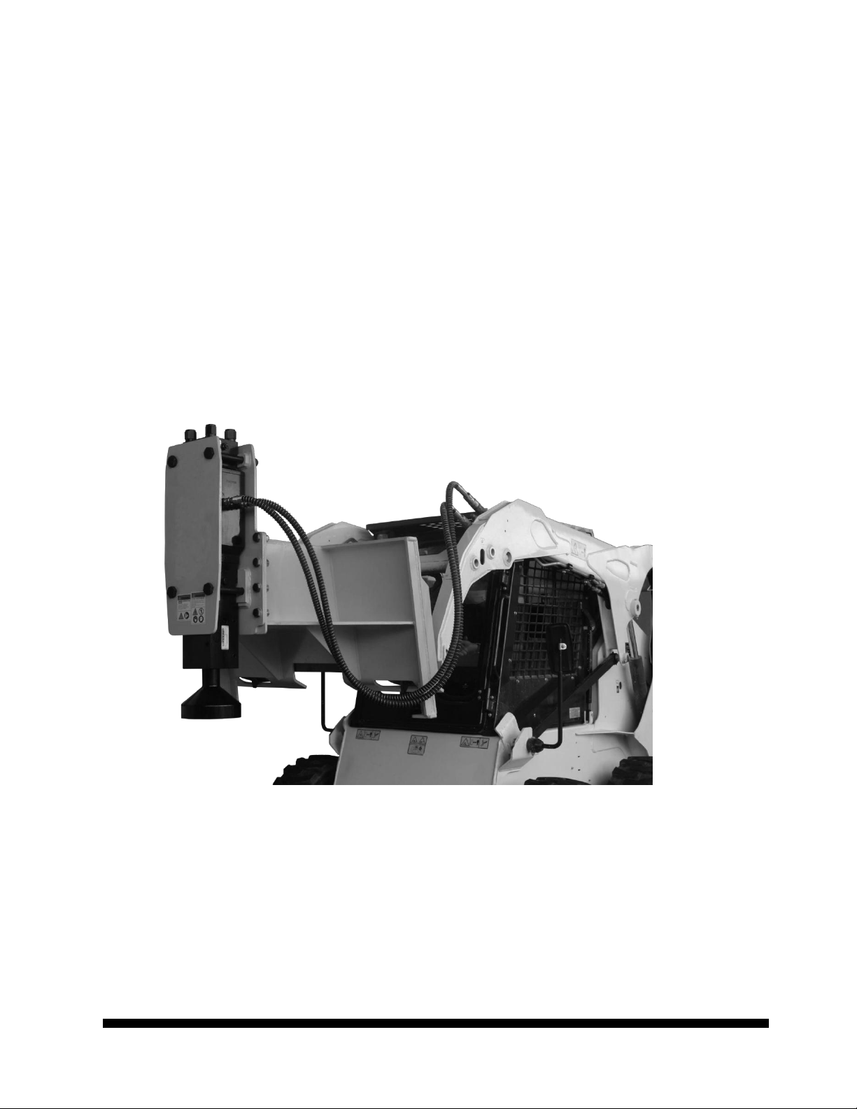
6.1 Operation method
1. Pre-drill a pilot hole if the soil conditions are rocky, frozen, or too difficult to simply drive the post into the
ground.
2. Requires another person to position the pile. This person will set the pile at the desired location and grasp the
pile securely.
3. After the pile is in position, let the Driver onto the top of the pile, ensuring the pile is inside of the bottom portion
of the Driver, and continue lowering the driver until the weight of the Driver is supported by the pile.
After the pile is in position, the person who grasp the pile must leave vehicle as soon as possible.
Don't allow anyone stand under the attachments.
4. Move the vehicle slowly left, right, forward, or backward as needed until the pile is vertical to the ground.
5. The loader arms should be lowered as the pile is driven into the ground.
6. Drive the pile to the desired depth. Raise the Driver and move on to the next pile.
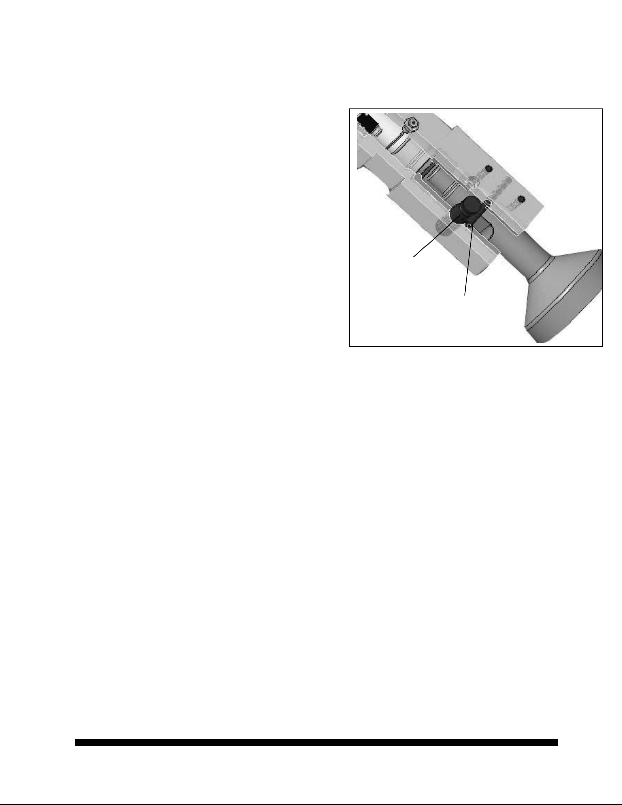
6.2 Operation Precautions
1) Stop operation as soon as hoses vibrate excessively.
Excessive vibration of high and low pressure hoses of the breaker calls for an instant disassembly and
repair.
Contact the nearest service station.
For caution’s sake, check oil leakage at the bank-head.
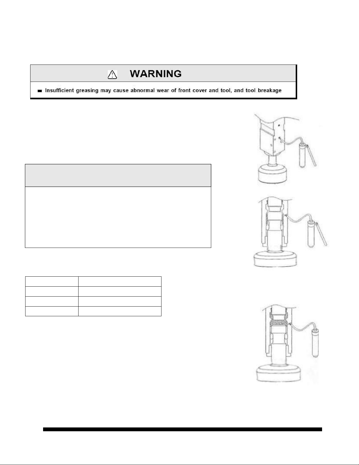
2) Avoid all blank hammering.
Continuous blank hammering will not only damage front head and loosen and break bolts,
but also adversely affect base machine.
Blank hammering occurs when proper position of the Tool is not applied to the Post driver hammer or
the Tool is used as a lever. (Sound changes during blank hammering.)
3) Operate the Post driver hammer at proper engine speed.
Driving the pile at the specified engine speed.
Raising engine speed more than necessary does not strengthen the force but increase oil temperature to the detriment of
the pistons and the valves.
sales@agrotkindustrial.com https://www.agrotkindustrial.com /

4) Do not allow the Post driver hammer to fall to drive the pile.
Dropping the Post driver hammer onto the pile will apply excessive force to the Post driver hammer or the base
machine, causing damage to many parts of the Post driver hammer and the base machine.
Let the driver press the pile to drive it into the ground.
5) Do not lift things with the Post driver hammer.
Lifting materials by hanging wire in the bracket or the Tool not only causes damage to
the Post driver hammer but also is very dangerous when operating.
6) Warm up base machine engine Prior to Operation
Especially in winter, the base machine engine should be warmed up for five to ten minutes
(about oil temperature 30℃~40℃/80℉~105℉) before Post driver hammer operation.
Follow the Instruction Book for the Base Machine for warming-up of the engine.
7) Do not touch the Tool during post driver hammer operation.
During Post driver hammer operation, the Post driver hammer parts can reach high temperatures.
8) When operating the Post driver hammer you must use the ear, eye and breathing
protection.
9) Greasing danger
With the Post driver hammer mounted on the machine, apply down pressure on the Driver Tool.
And fill cavity with the recommended grease through the marked grease nipple.
10) Always wear the eye protection when removing the stop pin.
Remove the stop pin by doing it in and out with a punch and hammer.
sales@agrotkindustrial.com https://www.agrotkindustrial.com /

7. Repair & inspection
7.1 Periodic Maintenance (Every 100 hours)
1) Remove the tool and all grease from the bushing
Do not use a pressure washer, steam or solvents as they damage the seals.
Chuck for chips or cracks inside the housing and on the bushing surfaces.
Cracks and chips could indicate that :
①Lubrication so insufficient
②Grease type is not appropriate
③Blank hammering and side loading is occurring and hammer is being operated improperly.
2) Check wear on Tool Pin
Examine the shoulders and side surface.
If they are worn or deformed, rotate or replace as required.
3) Check wear on chisel holder bushing
Replace tool, bushing or both where the combined wear exceeds 5mm.
Some bushings are grooved to provide even grease distribution.
Replace the bushings when the grooves are worn through.
Excess bushing wear causes tool misalignment to the piston, causing premature Post driver hammer failure.
4) Replace damaged or worn parts
Then wipe all components clean, including the lubrication port.
Hand grease the tool shank and inside the chuck bushings before placing it back into the hammer.
sales@agrotkindustrial.com https://www.agrotkindustrial.com /

7.2 Daily Post driver hammer inspection
Before starting operation, be sure to inspect the Post driver hammer referring to the following table.
Inspection Item
Inspection Point
Remedy
Looseness, missing and
damage bolts and nuts
Through bolts.
Bracket mounting bolts.
Check looseness.
Retighten securely.
Loose of hose fittings,
visible damage to hose
and oil leakage
Hydraulic
driver.
Oil hoses.
popes
for
the
post
Retighten securely.
Replace seriously damaged
parts.
Abnormal oil leakage
Connections of Back head and
cylinder.
Clearance between front head &
Tool.
Consult with local service station
for further inspection.
Abnormal wear
cracks on tool
and
Tool
Deformed, burred and worn out
tool should be repaired.
Excessively worn too needs to
be replaced.
Greasing
Grease at start and every 2 or
3hours using the head grease
pump.
Pumping: 5~10 times (Greasing
position and method shown at
left)
Grease the front head
Level and contamination
of hydraulic oil
Conditions of the hydraulic oil
Contamination of hydraulic oil
varies with operating conditions,
but oil color tells the level of
contamination criteria for judging
contamination is specifically set
by post driver
Missing the rubber plugs
and the snap rings
Rubber Plugs
Snap Rings
A seriously damaged one must
be replaced.
sales@agrotkindustrial.com https://www.agrotkindustrial.com /

7.3 Regular Post driver hammer inspection & Maintenance
Regular inspection is essential for keeping the post driver hammer operating in the best condition.
Consult with the service station for regular inspection and maintenance.
Customers are recommended to contact the local dealer for inspection within six months after delivery.
7.4 Replacement of the Driver Tool
The Tool is deformed by burrs occurring after long-term use. When a Tool tip is worn out,
The Tool is liable to slip. Then, sharpen the Tool tip. Grinding the Tool tip many times to sharpen the edge, but it will
make the heat-treated hardened with a new Tool. If the gap between the Tool and the Tool bush becomes large, the
piston will fail exactly to hit the upper part of the Tool, resulting in damage. When the gap is found to be over 9mm,
replace the Tool bush together with the Tool.
■Change Timing of the Tool Bush (mm)
Model
Wear Limit(mm)
TMG-PD700S
4
sales@agrotkindustrial.com https://www.agrotkindustrial.com /

8.2 Inspection of N2-Gas in the Back-Head
1) Make sure that the cap and the valve of the gas charging kit(⑤) are fully tightened. Screw the gas charging
kit(⑤) into the charging valve of the Back-Head after removing the plug.
2) At this time the handle must be short to prevent the gas from coming out.
3) Push the handle into the charging valve fully, so the gas pressure inside the Back-Head
is indicated on the pressure gauge.
4) If the gas pressure is normal, unscrew the gas charging kit after discharging gas inside
the gas charging kit. Reinsert the plug to the Post driver hammer.
5) If the gas pressure is higher or lower, charge it as described below.
■ Charging of N2-Gas into the Back-Head
1) Connect the charging hose(④) to N2-gas cylinder(①) after screwing the bomb adapter
(④) onto adapter nut(②) and installing than to the N2-gas cylinder.
2) Connect the gas charging kit(⑤) to the charging hose(④) after unscrewing the cap on
the gas charging kit.
3) Install the gas charging kit(⑤) to the charging valve of the Back-Head. At this time the
handle of the gas charging kit must be up position to prevent the gas from comingout.
4) Push the handle of the gas charging kit fully and turn the handle of the N2-gas cylinder
counter clockwise gradually to charge the Back-Head.
5) When the gas pressure exceeds 10% higher then the specified pressure, close the
N2-gas cylinder by turning the handle clockwise.
6) Leave the handle of gas charging kit up. Generated pressure makes, it return back to original position naturally.
7) Remove the charging hose(④) from the N2-gas cylinder(①) and the gas charging kit(⑤), and the screw the
cap onto the gas charging kit.
8) Push the handle of the gas charging kit fully, and the gas pressure inside the Back-Head is indicated on the
pressure gauge. When the pressure is higher, discharge a small amount of gas from the Back-Head repeatedly
opening and closing the valve and then gas pressure falls to the specified pressure.
9) When the gas pressure reaches to the specified pressure, close the valve and release the handle.
10) Open the valve completely and discharge gas inside the gas charging kit. Remove the gas charging kit from the
charging valve of the Back-Head and install the plug to the charging valve.
sales@agrotkindustrial.com https://www.agrotkindustrial.com /

9
TROUBLESHOOTING GUIDE
9.1 Problems in operation
If the Post driver hammer does not work or blow frequency and blow get worse, check following troubleshooting.
And then inspect according to the following order.
Symptom
Cause
Required action
No blow out
1.Excessive back head gas pressure
2.Stop valve (s) closed
3.
Lack of hydraulic oil
4.
Wrong adjustment of pressure
reducing valve
5.
Faulty hydraulic hose connection
6.Oil back head infection
1.Re-adjust nitrogen gas pressure
2.Open Stop Valve
3.
Fill hydraulic oil
4.
Re-adjustment valve
5.Tighten or replace
6.Replace back head O-Ring, Or
cylinder bush stop seal
Low impact power
1.Line leakage or blockage
2.Clogged tank return line filter
3.Lack of hydraulic oil
4.
Hydraulic oil contamination, or heat
deterioration
5.
Poor main pump performance
6.Back head nitrogen gas low
7.Low flow rate by mis-adjustment
of flow control pressure reduction valve
8.Tool out of range for blowing position
1.
check lines
2.
Wash fitter, or replace
3.
Fill hydraulic oil
4.
Replace hydraulic oil, rinse tand
and release oil inside lines
5.Contact authorized service shop
6.Refill nitrogen gas
7.Re-adjust reduction valve
8.Rush down tool by excavator
Irregular impact
1.
Low accumulator gas pressure, of bad
accumulator
2.
Bad piston or valve sliding surface
3.Piston moves down/up to blank blow
hammer chamber
1.
Refill nitrogen gas
2.
Call an authorized service man.
3.Rush down tool by excavator
operation
Bad tool movement
1.
Tool diameter incorrect
2.
Tool and pin jammed from tool retainer
3.Jammed lower bush and tool
4.Deformed tool and piston contact area
1.
Replace tool with genuine
replacement parts
2.
Smoothen rough surface of tool
3.Smoothen rough surface of lower
bush interior
4.Replace tool
Oil leakage between front head
and tool
1.Cylinder seal worn
1.Replace seal
Gas leakage
1.O-ring damage in related parts
1.Replace relevant o-ring
sales@agrotkindustrial.com https://www.agrotkindustrial.com /

10.
CUSTOMERS’ REPORT
10.1 Delivery and Installation Card
This is report is for checking that Post driver hammer is correctly
delivered and equipped on machine Distributor should correctly
draw up this. This is report must be drawn up in typewritten
and Informed within 7 days after the date When delivered Post
driver hammer to customer.
■ Machine
●Maker / Model : Manufacturer and model name of the carrier
●Operating Weight
●Operating Hours : Actual operating hours at time or Date
delivered out Post driver hammer
●Oil Filter – If there is mark “Y” , if not mark “N”
If there is not it or it’s condition is bad, Post driver hammer should be troubled easily.
Therefore please recommend customer to install it in change new one.
●Others : Performance or Condition of Engine and Hydraulic pump.
■ Post driver hammer
●Model & Serial No : Model name and Serial No. of the Post driver hammer
●Operating Pressure : Actual operating pressure
●Relief set Pressure : Actual relief valve setting pressure for Post driver hammer
●Operating Oil Flow : Actual required operating flow
●Gas Pressure : Actual pressure in accumulator or gas chamber
sales@agrotkindustrial.com https://www.agrotkindustrial.com /
Table of contents
Popular Industrial Equipment manuals by other brands

TapFlo
TapFlo DT Series Instructions for installation, operation and maintenance

MITS
MITS FP-21T 60 Maintenance Procedure

Gerber
Gerber SABRE 408 Replacement procedure

Hubbell
Hubbell Walltrak PW2FEBC installation instructions

Hainbuch
Hainbuch TOPlus mini operating instructions

QSA Global
QSA Global OPENVISION DX OVDX-NDT-70 Hardware manual