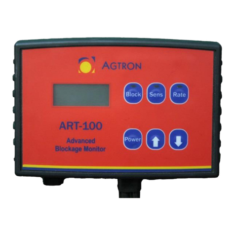
AGTRON CAN ART User manual

CAN ART
Rate and Blockage Monitoring System
Operator’s Manual

MND200704.01 P a g e | 2Software Revision 3.05

MND200704.01 P a g e | 3Software Revision 3.05
1. Quick Start Setup
Important! Must be seeding in order to perform a complete calibration
Work switch
Pressing the
Work Switch
enables all alarms.
1. Grey background indicates Work Switch OFF.
2. Green background indicates Work Switch ON.
3. When the Work Switch is off, all alarms will silence, and area
totals will not accumulate.
Installed Seed Sensors
The system displays the number of
Installed Seed Sensors
on the Main
ART screen.
1. Ensure the correct number of sensors is shown to the right of
the installed sensors icon.
2. If the number is incorrect, see Troubleshooting Table at back of
manual.
Blockage Setup
The goal is to have the Sensitivity value as high as possible without
giving constant alarms. If a seed sensor measures fewer seeds per
second than the Blockage Sensitivity value indicated, a blockage alarm
occurs.
Figure 1-1. Quick Start Setup from Main ART Screen

MND200704.01 P a g e | 4Software Revision 3.05
Set Sensitivity
Important! Must Be Seeding to Set Sensitivity
From the Main ART screen
1. Press the red number to the right of the Sensitivity icon
2. Set the value to 15
3. Increase the sensitivity value by 10
4. Watch for blockage alarm
5. If blockage alarm does not occur repeat steps 3 & 4
6. If blockage alarm does occur, decrease sensitivity value by 3 to 5
Set Sensitivity to zero to turn loop power off
Rate Setup
Rate setup indicates how much product is being put into the ground. A
speed value is required in order to use the Seed Rate Wizard.
Set Speed
1. Press the Calibration Softkey
2. Select the red number to the right of the
Test Speed
icon
(The value should be the speed normally travelled in field.)
3. On the Main ART screen press the speed type button to select
Test Speed
type.
Perform Seed Rate Wizard
Important! Must Be Seeding to Perform Seed Rate Wizard
On the Main ART screen.
1. Press the red number to the right of the
Target Rate
icon
2. Enter the desired rate
3. Press the
Seed Rate Wizard
button.
Speed Type
Select
Tip:
High and Low Seed Rate alarms will
automatically be set when the Seed
Rate Wizard button is pressed.

MND200704.01 P a g e | 5Software Revision 3.05
Follow safety Instructions
Be sure to follow all safety instructions in your air seeder operator’s manual.
Read and Understand This Manual Before Operating This Machine.
Learn how to operate and service the machine correctly. Failure to do so could result in personal injury or equipment damage.
Agtron Enterprises Inc. will not accept any responsibility for any damage or malfunctions resulting from failure to comply with
the operator’s manual.
If you do not understand the information in this manual, or if you have any questions, contact Agtron Enterprises Inc.
Customer Service.
This manual should be considered a permanent part of your machine and should remain with the machine when you sell it.
Agtron Enterprises Inc. reserves the right to alter illustrations and technical data contained in this manual.
The contents of this manual are the intellectual property Agtron Enterprises Inc. All use and/or reproduction not specifically
authorized by Agtron Enterprises Inc. is prohibited.
All information, illustrations and specifications in this manual are based on the latest information available at the time of
publication. Agtron Enterprises Inc. reserves the right to make changes at any time without notice.
ATTENTION! Low battery or alternator voltage can cause system errors.

MND200704.01 P a g e | 6Software Revision 3.05
2. Table of Contents
1. Quick Start Setup........................................................................3
Work switch ...........................................................................................3
Installed Seed Sensors............................................................................3
Blockage Setup.......................................................................................3
Set Sensitivity.........................................................................................4
Rate Setup ..............................................................................................4
Set Speed................................................................................................4
Perform Seed Rate Wizard.....................................................................4
2. Table of Contents ........................................................................6
3. About the CAN ART Rate and Blockage System.....................8
4. Using Virtual Terminals with Your ISO Rate and Blockage
System...........................................................................................9
5. System Installation....................................................................10
CANBUS Harness................................................................................10
CAN Terminating Bias Circuit.............................................................10
Cable Ties and Main Extension Cable Installation...............................10
Main Extension Cables.........................................................................11
Seed Sensor and Sensor Loop Cable Installation .................................11
Y-Cable Installation .............................................................................12
Figure 5-10 Installation Diagram 1 .....................................................13
Figure 5-11. Installation Diagram 2 (Less than 60 Sensors) ................14
Figure 5-12. Installation Diagram 3 (More than 60 Seed Sensors) .....15
Optional Sensor Installation .................................................................16
Figure 5-13 Installation Diagram (Sensor Breakout Cable) ................19
Figure 5-14. Installation Diagram (ART Loop Terminator).................20
6. System Setup and Calibration..................................................21
Softkeys................................................................................................21
Main ART Screen.................................................................................22
Sensitivity.............................................................................................23
Seed Rate Wizard.................................................................................23
High and Low Rate Alarms..................................................................24
Blocked Seed Sensors ..........................................................................24
Installed Seed Sensors..........................................................................24
Clean Seed Sensor................................................................................25
Figure 6-2. Communications Errors Screen ........................................25
Figure 6-3. Calibration Screen ............................................................26
Unlock Softkey.....................................................................................26
Default Calibration softkey ..................................................................27
Master and External Toolbar Work Switches.......................................27
Implement Width..................................................................................29
Row Count ...........................................................................................29
Seed Delay ...........................................................................................29
Minimum Speed...................................................................................29
Setting Up Speed Sensor......................................................................30
Area 1 and Area 2.................................................................................31
Setting Up Fan Sensors ........................................................................31
Setting Up Shaft Sensors......................................................................32
Setting Up Bin Sensors.........................................................................33
Sensor Assignments .............................................................................34
Sensor Logic.........................................................................................34
Units of Measurement ..........................................................................35
Current Overload..................................................................................35
SPI Communication .............................................................................35
ECU Voltage ........................................................................................35
Battery Voltage ....................................................................................35

MND200704.01 P a g e | 7Software Revision 3.05
Current..................................................................................................35
Figure 6-5. Seed Sensor Shutoff Screen..............................................36
Loop 1 and 2 Seed Sensor Pattern........................................................37
7. Diagnostics and Troubleshooting.............................................38
Figure 7-1. System Alarms................... Error! Bookmark not defined.
Alarm Screens ......................................................................................38
Diagnostics and Troubleshooting Table...............................................44
8. Appendix....................................................................................47
Appendix A: Parts List.........................................................................47
Appendix B: Optional Sensors.............................................................48
Appendix C: Seed Sensor Sensitivity Values.......................................50
Appendix D: Conversion Factors.........................................................51
Appendix E: Seed Densities.................................................................52
Appendix F: Sensor Breakout Connector Pin-out ................................53
Appendix G: DSUB Connector Pin-out ...............................................53
Appendix H: DTM Connector Pin-out.................................................53
9. Warranty....................................................................................54
Warranty Guidelines ............................................................................54

MND200704.01 P a g e | 8Software Revision 3.05
3. About the CAN ART Rate and Blockage System
ISO Compliant (CAN- 2.0b ISO 11783)
The CAN ART is a Rate and Blockage ECU that is ISO compliant with
functionality UT 2.0 which is capable of operating on any Virtual
Terminal (VT) on a CAN 2.0b bus. The CAN protocol is based on the
ISO 11783 standard. It operates with basic functionality which includes
blockage detection of all sensors every second.
The CAN ART uses infrared seed sensors to measure seed rate and
check for blockages. The sensors operate on a similar principle to that of
a motion detector in a security system.
2 Loops –120 Sensors
The ECU can communicate with two individually controlled Sensor
Loops each capable of handling 120 seed sensors. The only required
setup value is a sensitivity value that sets the minimum seeds/second
limit to eliminate blockage alarms.
The ECU is also able to monitor up to six additional sensors (shaft, fan,
bin, work, speed, etc.) connected through an optional Sensor Breakout
Harness on each Loop.

MND200704.01 P a g e | 9Software Revision 3.05
4. Using Virtual Terminals with Your ISO Rate and
Blockage System
Several companies manufacture ISOBUS compatible Virtual Terminals.
Although the locations and types of controls may vary from
manufacturer to manufacturer, all terminals use the same icons to
represent the main functions.
Any ISOBUS compatible virtual terminal (VT) should be able to
communicate with and control your CAN ART. When the VT in your
tractor is connected to the CAN ART it downloads the information
from the ECU and displays it on the VT’s screen. The central part of the
screen displays information pages identically, regardless of the VT you
are using. Typically, icons representing other pages are located around,
or to the side of the central part of the screen. Selecting these soft keys
enables you to navigate to the pages they represent. The location of page
icons may vary depending on the manufacturer of the VT. Also, some
VTs have touch screens, whereas others use pushbuttons located around
the outside of the screen, adjacent to on-screen icons.
ISOBUS compatible VTs can be used to set up, operate and monitor
your ISOBUS Rate and Blockage system, but the exact details of how to
access and change values and settings may vary from manufacturer to
manufacturer. For example, when entering numerical values during
system setup, some VTs may open a keypad-style page. Others may
assign numbers to buttons around the outside of the screen. For this
reason, procedures in this manual simply state “Enter the numerical
value for…” You will have to consult the manufacturer’s operating
manual for your specific VT to determine the details.
Go to www.agtron.com to view the current Virtual Terminals that can
be used with your Rate and Blockage system.
Tip:
For detailed information on how to
operate your Virtual Terminal, refer to its
operation manual.
Figure 4-1.

MND200704.01 P a g e | 10 Software Revision 3.05
Figure 5-3.
5. System Installation
CANBUS Harness
For Installation of CANBUS Harness on non-ISO Tow Between Air
Cart setup or Tow Behind Air Cart setup plug the CANBUS Harness
into the ISO plug on the rear of the tractor. (See Figure 5-1)
1. For Installation of CANBUS Harness on ISO Tow Between Air
Cart setup, you can plug the CANBUS Harnesss into the ISO
plug on the rear of the Air Cart.
2. Select a mounting location to protect the ECU
3. Affix the ECU to the frame of the tank or toolbar.
4. Connect the CANBUS Harness Cable to the DSUB connector
on the ECU with two (2) jackscrews. (See Figure 5-2)
Figure 5-1.
CAN Terminating Bias Circuit
A CAN Terminating Bias Circuit connector must be installed on the
CANBUS Harness Cable if there is no other ECU installed at the end of
the system.
Cable Ties and Main Extension Cable Installation
The colored cable ties included in this kit are to assist in easy installation
and to differentiate between the two loops of sensors.
1. Attach blue ties for all Loop 1 cables.
2. Attach yellow ties for all Loop 2 cables.
Figure 5-2.
Figure 5-4.

MND200704.01 P a g e | 11 Software Revision 3.05
Main Extension Cables
When making Extension Cable connections, make sure you align the
molded arrows. If they are difficult to push together, check the condition
of the pins. For each Loop (1 for Single; 2 for Dual):
1. Connect the cable from the ECU to a 10ft or 20ft Main
Extension Cable.
2. Route the Main Harness Extension Cable to the implement
hitch.
3. Secure the Main Harness Extension Cable to the equipment with
cable ties, allowing enough slack for hitch movement.
Seed Sensor and Sensor Loop Cable Installation
1. Select a mounting location near the distributor.
Locate the Seed Sensors in the hose above the implement chassis
to protect the Seed Sensors and cables from field debris damage.
2. Secure the Seed Sensors in the hose using metal hose clamps on
each side (Agtron Part# 400TRHS16 not included).
3. Select a seed sensor on the far left of the machine to be seed
sensor #1. Leave the female plug of this sensor unplugged, but
connect the male plug to the seed sensor beside it. This will be
sensor #2.
4. Continue connecting seed sensor #2 to seed sensor #3 and so
on, until the manifold is all connected. Attach a Sensor Loop
cable to the male end of the last sensor on the first manifold.
5. Connect the male end of the Sensor Loop Cable to the female
end of the first seed sensor on the second manifold. Continue in
this fashion until you reach the far right side of the implement,
leaving the male end on the last sensor unplugged.
6. Using cable ties attach all cables to the frame of the implement.
Avoid pinch points such as wing & opener lift points.
The Sensor Loop Cables should not be stretched tight when
connected.
Tip:
To help avoid electrical interference problems, create a figure eight shape
with excess cable before securing.
Tip:
If necessary, apply heat to the hose ends
in order to fit the hose over the sensor.
Figure 5-5.
ECU Female Extension Cable Male
Figure 5-6.
Figure 5-7.
Figure 5-8.

MND200704.01 P a g e | 12 Software Revision 3.05
Y-Cable Installation
For the following installation procedures, refer to the Installation
Diagrams. (Figure 5-10, Figure 5-11 & Figure 5-12)
1. Select a mounting location for the Y-Cable in the center of the
implement.
2. Secure the ring terminal of the Y-Cable to the chassis of the
implement to ground the cable.
3. Connect the Y-Cable’s male Sensor Loop Cable to Seed Sensor 1
(normally located on the far left side of the implement) using
Sensor Loop Cables as required.
4. Connect the Y-Cable’s male Sensor Loop Cable to the last Seed
Sensor (normally located on the far right side of the implement)
using Sensor Loop Cables as required.
Y-Cable (More than 60 Sensors)
On systems with more than 60 Seed Sensors, an additional Y-Cable must
be installed in the middle of the loop to improve power distribution.
1. When making Sensor Loop cable connections, make sure you
align the molded arrows. If they are difficult to push together,
check the condition of the pins.
2. To prevent cable damage, route the cables so they follow the
hydraulic hoses whenever possible.
3. Connect the blue male end of the second Y-Cable to the blue
female end of the first Y-Cable.
4. Connect the second Y-Cable’s male and female Sensor Loop
cables into the middle of the seed sensor loop (Using in place of
a Sensor Loop cable)
Figure 5-9

MND200704.01 P a g e | 13 Software Revision 3.05
Figure 5-10 Installation Diagram 1
Item
Part Number
Description
1
AGD2110
AGD2210
Single Loop CAN ART ECU
Dual Loop CAN ART ECU
2
AGD2003
CANBUS Harness
3
AGD3093
CAN Terminating Bias Circuit
5
MND2007
Manual
6
4TYWR14.0
850040001
850040002
Black Cable Ties (14.5”)
Blue Cable Ties (4”)
Yellow Cable Ties (4”)
Figure 5-10 Installation Diagram 1

MND200704.01 P a g e | 14 Software Revision 3.05
Figure 5-11. Installation Diagram 2 (Less than 60 Sensors)
Item
Part Number
Description
1
9ARTM10
9ARTM20
Main Extension Cable 10FT
Main Extension Cable 20FT
2
9ARTY10
ART Y-Cable
3
9ARTX02
9ARTX04
9ARTX10
9ARTX20
ART Sensor Loop Cable 2ft (0.6m)
ART Sensor Loop Cable 4ft (1m)
ART Sensor Loop Cable 10ft (3m)
ART Sensor Loop Cable 20ft (6m)
4
AGSS22
AGSS24
AGSS25
AGSS32
ART Seed Sensor 7/8” (22mm)
ART Seed Sensor 15/16” (24mm)
ART Seed Sensor 1” (25mm)
ART Seed Sensor 1 1/4” (32mm)
5
400TRHS16
Hose clamp size 16
Diagram dimensions are not to
scale
Figure 5-11. Installation Diagram 2 (Less than 60 Sensors)

MND200704.01 P a g e | 16 Software Revision 3.05
Optional Sensor Installation
Sensor Breakout Harness connectors #4, 5, and 6 are for Loop 1; Connectors 7, 8, and 9
are for Loop 2 (See Figure 5-13 and Figure 5-14). Refer to Appendix B for more
information
Automatic Work Switch
Requires Toolbar Sensor Breakout Harness and Shaft/Work Switch
Sensor.
1. Install the Work Switch Sensor and magnet on the toolbar in a
place where the magnet and sensor are within ½” of each other
in the working position and far from each other when not
working (when the drill is up).
2. Connect the Work Switch Sensor to one of the connectors on
the Toolbar Sensor Breakout Harness. Make note of the channel
number you have selected.
3. Connect the Toolbar Sensor Breakout Harness in-line with the
Y-Cable. (See Figure 5-13 & Figure 5-14)
4. Turn to the Calibration portion of this manual for information
on how to set up optional sensors in the system.
Shaft Sensor
Requires Toolbar Sensor Breakout Harness and Shaft Sensor.
1. Attach the supplied magnet to a Shaft (rotation under 1000rpm).
2. Select a mounting location for the sensor within ½” (13mm) of
the magnet.
3. Connect the Shaft Sensor to one of the connectors on the
Toolbar Sensor Breakout Harness. Make note of the channel
number you have selected.
4. Connect the Toolbar Sensor Breakout Harness in-line with the
Y-Cable. (See Figure 5-13 & Figure 5-14)
5. Turn to the Calibration portion of this manual for information
on how to set up optional sensors in the system.

MND200704.01 P a g e | 17 Software Revision 3.05
Fan Sensor
Requires Toolbar Sensor Breakout Harness and Fan Sensor.
1. Mount the sensor within 1/16” (1mm) of a ferrous metal target
such as a bolt head. (Over 500rpm).
2. Connect the Fan Sensor to one of the connectors on the Toolbar
Sensor Breakout Harness. Make note of the channel number you
have selected.
3. Connect the Toolbar Sensor Breakout Harness in-line with the
Y-Cable. (See Figure 5-13 & Figure 5-14)
4. Turn to the Calibration portion of this manual for information
on how to set up optional sensors in the system.
Bin Sensor
Requires Toolbar Sensor Breakout Harness and Bin Sensor.
1. Select a mounting location in the tank at the desired empty
product level. The Bin Sensor alarms when product does not
cover it.
2. In the selected mounting location, drill a 1/4” (6mm) hole. This
is the hole for the bin sensor cable.
3. Drill a 1/8” hole, 1 5/8” on either side of the first hole. These
are the holes for mounting the bin sensor.
4. Using needle nose pliers, take apart the Deutsch connector on
the bin sensor cable.
5. Instructions on how to take apart the connector are included in
the bin sensor kit.
6. Route the cable through the ¼” hole.
7. Put the Deutsch cable back together. (Pin 1:Red, Pin 2:Green,
Pin 3:Black)
8. Secure the Bin Sensor to the mounting location with the #8
Philips Screws provided. Depending on the thickness of the tank,
either ½” or 1” can be used.
9. Connect the Bin Sensor to one of the connectors on the Toolbar
Sensor Breakout Harness. Make note of the channel number you
have selected.
10. Connect the Toolbar Sensor Breakout Harness in-line with the
Y-Cable. (See Figure 5-13 & Figure 5-14)
11. Turn to the Calibration portion of this manual for information
on how to set up optional sensors in the system.

MND200704.01 P a g e | 18 Software Revision 3.05
Speed Sensor
Requires Toolbar Sensor Breakout Harness and Speed Sensor.
1. Attach the supplied magnet to a wheel or shaft that turns when
the seeder is in motion.
2. Select a mounting location for the sensor within ½” (13mm) of
the magnet.
3. Connect the Speed Sensor to one of the connectors on the
Toolbar Sensor Breakout Harness. Make note of the channel
number you have selected.
4. Connect the Toolbar Sensor Breakout Harness in-line with the
Y-Cable. (See Figure 5-13 & Figure 5-14)
5. Turn to the Calibration portion of this manual for information
on how to set up optional sensors in the system.

MND200704.01 P a g e | 19 Software Revision 3.05
Figure 5-13 Installation Diagram (Sensor Breakout Cable)
Item
Part Number
Description
1
9ARTM10
9ARTM20
ART Main Extension Cable 10FT (3M)
ART Main Extension Cable 20FT (6M)
2
9ARTY10
ART Y-Cable
3
9ART036
Toolbar Sensor Breakout Harness
Optional Sensors
Item
Part Number
Description
4
9AGPS01
9AGPS02
GPS Speed Sensor (5Hz update speed)
GPS Speed Sensor (1Hz update speed)
AGBN007
AGBN008
Bin Sensor 20FT (6M)
Bin Sensor 6FT (1.8M)
9ART090
3P Deutsch to AMP CPC Radar Adapter
9ART091
3P Deutsch to AMP CPC Radar Y-Cable
AGCS001
Capacitive Proximity Sensor 6FT (2M)
AGIND01
Inductive Proximity Sensor 20FT (6M)
AGSH001
Low RPM Reed Switch Sensor 20FT (6M)
9KRT069
3P Deutsch to Relay Kit
9ART089
3P Deutsch With Bare Wire Ends
Figure 5-13 Installation Diagram (Sensor Breakout Cable)

MND200704.01 P a g e | 20 Software Revision 3.05
Figure 5-14. Installation Diagram (ART Loop Terminator)
The Terminator will go at the end of the second loop Sensor Breakout
cable if no Seed Sensors are installed, this is to get the monitor to
provide constant power to the loop when other sensors are installed (i.e.:
Fan, Shaft and Bin). The Monitor will recognize this as a loop with zero
seed sensors. The terminator has a red LED to indicate power is ON.
Item
Part Number
Description
1
9ARTM10
9ARTM20
10 FT Main Extension Cable
20 FT Main Extension Cable
2
9ART036
Toolbar Sensor Breakout Harness
3
AGRT071
ART Loop Terminator
Optional Sensors
Item
Part Number
Description
4
9AGPS01
9AGPS02
GPS Speed Sensor (5Hz update speed)
GPS Speed Sensor (1Hz update speed)
AGBN007
AGBN008
Bin Sensor 20FT (6M)
Bin Sensor 6FT (1.8M)
9ART090
3P Deutsch to AMP CPC Radar Adapter
9ART091
3P Deutsch to AMP CPC Radar Y-Cable
AGCS001
Capacitive Proximity Sensor 6FT (2M)
AGIND01
Inductive Proximity Sensor 20FT (6M)
AGSH001
Low RPM Reed Switch Sensor 20FT (6M)
9KRT069
3P Deutsch to Relay Kit
9ART089
3P Deutsch with Bare Wire Ends
Tip:
A Y-Cable with the Seed
Sensor connections mated
together can be
substituted for the
terminator
Figure 5-14. Installation Diagram (ART Loop Terminator)
Table of contents
Other AGTRON Measuring Instrument manuals