Thank you for choosing our
Barriquan
. Please read this Instruction Manual carefully before using this product
and keep this at hand whenever the operator can read. If you have any questions on about this product or in this
manual, please feel free to contact us at your nearest office.
1.For Your Safety
For operating this product safely, please read
cautions in this Instruction Manual thoroughly and
understand them enough before using「
Barriquan
」.
There are “safety alert marks”in this manual and it’s
represented as 「Cautions」. This symbol is used to
call your attention to items or operation that should be
cautious.
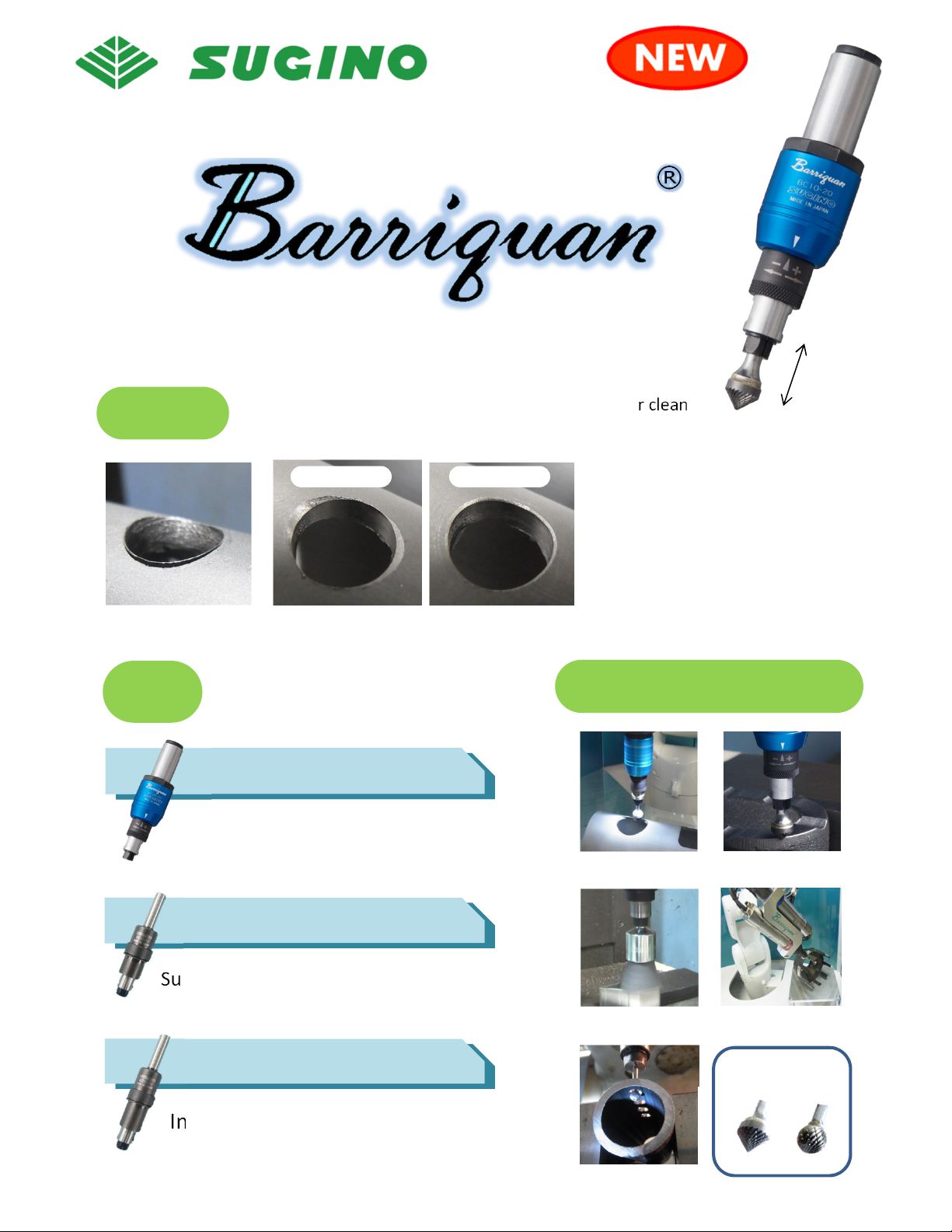
2.Specification
Barriquan
is a tool holder for deburring which has a
floating structure extendable within the range 10 mm.
By this floating structure, the cutter edge can move
automatically along the workpiece shape and deburr.
Besides, this has another structure which is able to
adjust Spring Pre-load depending on the burr.
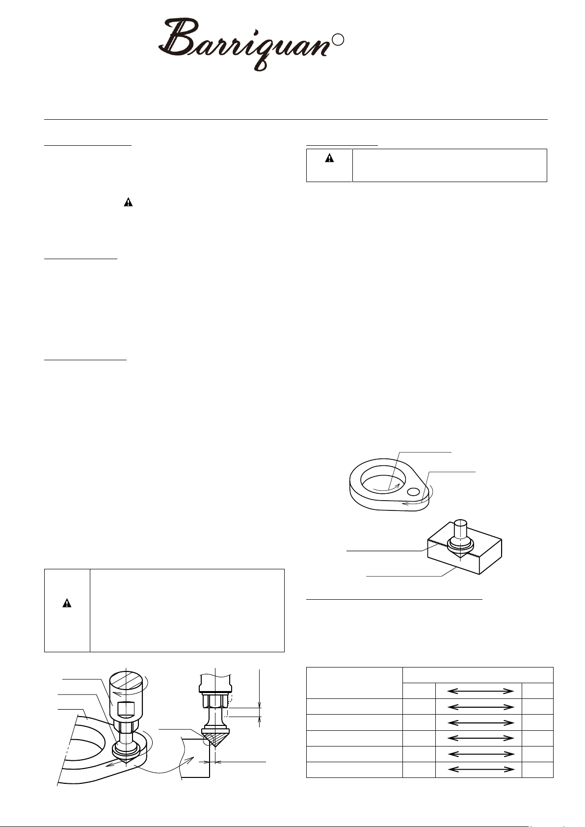
3.Method of Use
Attach Cutter to φ6 Collet. (Spanner size [nominal]:
10 mm, 13mm) Fastening torque of Collet is 12N・m.
Offset this tool about half of Cutter radius as Cutter
taper center can contact the burred part of workpiece.
And then, use this tool compressing Cutter about 1~
5mm (Figure1). Processing Parameter in Figure 1 will
be changed depending on the chosen Cutter. Please
set the suitable parameter for the attached Cutter.
The maximum number of rotation is 5000min-1. Please
do not over this maximum when using this tool.
Please test the workpiece as a trial at first and then
process them continually. At the trial test, start the
process low parameter (Pre-load and compression
amount) and then try gradually higher parameter to
achieve the requested finish. Please refer to “3-2.
Adjustment for Processing Parameter”.
At the trial test, start the process low
parameter (Pre-load and compression
amount) and then try gradually higher
parameter to achieve the requested
finish. If the parameter is excessive, the
floating structure may not work and it
leads to the tool broken soon.
3-1.Cautions
Please use this holder normal rotation. If
using this reverse rotation, Collet may be
loosened and it may cause the tool broken.
For deburring, please use it by Down-Cut. (Figure 2)
This tool holder is for the front side surface of workpiece.
This cannot be used for the backside surface to deburr.
(Figure 3)
When measuring Cutter projection, etc., please check if
Collet is projected max. length from Stem If pre-load is
weak, Collet may be retracted. In that case, please
increase pre-load.
This tool does not have a floating structure for radial
direction. Do not choose Cutter and Cutting method
which give excessive load to the directions except axial
direction.
When using cutting fluid, do not pour it to
Barriquan
directly. If the fluid comes inside the tool, it may lead the
malfunction.
Rotate the tool and deburr along workpiece shape. (Do
not use this without tool rotation.) If using without tool
rotation, floating function does not work and it may lead
to the tool broken.
When attaching this product to tool holder, etc., please
do not tighten this too much. In case of excessive
fastening, this tool may not work properly.
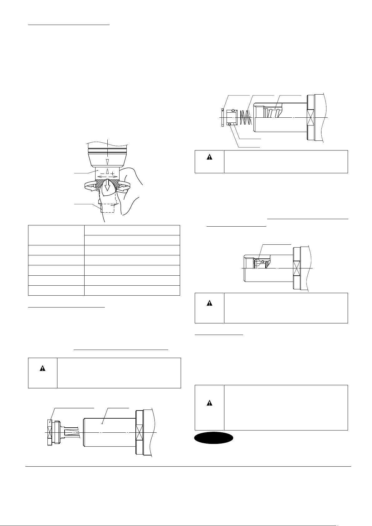
3-2.Adjustment for Cutting Amount
For adjustment of cutting amount, please refer to
the below chart and adjust the processing parameter.
When making cutting amount bigger, please increase
it gradually. For Spring pre-load, please refer to “4.
Adjustment for Spring Pre-load”.
Offset length
1/2 Cutter Radius
Counter-clockwise for inner edge
Available for front side burr
Non-available for backside burr
(example of 90°Cutter use)