9
Specications and Need-to-Know Information
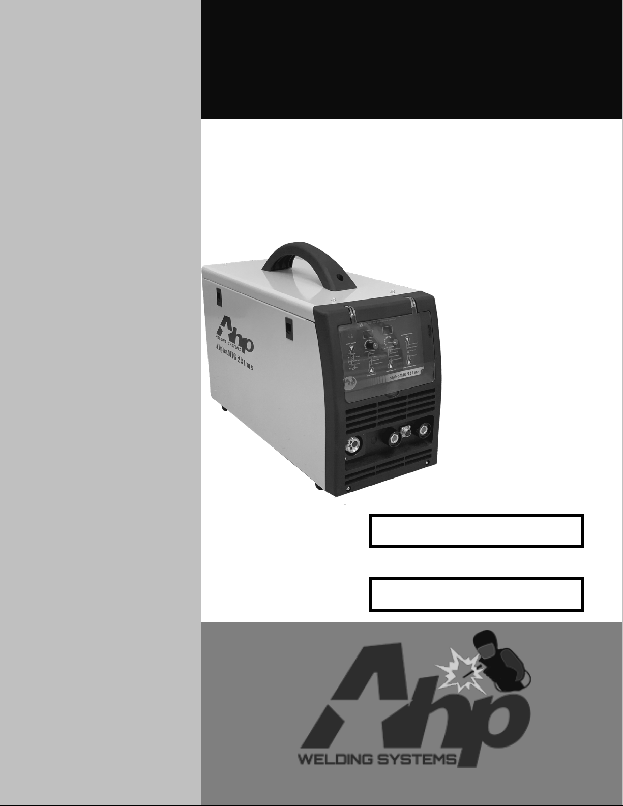
alphaMIG 231ms
About the AlphaMIG 231ms
The AlphaMIG 231ms is a class-leading MIG/Stick welder design from
AHP. It is capable of MIG, Gasless Flux-cored, and DC Stick welding.
This combination of functions allows the user to cover a broad spec-
trum of welding needs. This unit’s design, combined with its out-
standing duty cycle, ends itself well to small fabrication and body
shops as well as production facilities.
The MIG process gives the user the ability to join nearly any metal.
Even aluminum can be joined with ease (1/8-5/16”). This unit can be
used with the optional spool gun which allows the user to weld Alumi-
num or the standard 10 ft. MIG gun equipped with the optional poly-
mer liner and optional U-groove drive rolls (best for .035 and .045”
wire).
The stick welding process provides excellent “on the job site” capabil-
ity for manufacturing and repair. This unit utilizes the latest in digi-
tally controlled IGBT inverter welding technology, while providing the
user with an easy-to-use interface. This unit will run most electrodes
up to 1/8” smoothly. When using electrodes with a cellulose flux base,
such as E6010 and E6011, the arc gap must be held tight.
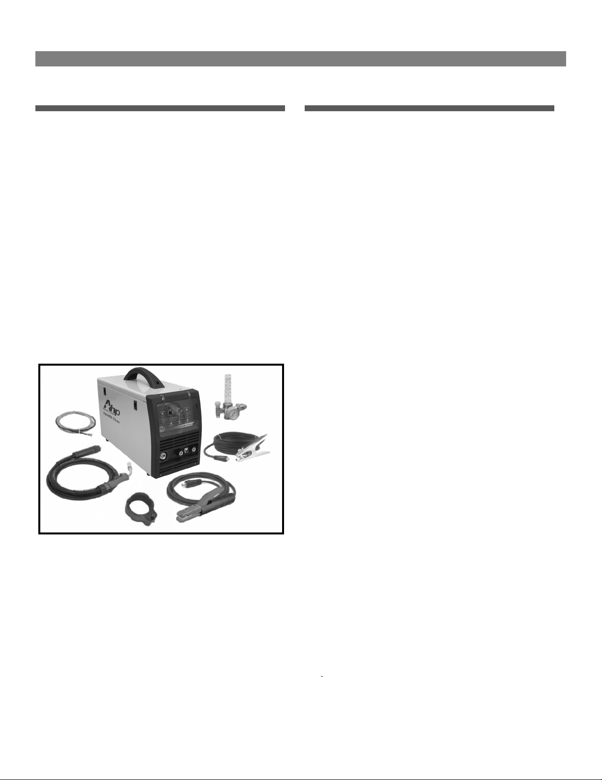
The unit comes standard with the following items and features:
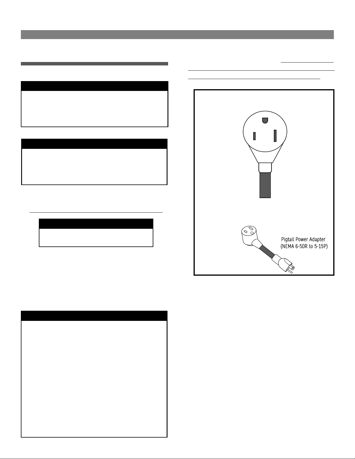
• Dual Voltage 120/240V operation capability
• 230A MIG, 180A DC Stick Output
• Spool Gun capable (Spool Gun is sold separately)
• Euro-Type Quick Connector
• 24 series MIG gun 3m (10 ft)
• 250A Stick Electrode Holder 2m (6.5ft)
• 250A work clamp 2m (6.5 ft)
• Billet Brass Floating Ball type MIG Ar/CO2 Gas regulator
• MIG Tips
• 240V to 120V Stepdown pigtail adapter
Ahp Warranty Statement
WARRANTY ONLY APPLIES TO UNITS WITH PROOF OF PURCHASE
FROM AN AUTHORIZED DEALER. NO EXCEPTIONS. PLEASE FEEL FREE
TO REQUEST A LIST OF AUTHORIZED DEALERS.
The AHP Golden Circle Warranty:
All new AHP welders, shall be warrantied to the original owner for a
period to extend for 3 years from date of purchase against breakage,
malfunction, or other unit failure resulting from manufacturing de-
fect. The faulty unit will either be repaired or an exchange will be
made for a new or factory reconditioned unit at AHP Welds discretion.
The customer must contact the technical support team to review unit
failure so that the warranty claim can be established. Items such as
electrodes, contact tips, nozzles, cups, shields, liners etc, considered
to be consumable items, are NOT covered under warranty. Torches,
foot pedals and spool guns are warrantied for a period of 6 months.
Additionally, certain items such as torches, foot pedals and easily
serviced parts may be individually exchanged without returning the
entire unit assembly should a failure with these items occur, at AHP
Welds discretion. AHP Welds will not be responsible for time/contract
loss from unit failure, damages occurring from improper or unskilled
operation, damages resulting from improper maintenance, improper
wiring, poor quality power sources, abuse or neglect. Nor will AHP
assume responsibility for the customer's failure to heed/read safety
instructions, to read and understand operator's manual, obey occupa-
tional laws or to ensure the unit's safe operation complies with state
or local laws, personal injury arising from the inherent risks involved
with welding, including burns, electric shock or death. Warranty ex-
tends only to the machine, its accessories and parts contained inside
as stated above. No other warranty is expressed or implied.
In the event of unit failure or malfunction, the customer must contact
AHP to obtain a location of a designated return/repair facility. The
replacement/repaired unit will then be returned to the customer.
Additionally for USA customers, AHP offers shipping coverage in the
lower 48 states for a limited time. Please call with receipt to verify
shipping coverage status. After the shipping coverage time ends, the
customer shall be responsible for all shipping and handling costs
both ways of non-functioning units for repair or replacement. Cus-
tomers located outside of the USA lower 48 states will have to pay
shipping and handling charges both ways from the purchase date. It
is the customer's responsibility to adequately insure the unit, as AHP
is not responsible for lost or damaged returns. Labor coverage only
applies if the unit is serviced at our facility or one of our authorized
dealers. We will not reimburse the labor if the customer decides to
have a third-party or unauthorized repair technicians work on the
unit.
View full warranty, terms of sale and shipping details here:
https://ahpwelds.com/