manuals.online logo
Brands
  1. Home
  2. •
  3. Brands
  4. •
  5. AHP
  6. •
  7. Welding System
  8. •
  9. AHP alphaCUT 825i User manual

AHP alphaCUT 825i User manual

OPERATOR’S MANUAL
SAFETY AND USE INSTRUCTIONS
alphaCUT 825i
Serial Number
Purchase Date (Attach Receipt to Cover For Proof of Purchase)
Need Information?
Contact:
[email protected]
925-391-3599
Technical Issues?
Contact:
[email protected]
925-391-3599 (Ext. 102)
Issue Date: 04/12/2023
Publication: AHP825i-103
© Ahp Welding Systems 380 Swift Ave. #11 South San Francisco, CA 94080
2
CONTENTS
Shipping Issues? 3
CA Proposition 65 Warning 4
Safety First Information 5
Safety Warning, Dangers, Cautions and Instructions 6
About the Alpha TIG 203Xi 9
Warranty Statement 9
Specifications 10
Generator Operation Information 11
Duty Cycle Performance 11
Routine Required Maintenance 11
HF Point Gap Maintenance 12
TIG Shielding Gas Information 13
TIG Polarity and Tungsten Type 14
Tungsten Preparation 15
Stick Polarity and Electrode Types 15
Front Panel Features 17
Rear Panel Features 17
Control Panel Features 19
LCD Screen Features 21
Using AC Controls in TIG Welding 23
Using 2T/4T/Pedal Functions 24
Pulse Use and Operation 25
Starting the TIG Arc 26
Welding in Stick Mode 27
Useful TIG Settings 28
26 Series Air-Cooled TIG Torch Information 29
Pinout Connector Information 29
Trouble Shooting 30
3
IMPORTANT! This unit has been thoroughly tested and inspected for function at the factory. However, you should be prepared to inspect
and test this unit completely within 72 hours after receipt. Please do not delay in doing this. Ahp needs to know if there is any damage
caused in shipping as soon as possible. Damage caused by shipping and discovered after 30 days due to lack of inspection will not be
covered under the free 30 day shipping policy.
Please contact us immediately should you have any questions or concerns about the plasma cutter after delivery. We’ll be glad to help.
SHIPPING ISSUES?
4
WARNING!
California Proposition 65 Warning:
This product, when used for welding or cutting, produces
fumes or gases which contain chemicals known to the State
of California to cause birth defects and, in some cases, can-
cer. (California Health & Safety Code § 25249.5 et seq.)
Warning: Cancer and/or Reproductive Harm
www.P65warnings.ca.gov
NOTICE:
Due to our constant effort to improve our products, specica-
tions are subject to change without notice or revision to this
manual. In addition, minor changes in product cosmetics,
accessory type and quantity may change without notice.
These do not constitute a major change in function or opera-
tion.
Ahp Welding Systems makes no warranty for merchantability
or tness for a particular purpose or application. Any claims
of such are expressly denied by Ahp Welding Systems. Fur-
thermore, Ahp Welding Systems does not accept liability for
injury or damages, consequential or incidental, resulting
from the use of this product or resulting from the content
found in this document or accept claims by a third party of
such liability.
5
SAFETY FIRST!
Ahp Welding Systems takes safety seriously. You should as well. Please read
this entire manual before using. Keep a copy of this manual available for all
employees or potential users of this machine to read and thoroughly review
before use.
No matter how detailed may be nothing can substitute for careful planning
and common sense required to operate and safe work environment.
Welding is an inherently dangerous activity. Failure to follow safety protocols
while welding may result in severe burns, blindness, severe shock, or death
from electrocution.
BE AWARE OF YOUR WORK AREA AND THE WHO OR WHAT IS IN IT!
AS THE USER OF THIS PRODUCT YOU ARE RESPONSIBLE FOR YOUR OWN
PERSONAL SAFETY AND FOR THE SAFETY AND SECURITY OF THE PEOPLE
AND ITEMS AROUND YOU!
If you feel you do not have the resources to provide a safe work environment,
or do not have the skills or (for whatever reason) the capability to safely oper-
ate this unit, do not use this unit until you seek professional instruction in safe
operation and care of this unit.
NOTICE:
Welding and cutting operations may generate undesira-
ble High Frequency (HF) and EMF energy. This can in-
terfere with surrounding electronic equipment such as
computers, routers, CNC equipment, televisions, radios,
uorescent lighting etc. If disturbance in surrounding
electrical and electronic equipment is noted, consult a
licensed electrician to help properly ground surrounding
equipment to limit the interference. This machine may
cause GCFI and ground fault outlets to malfunction.
This unit is designed to be operated on a dedicated,
properly grounded circuit.
6
Safety Warnings, Dangers, Cautions and Instructions
NOTICE: This unit manual is intended for users with basic knowledge and skillset in welding and
cutting operations. It is your responsibility to make certain that the use of this cutter is restricted to
persons who have read, understand and follow the warnings and instructions in this manual. If you
or the operator needs further instruction, contact AHP welding support or seek qualified professional
advice and training.
WARNING! High Frequency (HF) energy can interfere with the operation of pacemakers and can dam-
age pacemakers. Consult with your physician and pacemaker manufacturer before entering an area
where welding and cutting equipment is in operation and before using this cutter. Some pacemak-
ers have limited shielding. Alert any users or customers of this potential problem.
WARNING! Use approved safety glasses with wrap around shields and sides while cutting and work-
ing in the weld area or serious eye damage or loss of vision may result. Use a grinding shield in
addition to the safety glasses during chipping and grinding operations. Have other workers in the
area use at least a shade 5 for indirect viewing of cutting work.
WARNING! When always use an approved welding helmet or shielding device equipped with at least
an equivalent of a shade 8 or greater when directly viewing the cutting arc. Increase the shade
number rating as amperage increases to 80 amps. Inspect helmet or shielding device for cracks in
lenses and in the helmet. Keep lens covers in good condition and replace as necessary.
WARNING! Welding/cutting operations carry inherent risks which include but not limited to possible
cuts burns, electrical shocks, lung damage, eye damage and even death. Take all appropriate
measures to use proper Personal Protective Equipment (PPE). Always use leather welding gloves,
closed toe (preferably reinforced or steel toe leather shoes, and long-sleeved flame resistant clothing
(i.e. denim). Do not wear Poly/Nylon blend materials.
DANGER! Welding/cutting poses shock and electrocution risks. Keep this welding equipment dry. Do
not weld in the rain or where moisture accumulates. Use dry, rubber soled shoes, gloves and cloth-
ing when welding. Do not rest or contact work clamp (ground) when welding. Keep all parts of the
body insulated from the part being welded when possible. Do not touch terminals or connections
while the unit is on. Consider all parts to be “live” at all times even if no live work is being per-
formed. Do not use frayed welding cables.
CAUTION! Fires are possible but also preventable while welding. Always remove flammable rags,
papers, and other materials from the weld area. Keep rags stored in an approved flame proof canis-
ter. Keep a fully charged fire extinguisher at hand. Remove any fuels, oils, paint, pressurized spray
cans, and chemicals from the weld area. Make sure any smoke/fire detectors are function properly.
Do not weld on tanks, drums or barrels, especially if pressurized or sealed. Do not weld on any con-
tainer that previously held fuel or chemicals. Make sure the weld area is clear of flammable materi-
als such as grass or wood shavings solvents and fuels. Do not wear frayed or loose clothing. Visual-
ly inspect and recheck the work area after welding looking for smoldering debris or flames.
WARNING! Welding gas cylinders are under high pressure. Keep all gas cylinders upright and
chained to a cart or held safely in a safety holding pen. Never transport gas cylinders in an enclosed
car van or other vehicle. Transport gas cylinders securely. Keep all cylinders capped while not in use
or during transport. Replace the cap on the cylinder when it is going to be more than 24 hours be-
fore use. Do not use or attempt to repair faulty regulators. Never weld on gas cylinders. Keep gas
cylinders away from direct sparks.
7
Safety Warnings, Dangers, Cautions and Instructions
DANGER! Welding and cutting operations pose serious inhalation hazards. Some of these hazards
are immediate while others are cumulative in their effect. Do not weld in enclosed spaces or in
areas without adequate ventilation. Fumes and gases released in the welding and cutting opera-
tions can be toxic. Use fans or respiration equipment to insure adequate ventilation if you are
welding in a shop or garage area. Do not weld on galvanized metal under any circumstance. You
may develop metal fume fever. Symptoms are similar to lu-like symptoms. Seek medical advice and
treatment if you are exposed to galvanized welding fumes.
If you experience any eye burning, nose or throat irritation while welding, these are signs that you
need more ventilation.
If you feel these symptoms:
• Stop work immediately and relocate work area with better ventilation.
• Wash and clean your face and hands.
• Stop work completely and seek medical help if irritation persists
DANGER! Never use brake cleaner or any chlorinated solvent to clean or degrease metal scheduled
to be welded or other related equipment in the area being welded. The heating of this cleaner and
its residue will create highly toxic phosgene gas. Small amounts of this vapor are harmful and can
lead to organ failure and death. If degreasing of a part is necessary, use Acetone or an approved
pre-weld cleaner. Use the proper personal protective equipment (PPE) when handling any cleaners/
solvents.
DANGER! People with pacemakers should consult a physician and pacemaker manufacturer before
welding. There is a potential for damage or serious malfunction resulting in death. High Frequen-
cy energy (HF)/Electromagnetic Fields generated during welding can interfere with pacemaker sig-
nals, even permanently damaging it. Some pacemakers offer some shielding, but restrictions re-
garding amperage and HF starting of TIG arcs may be placed upon the individual. Warn all poten-
tial bystanders that they should exit the work area if they have a pacemaker or similar medical
equipment before welding. Severe electrical shock leading to injury or death may occur while using
the plasma cutter if the user becomes part of the circuit path. While the Amp output of the plasma
cutter is limited, the unit may produce an OCV of 300V or greater. Consult with a Physician if a
pacemaker is expected to be implanted.
DANGER! Never defeat or modify any safety guards or shields. Keep all safety covers and shields
in place.
Never place your fingers in or near a fan shroud or insert any object into the fan(s).
CAUTION! Trip Hazards exist around welding and cutting operations. Cords, cables, welding leads
and hoses pose a trip hazard. Be aware of their location and inform others of their location. Tape
and secure them so they will stay out of high traffic areas.
8
Safety Warnings, Dangers, Cautions and Instructions
CAUTION! Welded metal can stay hot long after welding is completed. Burns may occur. Always
wear gloves or use tongs/pliers when handling welded or cut metal. Remember the heat from the
metal may catch other material on fire. Always have a fire-proof area ready to place welded compo-
nents until they fully cool. Use soap stone or a metal marking marker to label the metal as “HOT”
to serve as a reminder to all present in the area.
CAUTION! Welding and cutting operations generate high levels of ultraviolet (UV) radiation which
can burn and damage skin and eyes. The intensity is so high that exposed skin and eyes can burn
in a few minutes of exposure. Minimize direct skin and eye exposure to this intense form of radia-
tion by using proper PPE and sun screen where appropriate.
CAUTION! Do not allow untrained, unqualified bystanders to observe welding. Do not allow others
without proper Personal Protection Equipment (PPE) suitable for welding to stand in the welding
area or to observe welding and welding related activities. If protection is not readily available, use
a welding screen to separate the welding area from the rest of the area. If no protection or screen
is available, physically exclude them from the welding area by a wall or other solid divider. Keep all
pets and young children away from the welding area.
CAUTION! Electromagnetic Fields can be generated by this plasma cutter and can radiate into the
work place. The effect of EMF is not fully known. Exercise caution when welding by: NOT draping
welding leads (guns/cables) over your shoulders or arms, NOT coiling them around your body, NOT
inserting yourself directly between the cables, and by NOT contacting the unit while welding. DO
keep the work clamp connected as close as possible to the area of the weld and directly to the
object being welded whenever possible.
DANGER! Never touch connectors or fittings while this machine is turned on. Keep all safety covers
in place when not in use.
9
Specications and Need-to-Know Information
alphaCUT 825i
AlphaCut 825i Specifications
Input Voltage Operating Range OCV
120V (± 10%) 20-30A, 88-92V 300V
240V (± 10%) 20-60A, 88-104V 300V
Input/Output Operating Range
Duty Cycle Range
Input Voltage 35% 60% 100%
120V (± 10%) 30A/92V 25A/90V 20A/88V
240V (± 10%) 60A/104V 50A/100V 40A/96V
Input Demand Inrush / Rated Effective Current
Consult a local, licensed electrician before wiring your electrical connections.
Reference Article 630 of the NEC for correct wiring code information.
Voltage I1Max / I1Eff (Inrush/Rated)
120V 36A / 22A
240V 41A / 25A
Feature Range
Start Type Blow-Back Style (Contactless, Non HF)
Torch Type Innotec iPT 60
Process Plasma Cutting (A-PAC)
Amp Control Manual Knob
Post-Flow Adjustable 0-60 Seconds
Pilot Arc Auto Restart and 3 Second Tip Saver
Air Pressure (while actively cutting) 65-72 psi
Supply Pressure From Compressor No more than 95 psi
Air Compressor Requirement 5.3 CFM @ 90 PSI with 25 Gallon tank capacity
3/8” hose minimum up to 25 ft.
For distances longer than 25 ft. use 1/2” hose.
Feature and Range
Weight / Dimensions / Other
50 lbs. / 18” H X 9.5” W X 17” L / Ingress Rating IP21S
Use between 14 F and 104 F
Store between 0 F and 120 F
.
NEMA 6-50P
This unit uses a NEMA 6-50P for 240V use. This is the standard welder
and plasma cutter plug for 240V 1 phase use in North America.
This unit is supplied with a 240V to 120V pigtail adapter. No internal
adjustment or change is required to use it on 120V. Simply install the
adapter. The unit will adjust automatically.
IMPORTANT: Be responsible. Consult a local, licensed electrician
before wiring your electrical connections.
Reference Article 630 of
the NEC for correct wiring code information. The code is different for
wiring a welder/plasma cutter circuit than for household circuits.
CAUTION:
Do not use with 240V extension cords over 50 feet long or that are
rated for less than 40A use as damage may result. For 120 opera-
tion, use only with 40A rated cords, less than 25 feet in length.
NOTICE:
This unit uses a full time fan. It is not an “on demand” or thermostat-
ically controlled fan. However, noise level is moderate. To reduce
overall noise level while operating, mount the air compressor outside
of the work area, or use a queiter oil type compressor rather than an
oilless compressor.
10
Specications and Need-to-Know Information
alphaCUT 825i
About the AlphaCUT 825i
The AlphaCUT 825i is well-suited for day to day cutting tasks in the
small shop and home garage. The duty cycle of the machine (35% at
60A) offers more than enough duty cycle to handle regular, daily
cutting chores. The design is simple and intuitive, lending itself to
perform well in situations where there are multiple or beginning us-
ers.
The unit comes standard with the following features:
• Dual Voltage 120/240V operation capability
• 60A max output for cutting nearly all metals
• 2T/4T Torch switch operation capability
• Adjustable post-flow timer
• Auto restart pilot arc or Tip Saver Pilot Arc
• Gas purge function
• Modern Blow-back type arc starting
• 20 Amp minimum operation
• Air Pressure Gauge
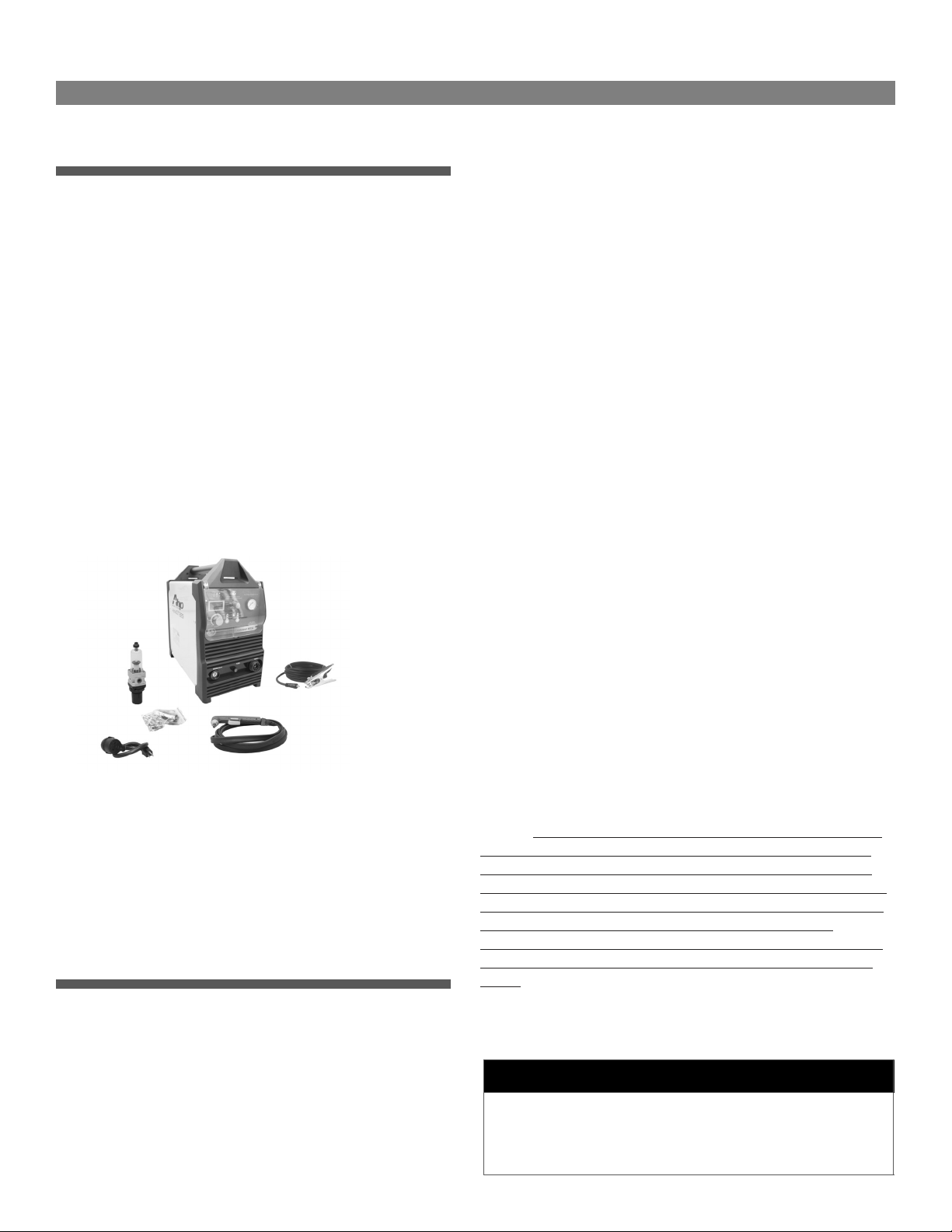
The unit comes standard with the following accessories:
• Innotect iPT 60 Plasma Torch, 14 ft.
• Work clamp and cable, 9 ft.
• Combination air pressure regulator/water trap
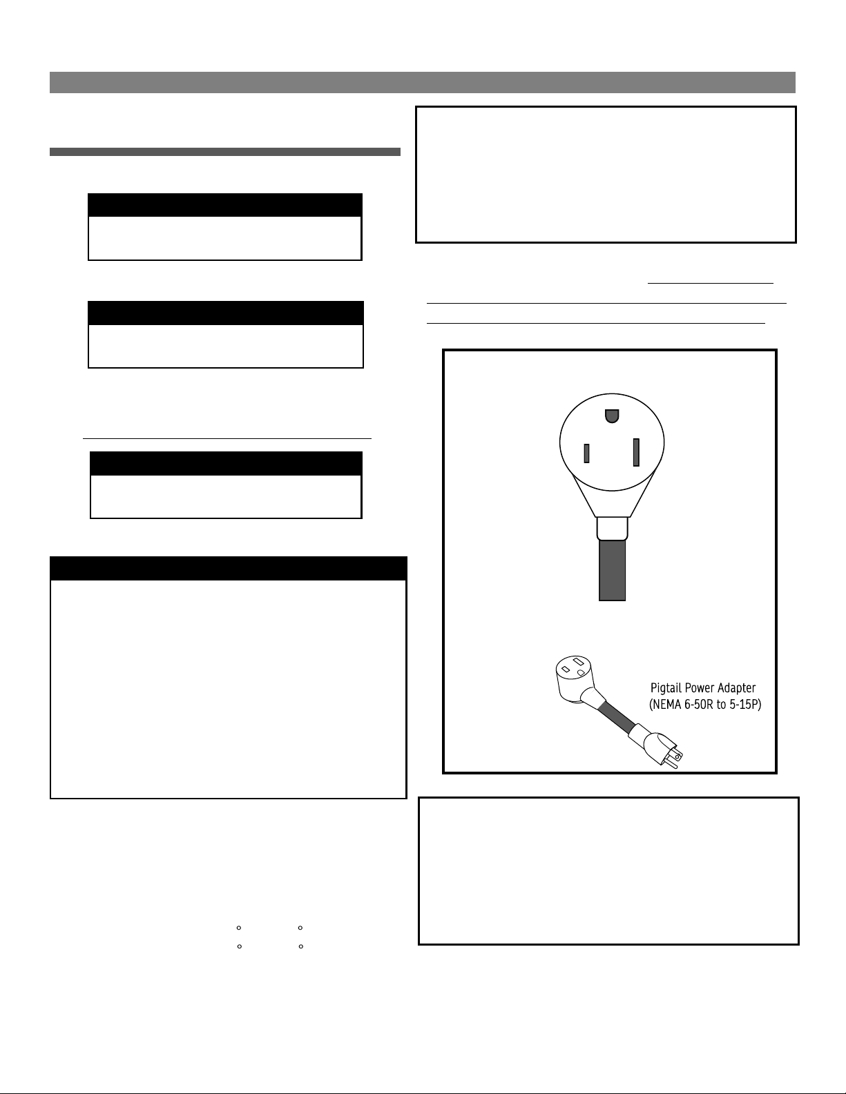
• 240 to 120V pigtail adapter
• 60A consumable starter kit
Ahp Warranty Statement
WARRANTY ONLY APPLIES TO UNITS WITH PROOF OF PURCHASE
FROM AN AUTHORIZED DEALER. NO EXCEPTIONS. PLEASE FEEL FREE
TO REQUEST A LIST OF AUTHORIZED DEALERS.
All new AHP welders and plasma cutters, shall be warrantied to the
original owner for a period to extend for 3 years from date of pur-
chase against breakage, malfunction, or other unit failure resulting
from manufacturing defect. The faulty unit will either be repaired or
an exchange will be made for a new or factory reconditioned unit at
AHP Welds discretion. The customer must contact the technical sup-
port team to review unit failure so that the warranty claim can be
established. Items such as electrodes, contact tips, nozzles, cups,
shields, liners etc, considered to be consumable items, are NOT cov-
ered under warranty. Torches, foot pedals and spool guns are warran-
tied for a period of 6 months. Additionally, certain items such as
torches, foot pedals and easily serviced parts may be individually
exchanged without returning the entire unit assembly should a fail-
ure with these items occur, at AHP Welds discretion. AHP Welds will
not be responsible for time/contract loss from unit failure, damages
occurring from improper or unskilled operation, damages resulting
from improper maintenance, improper wiring, poor quality power
sources, abuse or neglect. Nor will AHP assume responsibility for the
customer's failure to heed/read safety instructions, to read and un-
derstand operator's manual, obey occupational laws or to ensure the
unit's safe operation complies with state or local laws, personal injury
arising from the inherent risks involved with welding, including
burns, electric shock or death. Warranty extends only to the machine,
its accessories and parts contained inside as stated above. No other
warranty is expressed or implied.
In the event of unit failure or malfunction, the customer must contact
AHP to obtain a location of a designated return/repair facility. The
replacement unit will then be returned to the customer. AHP will
cover the shipping charges both ways for domestic customers that
have units in need of warranty within the first 30 days from the pur-
chase date. After the 30 days from the purchase date, the customer
shall be responsible for all shipping and handling costs both ways of
non-functioning units for repair or replacement. Customers located
outside of the USA lower 48 states will have to pay shipping and han-
dling charges both ways from the purchase date. It is the customer's
responsibility to adequately insure the unit, as AHP is not responsible
for lost or damaged returns. Labor coverage only applies if the unit is
serviced at our facility or one of our authorized dealers. We will not
reimburse the labor if the customer decides to have a third-party or
unauthorized repair technicians work on the unit.
NOTICE:
Ahp’s TIG products are designed for use by individuals with
a professional knowledge base in TIG and Stick welding and is de-
signed with commercial operation in mind. Ahp cannot be held ac-
countable for instruction and training of inexperienced users or dam-
age or malfunctions that may result from use by inexperienced users
or improper installation. If you do not have the skill level or
knowledge base to properly operate and install this machine, do not
use this machine until proper training and instruction has been re-
ceived.
View full warranty, terms of sale and shipping details here:
https://ahpwelds.com/
NOTICE:
Output on 120V will be limited to 30A. This unit is supplied with 60A consuma-
bles. To operate on 120V, you’ll need to purchase 20 or 30A rated consumables.
With a 60A consumable installed while operating on 120V, arc operation will be
erratic and unstable.. See torch page for Amp ranges of consumables.
11
Specications and Need-to-Know Information
alphaCUT 825i
Generator Operation Information
This unit may be used with any clean power rated 240V
generator with a 10,000 Surge Watt rating. Clean Power is
defined as 5% or less Total Harmonic Distortion (THD).
This means the generator produces a clean sine wave simi-
lar to what is produced by power companies. Due to the po-
tential high inrush demand (36A) while operating on 120V, operation
with 120V only generators is not recommended.
NOTICE: Operation on generators not rated by its manufacturer as a
“clean power” source is prohibited and will void the warranty. Many
manufacturers produce a version or series of their generators that
produce clean power. This is usually stated up front. If not, consult
the manufacturer of the generators to confirm THD. Clean power
generators are made in both inverter types and conventional types of
generators. Do not assume all inverter type generators produce
clean power unless the manufacturer states it. Clean power is need-
ed for most electronic equipment to prevent damage.
Duty Cycle Performance
The Duty Cycle of this machine has been established at 35% @
60A (40 C) while operating on 240V. While operating on 120V,
the duty cycle has been established at 35% @ 30A (40 C).
Duty Cycle is the amount of time, out of a solid 10 minute block of
time that the unit may operate at the rated setting. For the example
of 35% @ 60A, this means the unit may be operated up to 3.5
minutes continuously, or intermittently out of 10 minutes of time
before overheating. The balance of time remaining in the 10 minutes
(4 minutes in this example) should be while the unit is left to rest,
while continuing to run. As Amps are lowered, or as the ambient
temperature decreases below the 40 C testing benchmark, duty cycle
will increase. Lowering to just 50A the unit’s duty cycle increases to
60%. And lowering another 10A to 40A, the unit’s duty cycle increas-
es to 100%.
It is not necessary to try to keep up with the duty cycle by precisely
timing it or recording it. The unit is equipped with a thermal sensor
which will trigger an interruption of operation if the temperature has
been exceeded. Keep in mind this is not a timed feature. A duty cycle
statement is based on time welding at a particular amperage, but
because so many variables exist, and ultimately the unit’s tempera-
ture is the regulating concern, duty cycle is determined by a preset
operating temperature threshold, rather than a timed one.
If you have triggered the duty cycle interrupt on this machine, allow
the unit to cool for a full 15 minutes. The unit should automatically
reset during this time, but allow a few more minutes so the machine
can cool sufficiently so as not to overheat quickly. If it does not reset
during this time, turn the machine off and back on to reset it.
Even though this unit is equipped with a duty cycle safety feature,
intentionally and repeatedly surpassing the duty cycle will shorten
the lifespan of the unit. Routine overheating damage will usually
leave signs that can be determined during warranty repair. Damage
caused by intentional abuse of the duty cycle will not be covered un-
der warranty.
If you find that you are constantly running into duty cycle issues, it is
likely you will need a bigger machine, or need to adjust your welding
strategies to comply with the duty cycle limits of this machine.
To assure maximum lifespan of the unit, never block the cooling vents
in the rear, sides, or front. Keep the unit 16” away, on all sides, from
any obstacle to free air flow such as a wall or partition.
Required Routine Maintenance
In most places where a plasma cutter is in operation
floating and flying debris become a factor for concern.
Dust, dirt and sparks are often present in the air. The
machine will draw these contaminants in during operation
and they can be deposited inside the machine onto critical
components. These particles can conduct electricity and
create new circuit paths, not only causing poor operation, unit lock
up, but it can also cause long term damage. For this reason, the ma-
chine should be opened up and cleaned with dry, compressed air on a
regular basis: once every month in heavy use, and every 3 to 6
months under light use. If the unit remains stored most of the time,
dust still will accumulate, and this should be done at least every 6
months. When not in use, keep the machine covered. Failure to do so
constitutes neglect and may void the warranty.
To clean and service this plasma cutter:
1. Unplug the plasma cutter. Wait 10 minutes for the capacitors to
discharge. (To prevent electrical shock or electrocution.)
2. Put on a pair of safety glasses to prevent debris from blowing
into your eyes during this operation.
3. Remove the rear cover screws. Keep in mind there are 3 screws
on the bottom of the unit that hold the cover on as well. Do not
remove any other screws on the bottom.
4. Remove the rear cover and top handle.
5. Remove the steel cover screws.
6. Pull the rear cover up and to the rear while carefully watching
for wires that may catch on the louvered vents of the cover.
7. Check all wires and connections to make sure they are seated
and/or tight.
8. Use dry compressed air (or “canned” air) to blow the air off con-
nections, boards, and fittings. If the unit is particularly dirty,
unseat the affected connectors themselves, and blow out the
connections as well.
9. Reassemble the unit. Do not forget the handle!
NOTICE:
Opening the unit to clean and check connections will not
12
Specications and Need-to-Know Information
alphaCUT 825i
void the warranty. In fact it is required to maintain your in-warranty
status during the duration of your warranty. However, under no cir-
cumstances should you attempt to modify or make unauthorized
changes to the welder/plasma cutter or its programming. To do so
will void the warranty.
6
13
Specications and Need-to-Know Information
alphaCUT 825i
Cutting Gas and Setup
This unit is designed to work on straight compressed air. Your
compressor size should be a minimum of 4.5 to 5.0 CFM at 90
PSI. The minimum tank (reserve) size should be 20 gallons for
the best performance. Additionally, you will need to install a
separate air-dryer inline between the Compressor and the unit
regulator. While the regulator also serves as a water trap, this
cannot substitute for a good grade air dryer. An expensive air dryer
is not needed. There are several desiccant types that are replaceable,
or serviceable that are relatively in expensive. A refrigerated system,
while a nice feature to have, is not necessary. Dry air is key to long
service life of the consumables and torch. It also is important to
making quality cuts by hand. See the diagram below for information
concerning proper connection of the air compressor to the regulator.
Alternatively, where having compressed air is not possible, this unit
may also be used with compressed Nitrogen. You’ll need to source a
high flow regulator specifically for large volume consumption (be
sure to ask, because there are two types). While this isn’t the most
economical solution, Nitrogen cuts clean and leaves behind a good
finish. It’s perfect for using in the field where having an air compres-
sor present is not a viable option. To properly support the plasma
torch, you’ll need around 5.0 cubic feet per minute gas flow capability
of the regulator.
When in use with the air compressor, you should not adjust the com-
pressor regulator (install one if you do not have one fitted to the air
compressor) to supply more than 95 psi to the rear of the plasma
cutter. If the air pressure exceeds 95 psi supply pressure, the unit
can begin to leak internally if the unit mounted regulator is turned
wide open. It can also cause the water trap filter bowl to burst. The
regulator that is mounted to the rear of the plasma cutter is only
used to reduce the supply pressure from 90 to 95 PSI down to the
operation range of 65 to 72 psi. The absolute minimum air pressure
should never drop below 60 psi. The air pressure should remain be-
tween this range and should not change even if you are using less
Amperage.
Instead of lowering air pressure to improve arc stability,
change to a smaller diameter consumable to match the amperage
you are using. See torch page in this manual for consumable sizes
and Amp range of each size.
WARNING!
Too much supply pressure may cause the regulator to leak or the
water trap bowl to explode and cause serious injury and damage.
Never exceed 95 psi supply pressure.
CAUTION!
Do not use with an oiling system or with a worn out compressor that
may be allowing blow-by oil to seep into the air supply hose. This
may result in damage or fire. Always use a separate, clean air hose to
supply the plasma cutter to reduce chance of contamination.
NOTICE:
For best results, supply the air to the plasma cutter with 3/8” or larg-
er air hose. Do not use 1/4” supply lines.
NOTICE:
Check consumable bag for additional pieces and parts to complete
the attachment of the regulator.
1
2
3
4
0
5
Install bracket and regulator on rear of the unit.
Connect Unit to the Air Compressor
Air Dryer
Connect to rear of unit
Air tubing
Regulator
(Customer
Supplied)
This plasma cutter uses “push-to-connect” ttings to secure the air connections on
the rear of the unit. Before inserting tubing, make sure that the ends are squarely
cut or a leak may occur. To connect simply push the tubing rmly into the tting.
The small outer collar around the tting is depressed to release the tubing.
14
Specications and Need-to-Know Information
alphaCUT 825i
Connecting the Torch and Clamp
AHP uses a blow-back type of torch which eliminates the old
outdated High Frequency (HF) design that interfered with elec-
tronics and required regular maintenance. The blow-back de-
sign uses a mechanical mechanism to internally strike an arc
rather than a High voltage, High Frequency point gap design to initi-
ate the arc. The blow-back type of torch also provides a pilot arc func-
tion which keeps the arc lit, even if the cut has been lost.
The alphaCUT 825 uses a genuine Innotec iPT60 hand torch. This
torch design has become a standard torch used by multiple manufac-
turers due to it’s reliability and cut capacity with minimal arc start
delay. There are only two licensed manufacturers of this patented
design. Use genuine consumables with your torch. Be aware that
there are many knock-off manufacturers of this design. While similar
in appearance, there are significant differences in manufacturing
tolerances and even quality of copper alloys used in manufacture of
the torch and consumables. Use of consumables by knock-off manu-
facturers is discouraged as it can cause your torch to malfunction and
even short-out your machine. Torches and units that fail while using
these consumables cannot be warrantied. Purchase only direct from
AHP, or a licensed Innotec or Tecmo torch distributor. If you are not
sure, ask the supplier. Do not attempt to retrofit this unit with anoth-
er torch type or brand. The dynamics of a plasma cutter are such that
the individual plasma cutter and torch must work perfectly together
or a failure may result. Arc initiation must be perfectly timed be-
tween the torch and the unit. Additionally the internal design of the
torch establishes the arc voltage. Other types of torches will not oper-
ate (if they do at all) well with this unit and will cause premature
failures and wear on the unit. Use with other types or brands of plas-
ma cutters will void the warranty.
The connector used on the torch is the Central connector, which is
another design commonly used by several manufacturers. This al-
lows rapid, secure connection of the torch. It also allows the unit to
be easily broken down and conveniently stored without tools to re-
move the torch.
Similarly, the work clamp and DINSE 25 type connector are commonly
used on plasma cutters of this size. The 200A rating of the clamp is
more than sufficient to carry the power of the cutter. However, occa-
sionally a work clamp may wear out or fail. Replace it with a work
clamp rated for 200A or above. These can be found at any reputable
welding supply store. The DINSE 25 type connector is a common
connector used in the industry and may be also be sourced at most
welding supply stores. This connector can be re-used however if it
has not been damaged. To remove the cable from the connector,
remove the rubber cover from the brass base of the connector by
firmly pulling them apart while wiggling the rubber cover back and
forth slightly. The rubber will pop back to reveal the set screws that
hold the cable. The set screws can be loosened and the cable then
removed for replacement. If the cable is being replaced, do not allow
the work clamp cable length to exceed the length of the torch.
NOTICE: With use, these screws may loosen up due to fatigue or wear
of the cable. If irregular operation is observed, check the set screw
tightness before progressing to other possible causes.
Pilot Arc Operation
The Pilot arc is designed to sustain an arc when there is no
continuity sensed to the work. The pilot arc is a low amperage
arc that is created and sustained by the torch itself and is not
designed for cutting. This is due to the fact that the circuit
path is established back through the torch and to the unit and
is carried on the consumable face. It is designed to lightly scour the
surface to burn off scale or paint that may interfere with continuity.
It also is designed to sustain the arc when continuity is lost so that
the torch will not have to be retriggered. When continuity is lost the
unit switches over to the pilot arc. When continuity is regained, it
seamlessly transitions back to the cutting arc out. In auto restart
Work Clamp
All Power Adapters are DINSE 25 Series Type (3/8” nominal diameter). This is the
smaller type rated for up to 200A output.. The Torch connector is a Central Euro-
Connector used by several brands which allows easy removal of the torch.
DINSE 25mm2 Connector
Central Connector
Innotec iPT60 Torch
Fuse
15
Specications and Need-to-Know Information
alphaCUT 825i
mode, the pilot arc is able to switch back and forth as needed contin-
uously. However, the downside to the auto restart mode of the pilot
arc is that the pilot arc increases wear on the consumable since the
arc is carried by the consumable itself and erodes faster than normal
cutting would. In the tip saver mode, the arc will go out after three
seconds if the arc is not started. The pilot arc will not relight and the
torch much be retriggered. This helps to manage consumable life
and make the user more conscious of abusing the pilot arc.
When the pilot arc is engaged, the amperage in the display will drop
to around 25 to 27 Amps. This is normal since the consumable itself
becomes the current path and the arc is maintained on the consuma-
ble face. If it were to transfer at 60 Amps, it would quickly destroy
the consumable. This also serves as a diagnostic if the unit is not
cutting properly. If it is only registering pilot arc Amperage despite
being set higher, check the work clamp connection. Make sure it is
free of rust and paint and is directly mounted to the piece being cut.
If the work clamp is damaged or becomes hot, or the cable becomes
hot while cutting. Check and replace the work clamp. Remove the
rubber boot on the DINSE connector and check for tightness of the
work clamp cable..
Getting Started Cutting
The unit is easy operate, with a minimum amount of knowledge and
setup required. The functions of the machine are basic and are
straight forward in adjustment.
This machine uses a breaker style power switch located on the rear.
This is used to turn the unit on and off. There is no other switch, so
be sure to mount your plasma cutter where you can access the rear of
the unit to switch it on and off.
You’ll also notice that there is a bolt located on the lower rear of the
machine. This is to provide an additional ground point, grounded
direct to a ground rod driven outside the shop area. This is to be used
only in case of electromagnetic interference from the operation of the
inverter. This is not normally needed and it is rare to have interfer-
ence. But, if interference is suspected, consult an electrician for
proper use and wiring of this additional grounding point. If this
point is needed, all other metal structures, inside the shop and in-
cluding the shop will have to be grounded to separate ground rods
every few feet. If interference cannot be remedied by moving the unit
to a different location, then consult with a locally licensed electrician
to determine the best course of action. Additionally, you may also
call AHP for more information if it is needed.
Before turning on the unit, connect the air line and make sure no
more than 95 psi is supplied to the rear of the unit. Next connect the
work clamp direct to the work. Then turn the unit on. If the air pres-
NOTICE:
This unit is not designed for gouging. Do not attempt gouging
type of operations with this unit. Gouging stretches the arc too
far and will cause the voltage to exceed design parameters.
CAUTION:
Continual use of the pilot arc will over heat the pilot arc circuit and
can damage the system. Do not try to cut without the work clamp
attached. This is not designed to be used for etching or marking
purposes. Make sure the work clamp is connected directly to the
part being cut at all times while the unit is in use. Remove all mill
scale and paint at the point where the work clamp is to be at-
tached. Occasionally, through routine use, the pilot arc fuse will
blow. There are extra fuses included with the consumable kit.
These are common “Buss” type fuses and can be gotten at most
automotive supply stores. The part number and Amp rating is
stamped on one of the metal fuse ends. Do not use a higher rated
fuse or you may damage your unit and/cause a fire.
Gas Inlet
Power Switch
Power Cable with Plug
(NEMA 6-50P)
Ground BoltAir Inlet
Regulator
(Installed)
16
Specications and Need-to-Know Information
alphaCUT 825i
sure is not sufficient to operate, the warning light will come on and
prevent cutting to protect the torch and consumables. To adjust the
air pressure, nce the unit is turned on, pull up on the regulator knob.
You will hear and feel a slight click and the regulator knob will move
up slightly, allowing you to adjust the air pressure. Twist it slowly
clockwise to raise the pressure and then twist it slowly counter-
clockwise to decrease the pressure. Once the air pressure in the
front gauge reads 60 psi, then press and hold the air check button
and adjust the air pressure to 72 psi. Once the air pressure is adjust-
ed, release the Air check button. The pressure may spike slightly
about 3 to 4 psi. This is normal. If it spikes more than that, you’ll
need to increase your supply air hose diameter or reduce the length
of the hose. A large pressure differential between the air flowing and
when it is static is often due to improperly sized (or kinked) supply
hose. While not necessarily a big issue, it can make adjusting and
maintaining a consistent air pressure while cutting more difficult.
Once air pressure is correctly set between 65 and 75 psi while flow-
ing, select Auto Restart and Trigger unlock using the buttons. Next,
set post flow at 15 Seconds. Last, make sure your amps are set be-
tween 50 and 60A. Once you have this correct, the unit is ready to
use. But before using, once again confirm that the work clamp is
connected securely connected to the part being cut.
When you are fully ready to cut, please note that the iPT60 torch does
come with a stand-off guide. This stand-off may be removed if you are
more comfortable cutting free hand or need to make intricate design
cuts. However, it is not recommended to drag cut with this unit un-
less special shielded drag consumables are sourced for the torch.
Currently AHP does not offer shielded drag consumables direct. How-
ever, these are available from OEM suppliers of iPT/PT 60 torches and
their consumables The standoff is handy for making long, straight
guided cuts since the leg of the stand-off can glide against a straight
edge used for a guide. It can also be used in multi-directional cutting
with a light touch and a little practice.
The unit has been supplied with 50 to 60A range consumables. While
using lower amperages, you will need to use consumables that are
rated for lesser Amp cuts. These consumables have smaller diameter
orifices. Always keep the pressure within the operating range of 60
to 72 PSI, with 65 to 72 PSI being considered ideal. Don’t try to low-
er air pressure to get the consumable to provide a steady arc. While
air pressure can be fine tuned within the range for best cut perfor-
mance, change consumables first to match the Amp range. Use the
guide below and the iPT 60 torch parts pages to help you determine
the correct settings for your plasma cutter.
Cut Recommendations*
*Practically all metal can be cut with the stock consumables that are
included with the starter consumable kit as long as the cuts are kept
between the 50 and 60A range. The main difference is that the higher
Amp cuts result in a more rapid cut speed and wider kerf width, which
may reduce cut quality on the thinnest materials. The figures given
above are only given as general capability with the best cut quality in
mind. For practical purposes, 60A can cut metal plate 1/4” and above
with reasonable quality. For Aluminum and Stainless Steel cuts, de-
crease cut thickness capability ratings by 30%.
See the next page for more detailed explanation of the panel features
and functions.
Use the cutting information on pages 18-21 to assist you in learning
how to cut with this unit.
Cut Thickness* Suggested Amps Consumable Size
≤ 1/8” 20-25A .6mm
1/8” to 1/4” 25-30A .8mm
1/4” to 3/8” 30-40A .9mm
3/8” to 1/2” 40-50A 1.0mm
≥ 1/2” 50 to 60A 1.1mm
60
17
Control Panel Features
Component Identication and Explanation of Function
alphaCUT 825i
1
2
3
456
7
8
Control Panel Features
1. Power Indicator, Warning Light and Pressure OK LED. The left LED Power Indicator will remain on while the switch is turned on, if power is being supplied. If the
middle warning light comes on during use, then check the error code provided to help determine whether it is an over current or duty cycle issue. If it is a duty cycle
issue, allow the unit to continue to run, without welding for 15 minutes. The unit will automatically reset. If the code is an over-current issue, then switch the unit off and
check the cause. The unit may not clear the code when it is switched back on, or may instantly display again when welding is attempted. In this case, immediately switch
the unit off and contact Ahp tech support as soon a practically possible. Do not attempt to weld or allow the unit to continue to run if an over current has occurred.. The
right LED is the lit once the unit reaches minimum safe cutting pressure around 50 psi. This is not the recommended cut pressure. It only serves to help prevent damage
if the air supply line is not connected or the air pressure drops too low. If the Pressure-OK LED is no longer lit, the unit will continue to idle, but cutting output will be
interrupted. This light must be on to resume cutting. If the LED does not illuminate after correcting the air pressure, contact AHP.
2. Amp Display. This displays the cutting Amps. In case of an over current or duty cycle event, this will display an error code.
3. Amp Control Knob. The Amp control knob adjusts the Amperage from 20 to 60A while operating on a 240V power supply. While operating on a 120V power supply, the
Amps will range from 20 to 30A.
4. Auto Restart/Tip Saver. For normal operation, select Auto Restart. This allows the cutter to switch seamlessly back and forth between the cutting arc and pilot while
the trigger is continued to be held down if continuity is lost. These type applications would include cutting on perforated or expanded metal. It also helps for uneven
surfaces or where paint and/or rust are heavy. The TIP saver function works best on long, even cuts. The arc will go out if the trigger is held down and no continuity is
sensed. It will also time out if cutting is not started within 3 seconds of triggering. To restart the arc in TIP saver mode, the user must release the trigger and allow the
cutter to reset before retriggering. This can take several seconds.
5. Trigger Unlock/Trigger Lock. The Trigger lock function is designed for long cuts to remove fatigue. The lock function causes the trigger to go into a 4 step mode.
When engaged, the trigger must be pressed and released slowly to start the cut. The arc will stay on without holding the trigger down. To stop the arc, the trigger is
pressed and released slowly to stop cutting and to begin the post flow cycle. The trigger unlock function is a 2 step process. To start and continue the arc, simply press
and hold the trigger. To stop cutting and begin the post flow cycle, release the trigger.
6. Normal/Air Check. The Air check function is only used during the setup process to help adjust the cutting pressure. The cutting pressure can only be accurately
adjusted while the air is flowing. The normal operation is the default mode.
7. Air Pressure Gauge. The air pressure gauge indicates the cutting pressure, not the supplied pressure to the rear of the unit. The air compressor gauge should be used
to indicate supplied pressure. Cutting air pressure should be maintained between 65 and 72 PSI for optimum cutting. Minimum cutting pressure should be no less than
60 PSI.
8. Post Flow. The Post-Flow is adjustable between 0 and 60 Seconds. This is the amount of time the air will flow after the cutting stops. Some post flow should always be
maintained. Post-Flow is designed to provide cooling to the torch and consumables. The amount needed is dependent upon both the Amperage used and the length of
time the cutting takes place. For best results set post flow for a minimum of 15 seconds for most cuts.
60
18
Component Identication and Explanation of Function
alphaCUT 825i
NOTICE:
The design of the blow back start may cause a slight delay in the arc as the air pressure must built inside the torch tubing
and head to create the pressure needed to force the electrode off the nozzle seat. This may take up to a second, especial-
ly when using longer torches or marginal air supply systems. Restarting the arc in tip saver mode requires retriggering
the torch. If the torch does not light after 3 seconds, let go of the trigger and press it again. If the start or arc is erratic
check nozzle and electrode for tightness and wear.
0°-15°
TRAVEL
1/16”-1/8”
EDGE START
40°-60°
TRAVEL
1
PIERCE START
2
3
IMPORTANT:
If you use the standoff guide provided with the torch, it must be adjusted to provide no more than 1/8” standoff, less if possible. Long
standoff heights reduce cut capacity and quality. It also promotes rapid consumable wear and can prevent the pilot arc from transferring.
EDGE STARTS
Edge starts are the best type of start to promote consumable
and torch life. This reduces blow back of molten material and
allows a smooth gradual start of the arc and maximizes cutting
capacity.
1) Line up the hole on the tip of the electrode on the edge
of the cut. Hold torch perpendicular to the cut initially,
about 1/16” off the metal. Slide the yellow safety lock
and squeeze the trigger. Wait for arc to start.
2) Once the arc starts, wait for the arc to penetrate all the
way through the metal.
3) As the torch penetrates the flame all the way through
the metal, tilt the torch so there is a slight lead in the
flame if metal is thin. If the metal being cut is thick,
keep holding torch in a nearly vertical position.
4) Begin moving the torch in the direction of the cut.
Maintain 1/16” to 1/8” standoff height.
5) Move the torch fast enough so the sparks and flame trail
from the bottom edge at an angle of no more than 30°
and no less than 10° from perpendicular to the metal.
Excess angle of sparks/flame indicate too fast of travel
speed or practical cut capacity has been reached. Little
or no angle indicates too slow of travel speed.
PIERCE STARTS
Piercing starts often result in rapid consumable wear and
excess blow back of molten metal deposited onto torch and
consumables. This should be done only as necessary on thicker
material.
1) Tilt the torch in the direction of travel or toward the
side of the metal to be discarded or wasted at a 40° to
60° angle. Slide the yellow safety lock and squeeze the
trigger. Wait for arc to start and transfer to the metal.
2) As the flame penetrates through the metal (at a sloped
angle) rotate the torch slowly to the vertical position. Tilt
the torch from 0°-15° for thin metal cuts, or hold it nearly
perpendicular for thicker metal cuts.
3) Begin moving the torch in the direction of the cut. Main-
tain 1/16” to 1/8” standoff height.
4) Move the torch fast enough so the sparks and flame trail
from the bottom edge at an angle of no more than 30°
and no less than 10° from perpendicular to the metal.
Excess angle of sparks/flame indicate too fast of travel
speed or practical cut capacity has been reached. Little
or no angle indicates too slow of travel speed.
19
Component Identication and Explanation of Function
alphaCUT 825i
TRAVEL
FLAME AT FAST TRAVEL SPEED
TRAVEL
FLAME AT SLOW TRAVEL SPEED
TRAVEL
FLAME AT NORMAL TRAVEL SPEED
IMPORTANT:
Check consumables regularly for wear and change them out before they are completely worn out. A good practice is to check consumables before turning
the machine on each time you go to cut. It takes only a few seconds and can save yourself a lot of extra effort later. Allowing the consumables to wear until
they quit working may damage torch related components, creating a more costly repair. Periodically, with the unit turned off, check the spring action of the
electrode by removing the cup and tip and pushing your thumb or finger down on the electrode. The electrode should depress slightly and spring back
quickly without a delay. If it does not, the torch head may need to be disassembled, cleaned and lightly lubricated with di-electric grease. In some cases the
sealing O-rings may be broken or dirty causing sticking. Replacement torch head kits are available if repair is not an option. Sticking of the electrode like
this causes starting issues. Most often this condition occurs because of moisture and dirt that makes it way into the system. Additionally, do not overtight-
en the electrode or overheat the torch (by poor cutting techniques such as excessive piercing starts on thick metal) or the electrode threads may gall in the
torch head and break off during removal. This usually occurs on lower quality consumables (non-OEM) with poor chrome plating, but can occur if OEM con-
sumables are overtightened.
NOTE:
When stepping down amps to cut thinner material, you must change to smaller orifice nozzle. Nozzles are offered in different sizes which are made for dif-
ferent amp levels. See the torch parts page for amp range and size of consumables. AHP offers OEM size and configuration of consumables originally sup-
plied with the torch for replacements and do not offer all configurations or sizes. OEM suppliers of the Innotec iPT torches (local and online) offer extended
range of sizes and configurations. An orifice that is too large for the amps being used will result in arc instability and a rough cut. Do not attempt to lower
air pressure to compensate as this makes the issue worse.
NOTICE:
For longer consumable life do not use the pilot arc unnecessarily. For expanded metal cutting be sure to select “Auto
Restart” to re-fire the pilot arc automatically. For long, uninterrupted cuts, select the “Tip Saver Start” feature and do not
fire the torch unless you are near the metal and ready to cut.
20
Component Identication and Explanation of Function
alphaCUT 825i
MINIMAL EASY TO CLEAN DROSS
RESULTS OF CUT AT CORRECT SPEED
NOTICEABLE SMALL, HARD DROSS
RESULTS OF CUT AT FAST SPEED
SIGNIFICANT SOFT, POROUS DROSS
RESULTS OF CUT AT SLOW SPEED
VERTICAL CUT LINES
RESULTS OF TOO MUCH CURRENT OR TOO MUCH
STAND OFF HEIGHT
(SIDE VIEW)
MELTED TOP EDGE
RESULTS OF WORN CONSUMABLE OR LOW AIR
PRESSURE
(SIDE VIEW)
SEVERLY ANGLED CUT AT TOP
SMOOTH, EVEN CUT LINES WITH A S REARWARD SWEEP ROUGH, DISTINCT CUT LINES SPACED FAR APART

Other AHP Welding System manuals

AHP alphaTIG 225Xi User manual

AHP

AHP alphaTIG 225Xi User manual

AHP alphaMIG 231ms User manual

AHP

AHP alphaMIG 231ms User manual

AHP ALPHA-CUT60 User manual

AHP

AHP ALPHA-CUT60 User manual

AHP alphaMIG 190MP User manual

AHP

AHP alphaMIG 190MP User manual

Popular Welding System manuals by other brands

EWM TIG 260 F1 WD 5P operating instructions

EWM

EWM TIG 260 F1 WD 5P operating instructions

Walter Surfox Mini user guide

Walter

Walter Surfox Mini user guide

Migatronic ZETA 40 instruction manual

Migatronic

Migatronic ZETA 40 instruction manual

Hypertherm powermax900 Operator's manual

Hypertherm

Hypertherm powermax900 Operator's manual

HURNER HST-S-160 user manual

HURNER

HURNER HST-S-160 user manual

Onan BF Series Operator's/Service Manual and Parts Catalog

Onan

Onan BF Series Operator's/Service Manual and Parts Catalog

Thermal Arc FABRICATOR 210 owner's manual

Thermal Arc

Thermal Arc FABRICATOR 210 owner's manual

Miller Syncrowave 250 DX owner's manual

Miller

Miller Syncrowave 250 DX owner's manual

Telwin SUPERIOR PLASMA 160 instruction manual

Telwin

Telwin SUPERIOR PLASMA 160 instruction manual

Draper MI200A Original instructions

Draper

Draper MI200A Original instructions

Meec tools MIG 130 A operating instructions

Meec tools

Meec tools MIG 130 A operating instructions

Kühtreiber FENIX 160 operation instruction

Kühtreiber

Kühtreiber FENIX 160 operation instruction

Weldclass WeldForce WF-140ST operating instructions

Weldclass

Weldclass WeldForce WF-140ST operating instructions

CIGWELD 170 HF operating manual

CIGWELD

CIGWELD 170 HF operating manual

Opticon MIG 100E user manual

Opticon

Opticon MIG 100E user manual

Soyer SRM EcoWeld BMK-20i operating instructions

Soyer

Soyer SRM EcoWeld BMK-20i operating instructions

Hitbox ARC160D operation instruction

Hitbox

Hitbox ARC160D operation instruction

Stark 55010 Owner's manual and safety instructions

Stark

Stark 55010 Owner's manual and safety instructions

manuals.online logo
manuals.online logoBrands
  • About & Mission
  • Contact us
  • Privacy Policy
  • Terms and Conditions

Copyright 2025 Manuals.Online. All Rights Reserved.