9
Specications and Need-to-Know Information
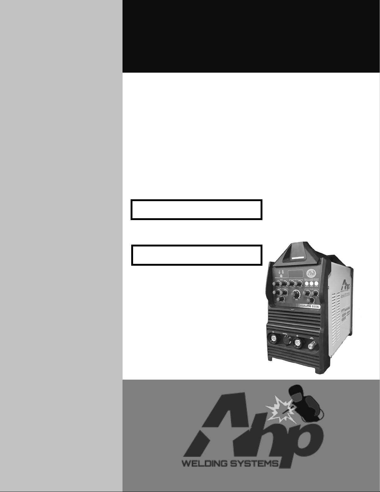
alphaTIG 225Xi
About the AlphaTIG 225Xi
The AlphaTIG 225Xi is the latest evolution of the long running Al-
phaTIG series. It utilizes the latest in digitally controlled IGBT invert-
er welding technology, while providing the user with a mostly manual
interface. This unit is great for users who tend to use a few different
settings and like to be able to see and determine their settings at a
glance, but who still desire the simplicity and reliability of a internal
digital design.
The unit comes standard with the following features:
• Dual Voltage 120/240V operation capability
• 225A AC and DC TIG output for welding all metals
• 185A AC and DC Stick output
• TIG AC Frequency adjustment
• TIG AC Balance adjustment
• 2T/4T Torch switch operation capability
• Foot Pedal operation
• HF or Lift Start Modes for TIG arc starting
• AC and DC Pulse in TIG mode
• 10 Amp DC minimum start
• 20 Amp AC minimum start
• Water Cooler Plug in the rear
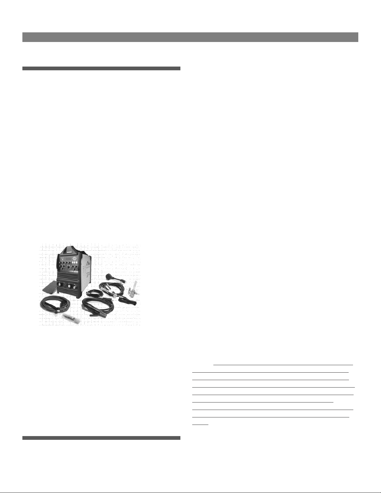
The unit comes standard with the following accessories:
• Nova Long Life Foot Pedal (Low Profile)
• 26 Series Gas-Cooled TIG torch,12.5 ft cable, 35-70 DINSE style
adapter
• Basic consumable kit for TIG torch (Tungsten not included)
• Billet Brass Floating Ball type regulator
• Stick Electrode holder, 9 ft cable, 35-70 DINSE style adapter
• 2T/4T torch switch
• 250A Work Clamp, 6 ft cable, 35-70 DINSE style adapter
• 240V to 120V step down power cord pig-tail adapter
Ahp Warranty Statement
WARRANTY ONLY APPLIES TO UNITS WITH PROOF OF PURCHASE
FROM AN AUTHORIZED DEALER. NO EXCEPTIONS. PLEASE FEEL FREE
TO REQUEST A LIST OF AUTHORIZED DEALERS.
All new AHP welders, shall be warrantied to the original owner for a
period to extend for 3 years from date of purchase against breakage,
malfunction, or other unit failure resulting from manufacturing de-
fect. The faulty unit will either be repaired or an exchange will be
made for a new or factory reconditioned unit at AHP Welds discretion.
The customer must contact the technical support team to review unit
failure so that the warranty claim can be established. Items such as
electrodes, contact tips, nozzles, cups, shields, liners etc, considered
to be consumable items, are NOT covered under warranty. Torches,
foot pedals and spool guns are warrantied for a period of 6 months.
Additionally, certain items such as torches, foot pedals and easily
serviced parts may be individually exchanged without returning the
entire unit assembly should a failure with these items occur, at AHP
Welds discretion. AHP Welds will not be responsible for time/contract
loss from unit failure, damages occurring from improper or unskilled
operation, damages resulting from improper maintenance, improper
wiring, poor quality power sources, abuse or neglect. Nor will AHP
assume responsibility for the customer's failure to heed/read safety
instructions, to read and understand operator's manual, obey occupa-
tional laws or to ensure the unit's safe operation complies with state
or local laws, personal injury arising from the inherent risks involved
with welding, including burns, electric shock or death. Warranty ex-
tends only to the machine, its accessories and parts contained inside
as stated above. No other warranty is expressed or implied.
In the event of unit failure or malfunction, the customer must contact
AHP to obtain a location of a designated return/repair facility. The
replacement unit will then be returned to the customer. AHP will
cover the shipping charges both ways for domestic customers that
have units in need of warranty within the first 30 days from the pur-
chase date. After the 30 days from the purchase date, the customer
shall be responsible for all shipping and handling costs both ways of
non-functioning units for repair or replacement. Customers located
outside of the USA lower 48 states will have to pay shipping and han-
dling charges both ways from the purchase date. It is the customer's
responsibility to adequately insure the unit, as AHP is not responsible
for lost or damaged returns. Labor coverage only applies if the unit is
serviced at our facility or one of our authorized dealers. We will not
reimburse the labor if the customer decides to have a third-party or
unauthorized repair technicians work on the unit.
NOTICE:
Ahp’s TIG products are designed for use by individuals with
a professional knowledge base in TIG and Stick welding and is de-
signed with commercial operation in mind. Ahp cannot be held ac-
countable for instruction and training of inexperienced users or dam-
age or malfunctions that may result from use by inexperienced users
or improper installation. If you do not have the skill level or
knowledge base to properly operate and install this machine, do not
use this machine until proper training and instruction has been re-
ceived.
View full warranty, terms of sale and shipping details here:
https://ahpwelds.com/