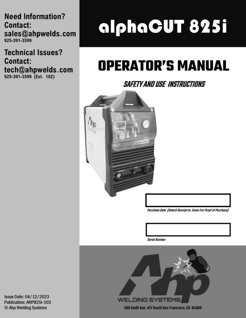
AHP ALPHA-CUT60 User manual

PLASMA CUTTER
OWNER'S MANUAL
MODEL:ALPHA-CUT60
(INVERTER POWERED PLASMA CUTTING POWER SUPPLY)

1
PRODUCTS INTRODUCTION
Congratulations on your purchase.
OUR ALPHA-CUT60 UTILIZES THE LATEST INVERTER TECHNOLOGY
50Hz/60Hz frequency is inverted to high frequency (the converted is over 100KHz) which
then reduces the voltage and commute current. The inverter power supply generates a
powerful DC welding current through PWM technology. Inverter technology helps in both
reducing the size and weight of the power source in addition to being cost effective to
operate. It also allows a smoother, more consistent power source over conventional
transformer units (efficiency is increased by 30%).
The ALPHA CUT 60 uses non HF cutting technology. A blowback style torch is used to
allow for easy cutting through rusted /painted surfaces without having to clean the surface
prior to being able to start the cutting arc as other HF ONLY models require.
Adjustable post flow allows cooling of the torch tips which in turn gives a longer
consumable life.
Some of the characteristics of our ALPHA -Cut are as follows
1. Stable power output
2. Reliability
3. Lightweight
4. Efficient Energy-saving
5. Minimaloperating noise
6. High cutting speed
7. Clean cuts and very little dross with minimal cleaning for welding on the cut edges.
Our Plasma cutter can be used on a wide variety of conductive materials and it is suitable for
cutting Stainless Steel, alloy steel, mild steel, copper and other metal materials.

2

3

4
The panel picture above is for reference only and subject to change.

5
INSTALLATION
Input cable connection (Refer to previous diagram)
1. Every machine has been supplied with the relevant voltage connecting plug. The power
cable must be connected to the correct power source for either plug: 110v uses pigtail
adaptor plug supplies, 220v uses plug already attached on power cord end. If the Plasma
Cutter is connected to a 220v Power source using a 110v plug or if the 220v power plug
is connected to 110v this may cause damage to the unit.
2. Make sure power cable is connected to power receptacle securely, to eliminate any
arcing or oxidization.
3. Do not operate on a generator that does not have a clean sine wave and stable power
output. Spiking on voltage output can cause damage to components in the Plasma cutter.
Output cable connection
1. Air input line needs to be securely pushed into the quick connect fitting so as to prevent
any air leaks.
2. The plasma torch connecting nut is supplied with a plastic cover. Slip this over the nut
and securely thread this into the output connection on the front panel using your fingers.
Do not overtighten the connection as it can cause damage.
3. Connect the terminal ring eye wire to the pilot arc grounding screw beside the plasma
torch connection. Then, connect the 2 pin Amphenolplug for the trigger control. Finally
connect the work lead (Ground clamp) connection to the red dinse connection.
CHECK
1. Check if the plasma cutter is grounded reliably according to local standards. If used on
standard breaker panel box the ground wire and panel should be already grounded
according to your local code.
2. Check if all connectors are firmly connected.
3. Check if power voltage is correct.
OPERATION
Turn the power switch to the “on” position. At this time, indicator light will be ON showing
unit is powered on.
1. Adjust the air (gas) pressure and set to between 55 to 75psi.
2. Press the torch trigger and you should have a plasma arc from the tip. Caution: the
plasma arc can cause extreme burns, keep tip away from your body at all times.
3. Set the amps to your required cutting thickness.
4. Keep tip approximately 1/8" from workpiece and move the tip as you see the cutting arc
below the workpiece showing you that the cut is completely through the metal. Move
the torch in a smooth continuous motion for best cutting results.

6
NOTE:
OPERATION ENVIRONMENT
1. The Plasma cutter can perform in temperatures between –10 and +40 degrees centigrade
with a maximum dampness level of 80%.
2. Avoid operating with the sun directly on the unit as this will increase the inside
temperature and decrease duty cycle.
3. Keep machine dry and stored or use in a dry location out of the elements.
4. Do not use the Plasma cutter in environments that have a high concentration of dust or
corrosive gas in the air.
SAFETY
1. Make sure the work area is adequately ventilated.
The Plasma cutter is supplied with two Axial-flow fans to cool both upper and lower
heat sinks and boards.
NOTES: Exhaust and Intake vents must be clear of any obstructions in order to allow
the Plasma cutter to adequately get air flow for cooling. A minimum of twelve inches is
required for air flow to and from all vents.
2. Correct voltage must be used for all amp settings either on 110v or 220v the voltage
drop cannot go lower than 105 volts on 110v or 210 volts on 220v
Do not exceed load or operate at maximum duty cycle on a constant basis as this will
shorten the life of various internal components.
3. Voltage Range
The power voltage range of the plasma cutter is shown on the technical data page.
Automatic voltage compensation circuits will help prevent the unit from exceeding
the allowable range. However, if the input voltage is too high, it could damage
components.
4. A grounding bolt is marked GROUND on the back panel. This is primarily used when
running an approved clean power generator using a grounding rod driven into the
ground and then connected by a wire cable to the ground bolt on the unit.
Make sure when using the grounding rod that it is grounded reliably by a cable whose
section is 6 square millimeter in order to prevent from leaking,feedback and
electrostatic shock.

7
5. Thermal overload sensors will switch on if the unit exceeds the duty cycle. Fans will
continue to run but no power is available. Once the unit is cooled down, the power
switch can be turned OFF and then back ON to continue cutting. Powering the unit OFF
and ON resets the thermal overload switch. The red O.C. overload light appears when
the Plasma cutter hits the duty cycle.
CUTTING NOTES
1. When cutting thinner material, up to 2 to 3 mm, you can drag tip the torch and the
cutting tip can touch the material as you cut. For thicker materials it is recommended
that a distance of 3 mm (1/16' to 1/8’) distance be kept from the cutting surface. This not
only gives better consumable life but it increases cut quality.
2. The Work piece clamp or grounding clamp must be placed on a clean section of metal,
as close as possible to the cutting area in order to have a good ground and maximum
efficiency. If the ground is bad, problems will arise with poor cutting quality and loss of
cutting arc.
MAINTENANCE AND TROUBLE SHOOTING
Maintenance
1. Regularly remove dust by using compressed air. If the Plasma cutter is used or stored in a dusty
environment where a high volume of dust, smoke or metal particles accumulate,periodically
remove the casing and carefully clean the interior using compressed air. It is important to avoid
blasting high volume air directly onto the smaller wired connections or electrical components.
In environments where dirt, smoke or dust is accumulating daily, the Plasma cutter must be
cleaned daily.
2. Ensure the Plasma Cutter air pressure is set adequately in order to protect smaller or delicate
components.
3. Check all electrical connections and make sure the connectors are in place and firmly tightened.
4. Avoid allowing any moisture to enter the unit. If the unit is damp, it must not be powered ON.
5. The Plasma cutter must be totally dry before attempting to use it.
6. If the plasma Cutter is to be stored, place it in a clean dry environment, preferably packaged in the
original box.

8
Trouble Shooting
ISSUES
1) Switch indicator is on, fan is not working Over voltage protection is in effect. Turn off machine for
several minutes, then turn on again.
2) Switch indicator is lit and fan is working.
However, when control knob of torch is activated,
there is no arc-striking sound and
electromagnetic valve is not working.
Check if torch is open circuit.
Check if control knob of torch is damaged.
It may be that part of assistant power of top board
is damaged and there is no DC 24V output.
3) Switch indicator is lit and fan is working.
However, when control knob of torch is
activated, there is no arc-striking sound and
interior red diode light is on.
Check if MOS FMH23N50E chips on top board
are damaged(driver module is damaged )
Step up transformer on bottom board is damaged
Control module is damaged
4) Switch indicator is lit and fan and
electromagnetic solenoid valve areworking,
however, the interior red diode is not lit.
There is an issue with the pilot arc start transfer to cutting
voltage:
Tip is too far from the workpiece
Check if any of the four voltage rectifier diodes
are damaged
5) All operations of the plasma cutter are normal
but no arc is produced.
Input voltage is too low.
Air pressure from compressor is either too high or too
low.

9
AHP WELDS 3 YEAR WARRANTY
All new AHP welders shall be warrantied to the original owner from date of
purchase, for a period of 3 years,against breakage, malfunction or other unit
failure resulting from manufacture defect. The faulty unit will either be
repaired or an exchange will be made for a new or factory reconditioned unit
at AHP Welds discretion. The customer must contact the technical support
team to review unit failure so that the warranty claim can be established.
Items such as electrodes, contact tips, nozzles, cups, shields, liners etc,
considered to be consumable items, are NOT covered under warranty.
Torches, foot pedals and spool guns are warrantied for a period of 6 months.
Additionally, certain items such as torches, foot pedals and easily serviced
parts may be individually exchanged without returning the entire unit
assembly should a failure with these items occur, at AHP Welds discretion.
AHP Welds will not be responsible for time/contract loss from unit failure,
damages occurring from improper or unskilled operation, damages resulting
from improper maintenance, improper wiring, poor quality power sources,
abuse or neglect. Nor will AHP assume responsibility for the customer's
failure to heed/read safety instructions, to read and understand operator's
manual, obey occupational laws or to ensure the unit's safe operation
complies with state or local laws, personal injury arising from the inherent
risks involved with welding, including burns, electric shock or death.
Warranty extends only to the machine, its accessories and parts contained
inside as stated above. No other warranty is expressed or implied. For
complete warranty please visit:
http://www.ahpwelds.com/return_warranty.php
To register you unit for warranty please visit:
http://www.ahpwelds.com/product_registration.php
Contact info:
[email protected] (warranty)
Sales 925- 391- 2021
Support 925 – 391-3583

10
Table of contents
Other AHP Welding System manuals