Air Fantastic CAP3000 User manual

Central Air Purier (CAP)
Owner’s Manual
For use with Models:
CAP3000, CAP5000
For safety and to ensure proper use carefully read
the contents of this manual before operating or
installing the unit.
Air Fantastic

Thank You for Choosing Air Fantastic®CAP system!
Congratulations, you own the most advanced induct air purier available! Before
operating the CAP System please read this manual in its entirety. Doing so will
give you important information to keep you safe from harm and ensure you get
the most benets from your System. For additional information please contact us:
Mail: Air Fantastic, LLC
Attn: Customer Service
4406 Eagles Landing Dr.
Austin, TX 78735
Web: www.airfantastic.com
E-mail: [email protected]
Phone: 1-877-424-7326
Important Safety Instructions . . . . . . . . . . . . . . . . . . . . . . . . . . . . . . . . . . . . . . . . . 1
Features and Benets . . . . . . . . . . . . . . . . . . . . . . . . . . . . . . . . . . . . . . . . . . . . . . . . . . . . . 2
Technology. . .......... . . . . . . . . . . . . . . . . . . . . . . . . . . . . . . . . . . . . . . . . . . . . . . . . . . . 3
Status Indicator Lights . . . . . . . . . . . . . . . . . . . . . . . . . . . . . . . . . . . . . . . . . . . . . . . . . . . . 4
Major Components. . . . . . . . . . . . . . . . . . . . . . . . . . . . . . . . . . . . . . . . . . . . . . . . . . . . . 3,4,5
Quad-Ion Cell . . . . . . . . . . . . . . . . . . . . . . . . . . . . . . . . . . . . . . . . . . . . . . . . 3
PowerAdapter. . . . . . . . . . . . . . . . . . . . . . . . . . . . . . . . . . . . . . . . . . . . . . . . . . . . . . 4
Ballast Assembly. . . . . . . . . . . . . . . . . . . . . . . . . . . . . . . . . . . . . . . . . . . . . . . . . . . . 5
Retainer Ring . . . . . . . . . . . . . . . . . . . . . . . . . . . . . . . . . . . . . . . . . . . . . . . . . . . . . 5
Rotational UV Shield . . . . . . . . . . . . . . . . . . . . . . . . . . . . . . . . . . . . . . . . . . . . . . . 5
Placement and Installation . . . . . . . . . . . . . . . . . . . . . . . . . . . . . . . . . . . . . . . . . . . . . . . . . 5
Initial Startup. . . . . . . . . . . . . . . . . . . . . . . . . . . . . . . . . . . . . . . . . . . . . . . . . . . . . . . . . . 10
Maintenance. . . . . . . . . . . . . . . . . . . . . . . . . . . . . . . . . . . . . . . . . . . . . . . . . . . . . . . . . 10
Limited Warranty. . . . . . . . . . . . . . . . . . . . . . . . . . . . . . . . . . . . . . . . . . . . . . . . . . . . 13
Trouble Shooting Guide. . . . . . . . . . . . . . . . . . . . . . . . . . . . . . . . . . . . . . . . . . . . . . . back cover
Product Specications. . . . . . . . . . . . . . . . . . . . . . . . . . . . . . . . . . . . . . . . . . . . . . . . back cover
Table of Contents

Important Safety Instructions
When operating any electrical appliance, basic precautions should always be fol-
lowed for safety.
RISK OF FIRE, ELECTRIC SHOCK, OR INJURY
• Carefully read the entire contents of this manual.
• Do not use outdoors, in moist areas or on wet surfaces.
• Do not use the unit in areas of extreme heat or in the pres-
ence of ammable gas.
• Do not allow any foreign objects to enter the ballast cooling
vents.
• Do not attempt to service or repair the unit yourself. Any
attempt to repair the unit yourself could cause serious injury
and will void the warranty.
• Do not handle the plug or appliance with wet hands.
• Do not pull on power cord to unplug. To unplug grasp the plug, not the cord.
• Do not use with damaged power cord or plug. If appliance is not working prop-
erly, has been dropped, damaged, left outdoors, or dropped into water, call a
customer service representative at 1-877-424-7326.
WARNING: RISK OF ELECTRICAL SHOCK. CAN CAUSE INJURY OR DEATH.
UNPLUG OR DISCONNECT UNIT FROM POWER SUPPLY BEFORE SERVICING.
Store and transport -4˚ F ~ 180˚ F, humidity 10% ~ 90% (Non Condensing).
Do not operate unit in ambient temperatures above 150˚ F.
KEEP OUT OF REACH OF CHILDREN
Only use the power adapters included with the purication system.
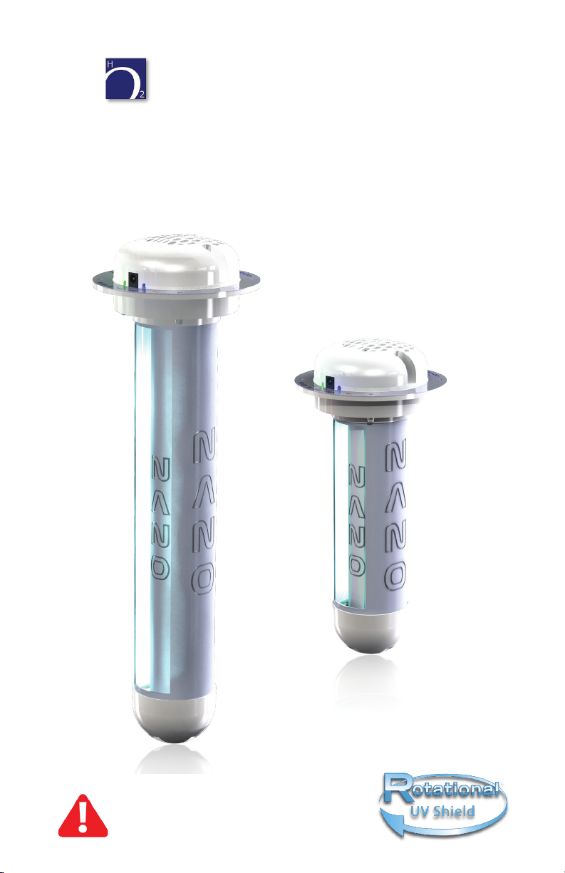
WARNING: UV LIGHT HAZARD.
Harmful to skin and eyes. Can cause
temporary or permanent loss of vision.
Never look at the lamp while illuminated.
To prevent exposure to ultraviolet light,
be sure the power is disconnected until
installation is completed and before ser-
vicing.
UV lamps contain Hg (Mercury).
High or long term exposure to Hg can lead to serious health risks. UV lamps should
be disposed of according to disposal laws in your area. UV lamps should never
be disposed via standard waste receptacles. They often break when thrown into a
dumpster, trash can or compactor, or when they end up in a landll or incinerator.
Learn more about proper disposal methods and nd disposal centers at www.
earth911.org.
Never touch UV lamp with bare hands. Oils from your skin can create hot
spots causing UV lamp to break when illuminated.
Never remove the outer housing of any components.
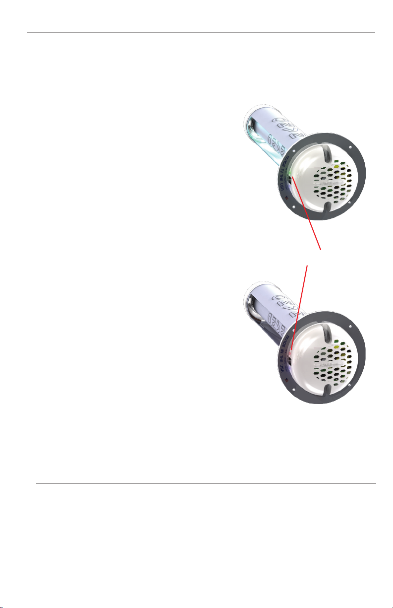
Cooling Vents
WARNING
OPTICAL RADIATION EXPOSURE HAZARD
DO NOT ATTEMPT TO OPERATE UNIT WITHOUT
PROPERLY INSTALLING UNIT FIRST.
PERMANENT EYE AND SKIN DAMAGE MAY RESULT.
1

Features and Benets
Easy Operation
The Central Air Purier is designed to operate continuously and should remain in
operation 24 hours a day, 7 days a week for best results.
Easy Installation
The Central Air Purier comes complete with installation hardware and takes just
minutes to install.
Low Maintenance
There is virtually no maintenance to perform. Our proprietary LongLife Quad-Ion
Cell, complete with the UVC lamp installed, should be replaced every two years.
Energy Efcient Green Technology
The Central Air Purier is an energy efcient air purication system. Other PCO
devices require several hundred watts to operate. The CAP3000 operates on just
13 watts of electricity and the CAP5000 operates on just 18 watts.
NANO Nickel Catalyst
Every unit utilizes our proprietary catalyst. Our catalyst utilizes TiO2and four ad-
ditional proprietary catalyst metals to provide remarkable results. This technology
reduces many biological and organic contaminants including mold, bacteria, virus-
es and VOCs.
Proprietary UVC Lamps
At the core of the Quad-Ion Cell is a UVC lamp. The 254 nm germicidal lamp kills
mold, bacteria, viruses and breaks down VOCs. They are American made lamps
that utilize a proprietary LongLife coating doubling the average life to two years.
A standard quartz lamp maintains 65% of its UVC output at 9,000 hours. With
LongLife technology, our UVC lamps maintain up to 80% of their output at 16,000
hours . Our lamps also utilize two-tube linear technology that protects against
breakage and mercury leakage, abrupt temperature changes, and high moisture
without decreasing efciency.
Rotational UV Shield Technology
The Quad-Ion Cell incorporates a proprietary UV shield technology. This technolo-
gy places you in control of how much or how little UV light is emitted from the unit.
You will learn more about this technology later in the manual.
Made in USA Quality
The CAP System is made in America with quality American engineered parts.
From durable light weight titanium anodized aluminum, down to the UV stabilized
polycarbonate housing, every part of the CAP System Induct is made with pristine
quality and assembled by hand in the USA.
2

Indications For Use
Technology
By utilizing a broad spectrum 254nm UV light we achieve the same oxidizing and
ionizing benets found in nature, created by the sun. Combining the UV light with
our catalyst we achieve remarkable results.
Internal walls of Quad-Ion Cell are
coated with PCO TiO2catalyst.
Long Life Germicidal UVC Lamps
Induct
Quad-
Ion Cell
CAP System devices are intended for the removal of air-
borne contaminations of pathogens and/or harmful molds
and volatile organic compounds present in rooms or en-
closed areas.
The device utilizes a PCO reaction chamber comprised of
an Quad-Ion Cell coated internally with a TiO2based cata-
lyst that reacts with photons from the 254nm UVC germi-
cidal lamp for the removal of airborne contaminations of
pathogens and/or harmful molds and volatile organic com-
pounds present in rooms or enclosed areas.
3

Status Indicator Lights
Power Adapter
The Status Indicator Lights are located on the side of the Ballast Cover. The indi-
cator lights will provide you with important information about the operating status
of your unit. The ballast and UVC lamp utilize this set of indicator lights to give
you detailed status information and ensure components are working properly. The
indicator lights will provide you with the following information:
“Lamp Status” Indicator
Green
Unit has power, ballast and UVC lamp are operat-
ing efciently.
Red
Unit has power, UVC lamp is defective or not prop-
erly connected. Unplug the device. Make sure
UVC lamp is properly connected. Plug unit back
into power source. If the light is still red please
contact an Air Fantastic representative.
“Lamp Replacement” Indicator
Blue Solid
The UVC lamp is within its two year life span. No
action is needed.
Blue Flashing
The UVC lamp is outside its two year life span,
has begun to decrease in efciency and should be
replaced.
No Lights Illuminated
There are two possibilities.
1. The unit is not properly connected to the pow-
er supply.
2. The ballast exceeded the safe operating temperature. The thermal protector
opened the circuit disconnecting power to the ballast. The circuit will automat-
ically reset when the ballast cools.
Status Indicator Lights
The CAP System is powered using a 24 VDC power adapter with a rated input
voltage of 100 - 240 VAC, Out 24 VDC and 1.5 A and 6 foot supply cord. For your
safety and to ensure proper function of your CAP System we recommend that
ONLY the power adapter included with the original purchase be used.
4

Ballast Assembly
Retainer Ring
Rotational UV Shield
Placement and Installation
The CAP System components are protect-
ed with a sturdy American made polycar-
bonate outer housing. This housing should
never be removed unless by an Authorized
Air Fantastic Representative.
Ballast Assembly
Retainer Ring
The Cap System Ballast Assembly and
Quad-Ion Cell are mounted to the Re-
tainer Ring. The Retainer Ring mounts
to the duct of your HVAC system and
utilizes an adhesive foam gasket to
prevent unwanted air leaks.
Since UV lamps were rst used in
HVAC systems there has been one
constant complaint from engineers
and contractors. UV light can degrade
many of the components used within
an HVAC system causing premature
system failure.
Air Fantastic has designed the perfect
solution. With the development of our
proprietary Rotational UV Shield you
can control how little or how much
UV light is emitted from the unit, while
allowing for a constant stream of air
to pass through the Quad-Ion Cell for
treatment.
The Rotational UV Shield can be ro-
tated 360˚ exposing more or less of
the UVC lamp.
Placement Suggestions
The CAP System units are designed to be installed within the duct of an HVAC
system. They can be mounted in either the supply side or return side of your
HVAC system. It should be placed within 10 feet of an electrical outlet. To help
you determine the optimal placement of your new CAP System we have listed a
few examples on the following page. We recommend that you always work with
an authorized dealer and licensed HVAC engineer or contractor when determining
optimal placement.
15˚ 45˚ 90˚
5

CAP System Placement Recommendations
• Above coils - The CAP System unit should be mounted directly above the
coils with UV Shields rotated 90˚ to the open position. The unit should be ori-
entated so that the UV light shines directly on the coils (“air ow” label should
be pointing at the coils). Larger air handlers may require multiple units.
• Reduce contaminants in duct- In residential or light commercial applications
a single unit can be mounted in the plenum on the supply side of the HVAC
system. In large commercial applications air can become recontaminated as
it travels through the ducts. Therefore it may be necessary to mount several
units throughout the duct. The UV Shield can be rotated to the closed position
when installing the unit in close proximity to seals and gaskets or electrical
components to protect them from the UV rays. When Rotational UV Shields
are in the closed position the CAP System should be installed with the “air
ow” label running parallel with the duct ensuring air ow through the device.
• When possible, the UV Shield should be rotated the open position for optimal
efciency to expose more contaminants to UVC radiation.
• Reduce airborne contaminants in a room - The CAP System unit should
be installed in close proximity to the air outlet vent that supplies air to the
room being treated. The UV Shield should be rotated to the closed position to
prevent human exposure to UV rays. When Rotational UV Shields are in the
closed position the CAP System should be installed with the “air ow” label
running parallel with the duct ensuring air ow through the device.
• Coverage - As a general recommendation the CAP3000 should be used in
areas up to 3000 square feet and the CAP5000 should be used for areas
between 3000 and 5000 square feet. Areas of higher contamination, areas
above 5000 square feet or with ceilings above 10 feet may require additional
units for best results.
CAP System
The duct work is trans-
formed into one big Puify-
ing Chamber when the
CAP System is installed.
Blower forces air through
ducting (reaction chamber)
Contaminated air
Purified air
Purified air
6

Preparing to Install Your New CAP System
The CAP System was designed to be simple and effective. Remove the unit,
power adapter, power cord, mounting hardware (eight self tapping screws) from
the box. We recommend keeping the box and all packaging material for shipping
the unit should it ever need to be returned for repairs.
Installation Instructions
Installation and servicing of air-conditioning equipment can be hazardous due to
system pressure and electrical components. Only trained and qualied service
personnel should install, repair, or service air-conditioning equipment. Air Fan-
tastic and its afliates are not responsible for any damage to the HVAC system,
CAP System or injury to yourself or others if you elect to install the device without
utilizing qualied technicians.
Use the suggestions on page 6 to determine the optimal mounting location(s).
To complete the installation process you will need the following tools:
• Power Drill
• 4 inch hole saw
• 1/4 inch hex head screw driver
1. Using the steps on page 6, determine the optimal mounting location of your
new CAP System. The mounting location should be within 10 feet of an elec-
trical outlet.
2. Thoroughly clean and dry at least a 12” X 12” area at the location where
the CAP System will be mounted. If available, clean with rubbing alcohol &
paper towel for a better adhesive seal to the duct. Be sure rubbing alcohol
dries completely. Using a 4” inch hole saw, cut a 4” hole in the duct where the
device will be mounted. Center the hole ensuring there will be at least a 5”
diameter of duct around the outside of the hole.
4”
5”
7

3. A trained service professional should be
consulted to determine the extent of rota-
tion. Rotate the UV Shield to the desired
opened or closed position. Place one
hand on the Distal Cap and the other on
the Outer UV Shield. Rotate the Distal
Cap clockwise while rotating the Shield
counter clockwise until the desired posi-
tion is reached. Rotation will require rm
pressure.
Note: The CAP unit is designed to re-
quire rm pressure during rotation. Never
rotate the Ballast Cover and Distal Cap
simultaneously in opposite directions.
Doing so could possibly disassemble the
unit and void the warranty.
Outer UV Shield
Distal Cap
Ballast Cover
4. Note that the CAP System should be orientated with the “air ow” label run-
ning parallel with the length of the duct to ensure the four pins are in line with
the Four Pin Connector. Before inserting the CAP System, use a 1/4” hex
head screw driver to remove the four outer screws and pull off the Ballast
Assembly from the Retainer Ring. Remove the wax paper from the gasket
located on the bottom side of the Retainer Ring. Insert the Retainer Ring with
the Quad-Ion Lamp attached into the 4” hole, aligning the cross hairs parallel
to the duct. Press rmly on the Retainer Ring to adhere the gasket to the duct.
5. Place Aluminum Tape Ring over Retainer Ring aligning the center. Firmly
press the Ballast Assembly onto the four pins protruding from the Quad-Ion
Cell Optional mounting congurations, such as opening the UV shields, may
vary the orientation of the “air ow” label. It’s only intended to serve as a gen-
eral guideline.
Duct
Retainer Ring
Cross Hairs
Cross Hairs
Quad-Ion Cell
Pin Orientation
8
Air Flow Label
Ballast Assembly
Be sure to insert the
Quad-Ion lamp with the
opening facing the air
ow.

6. Using a 1/4” hex head screw driver, secure the Ballast Assembly to the Re-
tainer Ring with four self tapping 3/4” screws being careful not to overtighten
stripping the screw holes. When mounting to a ber glass duct the adhesive
gasket will help secure the unit, but the four hex screws are still required to
secure the Ballast Assembly.
7. Using a 1/4” hex head screw driver, secure the power adapter with four self
tapping 1/2” screws.
8. Adhere the two included warning labels in close proximity to the CAP device.
Make sure the duct is clean and dry before adhering the warning labels.
9
Air Flow Label
Ballast Assembly
Aluminum Tape Ring
Retainer Ring

Plug the included power adapter into the CAP System. Connect the power adapter
provided with this unit rated input 100-240 Vac Output 24 Vdc and 1.5 A to electri-
cal outlet. The unit will start, with the green lights and blue lights illuminating.
It’s designed for continuous operation. For maximum effectiveness, operate the
unit 24 hours a day, 7 days a week.
Initial Start Up
10
Maintenance
The CAP System was engineered to be virtually maintenance free. The Quad-Ion
Cell should be replaced every two years.
Quad-Ion Cell Replacement Process
The Quad-Ion Cell comes complete with a new UVC lamp pre installed. The en-
tire Cell should be replaced every two years. Failure to replace the entire Cell
will decrease the effectiveness of the unit. After two years of use the blue Lamp
Replacement light will begin to blink as a reminder that it’s time to replace the
Quad-Ion Cell. The CAP System utilizes a proprietary UVC lamp that can only
be purchased from an authorized Air Fantastic dealer. The American made lamp
utilizes a proprietary long life coating increasing the average life to two years.
Our proprietary lamp also utilizes two-tube linear technology that protects against
breakage, abrupt temperature changes, and high moisture. Attempting to use an
alternative lamp will decrease the effectiveness of the unit, could cause permanent
damage to the unit and will void the warranty.
Note: UV lamps contain Hg (Mercury) and should be disposed of according to
disposal laws. Find disposal centers at www.earth911.org.
We recommend contacting an authorized Air Fantastic dealer to perform the
replacement process. If you choose to perform the replacement process yourself
please follow these directions:
1. Unplug the CAP device from its power source.

Maintenance (Continued)
2. Using a 1/4” hex head screw driver, remove the four screws securing the Bal-
last Assembly and pull the Ballast Assembly away from the Retainer Ring until
the four pins have completely disconnected from the Ballast Assembly.
3. Using a 1/4” hex head screw driver, remove the four screws securing the
Quad-Ion Cell and pull the Quad-Ion Cell out from the Retainer Ring. Properly
dispose of the Quad-Ion Cell. The four screws will be needed in step 4.
11
Be sure to insert the
Quad-Ion lamp with the
opening facing the air
ow.

4. Insert the new Quad-Ion Cell into
the Retainer Ring. Using the illus-
tration, be certain the Quad-Ion Cell
is installed using the correct pin ori-
entation. Secure the Quad-Ion Cell
with four 1/4” hex head screws.
Do not overtighten the screws
to prevent them from stripping.
5. Using a small cylindrical object, such as a pen,
press and hold the Lamp Reset Button for 3
seconds. This will reset the Lamp Replace-
ment Indicator. The Lamp Reset Button is lo-
cated on the bottom of the Ballast Assembly.
6. Firmly press the Ballast Assembly onto the four pins protruding from the
Quad-Ion Cell The Ballast Assembly should be orientated with the “air
ow” label running parallel with the length of the duct to ensure the four
pins are in line with the Four Pin Connector. Optional mounting cong-
urations, such as opening the UV shields, may vary the orientation of
the “air ow” label. It’s only intended to serve as a general guideline.
7. Using a 1/4” hex head screw driver, secure the CAP system with four self
tapping 3/4” screws being careful not to overtighten stripping the screw holes.
Outer Housing Maintenance
Never use harsh cleaners, chemicals or
abrasives on the plastic polycarbonate
housing or anodized aluminum. Only a
dry micro ber towel or a towel lightly
moistened with water should be used to
remove any dust or other debris from the
outside of the unit.
Lamp Reset Switch
12

CAP System Limited Warranty
Air Fantastic gives you the following limited warranty for this product only if it was
originally purchased directly from Air Fantastic or an Air Fantastic authorized dealer.
Air Fantastic will repair or replace, free of charge to the original purchaser, any part
that is found to be defective in material or workmanship within two (2) years of the
date of purchase.
This limited warranty does not apply to any part subjected to accident, abuse, al-
teration, misuse, lack of reasonable care, the afxing of any attachment not provid-
ed with the product, loss of parts, damage caused by acts of God, the use of volt-
ages other than indicated on the label displayed on this product or service of this
product by anyone other than Air Fantastic or an Air Fantastic authorized dealer.
Air Fantastic does not authorize any person or dealer to assume or grant any other
warranty obligation with the sale of this product.
To obtain service, the customer must rst register this unit by returning the en-
closed Warranty Card. If you purchase this product from any source other than
Air Fantastic or an Air Fantastic dealer, your purchase is “AS IS”, which means
Air Fantastic grants you no warranty, and that you, not Air Fantastic, assume the
entire risk of the quality and performance of this product, including the entire cost
of any necessary servicing or repairs of any defects.
Air Fantastic’ liability for damages to you for any costs whatsoever arising out
of this statement of limited warranty shall be limited to the amount paid for this
product at the time of original purchase, and Air Fantastic shall not be liable for
any direct, indirect, consequential or incidental damages arising out of the use or
inability to use this product.
ALL EXPRESS AND IMPLIED WARRANTIES FOR THIS PRODUCT, INCLUDING
IMPLIED WARRANTIES OF MERCHANTABILITY AND FITNESS FOR A PARTIC-
ULAR PURPOSE, ARE LIMITED IN DURATION TO THE WARRANTY PERIOD,
AND NO WARRANTIES, WHETHER EXPRESS OR IMPLIED, WILL APPLY AF-
TER THIS PERIOD.
Some states do not allow limitations on the duration of implied warranties, so the
above limitation may not apply to you. This warranty gives you specic legal rights,
and you may also have other rights which vary from state to state.
To obtain service and RMA number, contact an Air Fantastic representative at:
1-877-424-7326
NOTE: An RMA# is required for any warranty service work. All returned
packages that do not have an RMA# will be refused.
13

Troubleshooting Guide
CAP System Specications
Problem/Question Solution/Answer
What if my CAP won’t turn
on? The indicator lights
are not illuminated.
Check to make sure the power adapter is rmly
plugged into the electrical outlet and the CAP.
The Lamp Status indica-
tor light has turned from
green to red.
Reset the unit by unplugging it for the power source.
Check to make sure the four pins on the Quad-Ion
Cell are fully inserted into the Ballast Assembly. Re-
connect the power. If the indicator light is still red
contact Air Fantastic or an authorized dealer.
The Lamp Replacement
indicator light is blinking.
This is an indication that it has been two years since
the Quad-Ion Cell has been replaced. Contact an
Air Fantastic authorized dealer to purchase a new
Quad-Ion Cell.
If the above does not repair the symptom please contact an Air Fantastic Cus-
tomer Service Representative:
Phone: 1-877-424-7326
E-mail: [email protected]
Web: www.airfantastic.com
Mail: Air Fantastic
Customer Service
4406 Eagles Landing Dr.
Austin, TX 78735
Operational CAP3000 Coverage
CAP5000 Coverage
Ozone
Warranty
Up to 3000 Sq. Ft.
Up to 5000 Sq. Ft.
< .05 ppm
Two year limited warranty
Replacements AFION9N, AFION14N Replace every two years.
Electrical CAP3000 Usage
CAP5000 Usage
24 VDC, 0.50 Amps, 13 Watts
24 VDC, 0.68 Amps, 18 Watts
Mechanical CAP3000 Dimensions
Weight of Unit
Shipping Weight
CAP5000 Dimensions
Weight of Unit
Shipping Weight
4” L x 4” W x 10.7” H
1 lbs
4 lbs
4” L x 4” W x 15.8” H
1.4 lbs
4 lbs
Copyright © 2015 Air Fantastic
LLC
This manual suits for next models
1
Table of contents
Other Air Fantastic Air Cleaner manuals
Popular Air Cleaner manuals by other brands

KLOP INNOVATIONS
KLOP INNOVATIONS AIRCLEANER Pillar user manual

Colzer
Colzer KJ800 user manual

Philips
Philips MicroCube AC5659 user manual

asecos
asecos PURIFIAIR.620 operating manual

HENGST FILTRATION
HENGST FILTRATION Blue.care+ Original operating manual

Parkside
Parkside PDWE 8 A1 Operation and safety notes translation of the original instructions