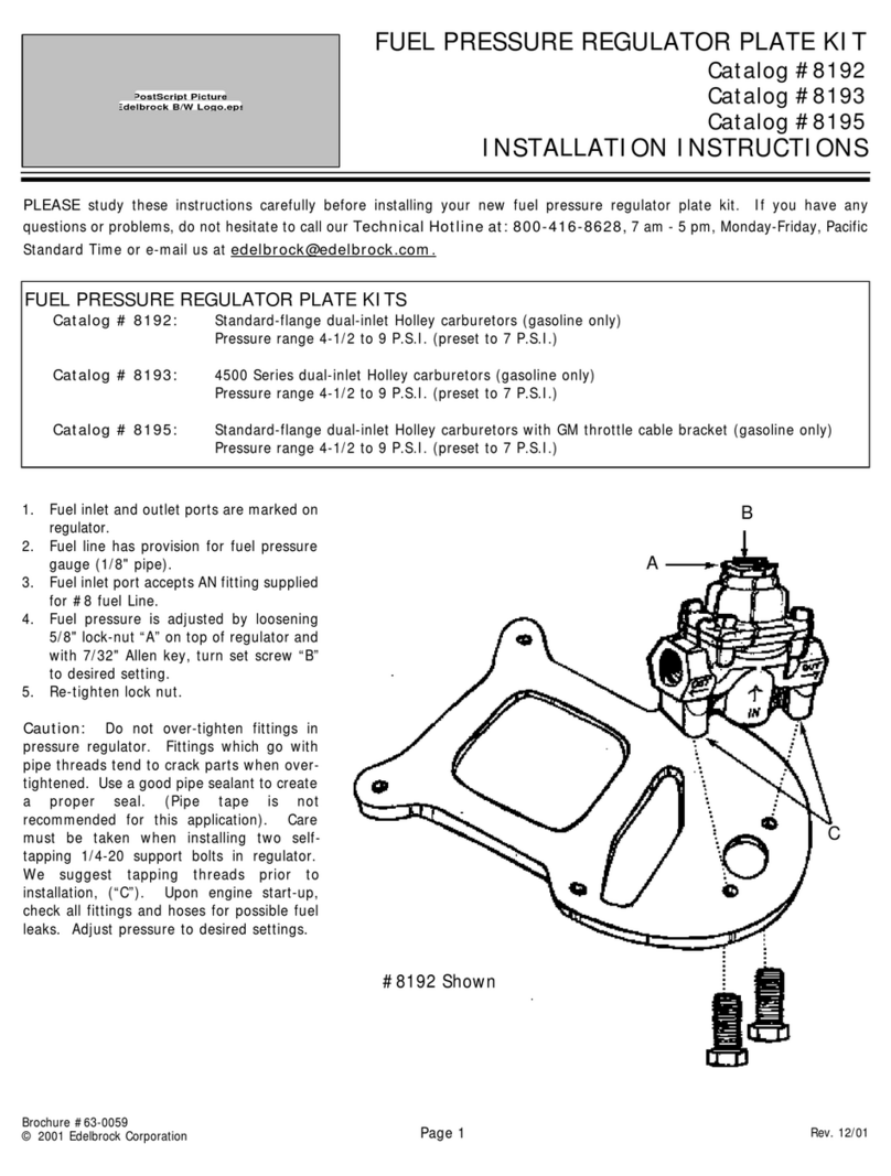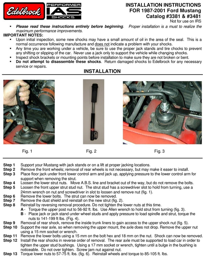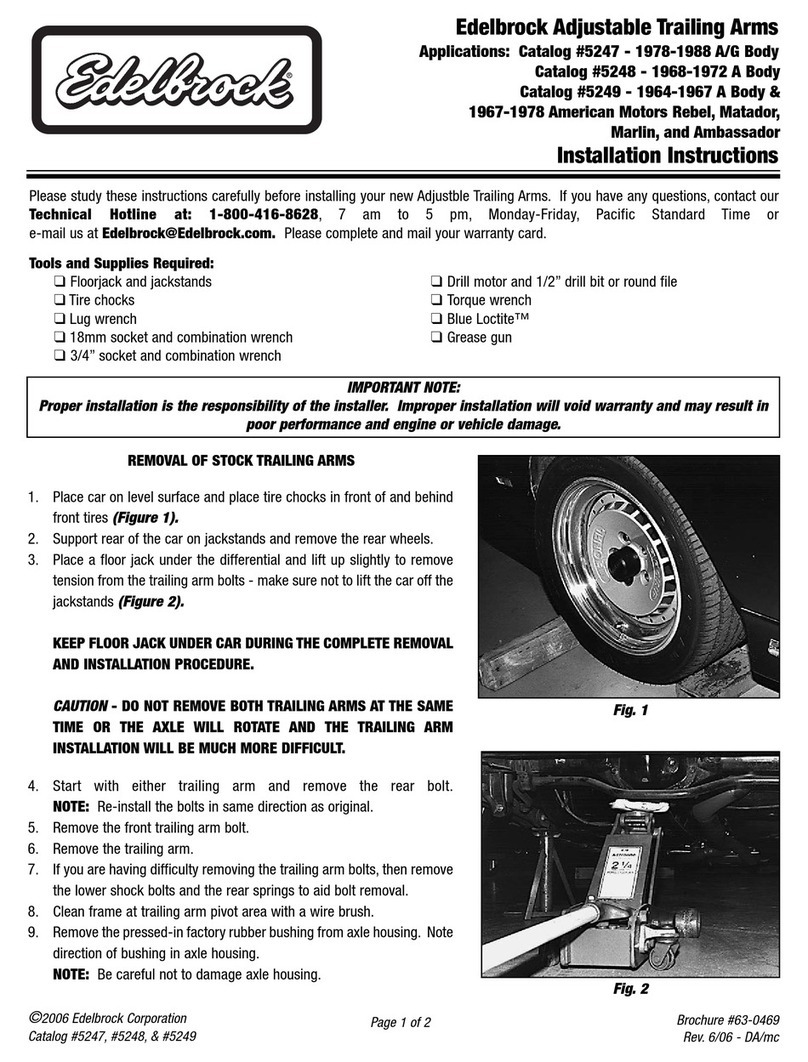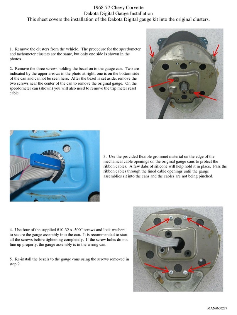
4MN-944
LoadLifter 5000 Ultimate
GETTING STARTED
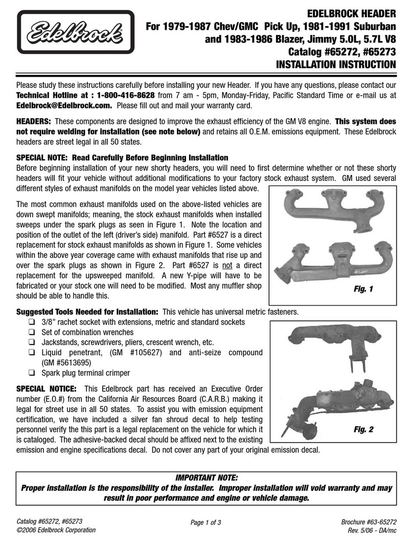
Inorder toinstall theupper framebrackets (A),it will be necessary toremove thecoil springs
as follows:
1. Lift the vehicle up and support the frame with jack stands. Leave enough room to drop
the axle down low enough to remove the coil springs (g. 2). Remove the rear wheels.
Installing the LoadLifter 5000 Ultimate System
TOOLS LIST
Description..............................................Qty
Hoist or oor jacks................................................1
Safety stands........................................................2
Safety glasses......................................................1
4” grinder or metal cutting tool.............................. 1
Torque wrench......................................................1
Standard open-end combo wrenches...................1
Ratchet.................................................................1
Metric and standard sockets.................................1
Description..............................................Qty
7/32 allen wrench (socket if available)..................1
1/4” and 5/16” drill bits (very sharp)...................... 1
Heavy duty drill.....................................................1
Hose cutter, razor blade, or sharp knife ............... 1
Air compressor or compressed air source............ 1
Spray bottle with dish soap/water solution ........... 1
Black paint or undercoating.................................. 1
Item Part # Description................................Qty
A 07061 Frame bracket.....................................2
B 07150 Air spring bracket................................2
C1 03017 L.H. lower bracket...............................1
C2 03112 R.H. lower bracket ..............................1
D 58496 Air sring...............................................2
E 11967 Roll plate.............................................4
F 21827 90° swivel tting ..................................2
G 17215 3/8”-24 x 2/4” at head screw .............4
H 17203 3/8”-24 x 2/4” hex head bolt................4
I 18427 3/8” lock washer..................................4
J 18444 3/8” at washer ...................................4
K 17102 5/16”-18 x 3/4” self-tapping screw.......6
L 17361 3/8”-16 x 1.25” Carriage Bolt..............12
Item Part # Description................................Qty
M 17495 M8-1.25” x 20 socket head screw.......2
N 18422 3/8”-16 serrated lock nut....................12
O 18522 M8-1.25” nylon nut..............................2
AA* 20086 Air line assembly.................................1
BB* 10466 Tie strap..............................................6
CC* 21230 Valve cap............................................2
DD* 18501 5/16” at washer .................................2
EE* 21234 Rubber washer....................................2
FF* 18401 Star washer.........................................2
GG* 21233 5/16” hex nut.......................................4
HH* 34365 Heat shield kit .....................................1
*Not shown in g. 1.
HARDWARE LIST
Missing or damaged parts? Call Air Lift customer
service at (800) 248-0892 for a replacement part.
STOP!
g. 2
