Air Monitor OAM II User guide

Precision Airflow Measurement
An ON
I
CON Brand
Precision Airflow Measurement
An ON
I
CON Brand
OAM II
Outdoor Airow Measuring System
Application Guide

OAM II APPLICATION GUIDE
Air Monitor Corporation 800.AIR.FLOW Page 2 onicon.com
0
500
1000
1500
2000
2500
3000
0.000 0.500 1.000 1.500 2.000 2.500
3.000
Velocity SFPM
Total Pressure Drop In wc
Required Fixed Inlet Total Pressure Drop Graph
1.00(25.40)
.90(22.86)
.80(20.32)
.70(17.78)
.60(15.24)
.50(12.70)
.10(2.54)
.09(2.29)
.08(2.03)
.07(1.78)
.06(1.52)
.40(10.16)
.30(7.62)
.20(5.08)
.05(1.27)
.04(1.02)
.03(.76)
.02(.51)
.01(.25)
100 (30)
200 (61)
300 (91)
400 (122)
500 (152)
600 (183)
700 (213)
800 (244)
900 (274)
1000 (305)
2000 (610)
3000 (914)
4000 (1219)
5000 (1524)
6000 (1829)
7000 (2134)
8000 (2438)
9000 (2743)
10,000 (3048)
INTAKE
EXHAUST
PRESSURE DROP
Air Velocity in feet and (meters) per minute through Free Area
Ratings do not include the effect of a bird screen
Static Pressure Drop in inches w.g. and (mm)
Example of a louver pressure drop graph
Blowing dust and debris, moist air and low ow velocities are just some of the
problems commonly associated with outdoor airow measurement. These
conditions can be very challenging when trying to accurately measure the
amount of outdoor air entering a building using thermal or Pitot style airow
elements. Air Monitor’s OAM II Outdoor Airow Measurement System is
specically designed to provide accurate airow measurement in this
challenging application.
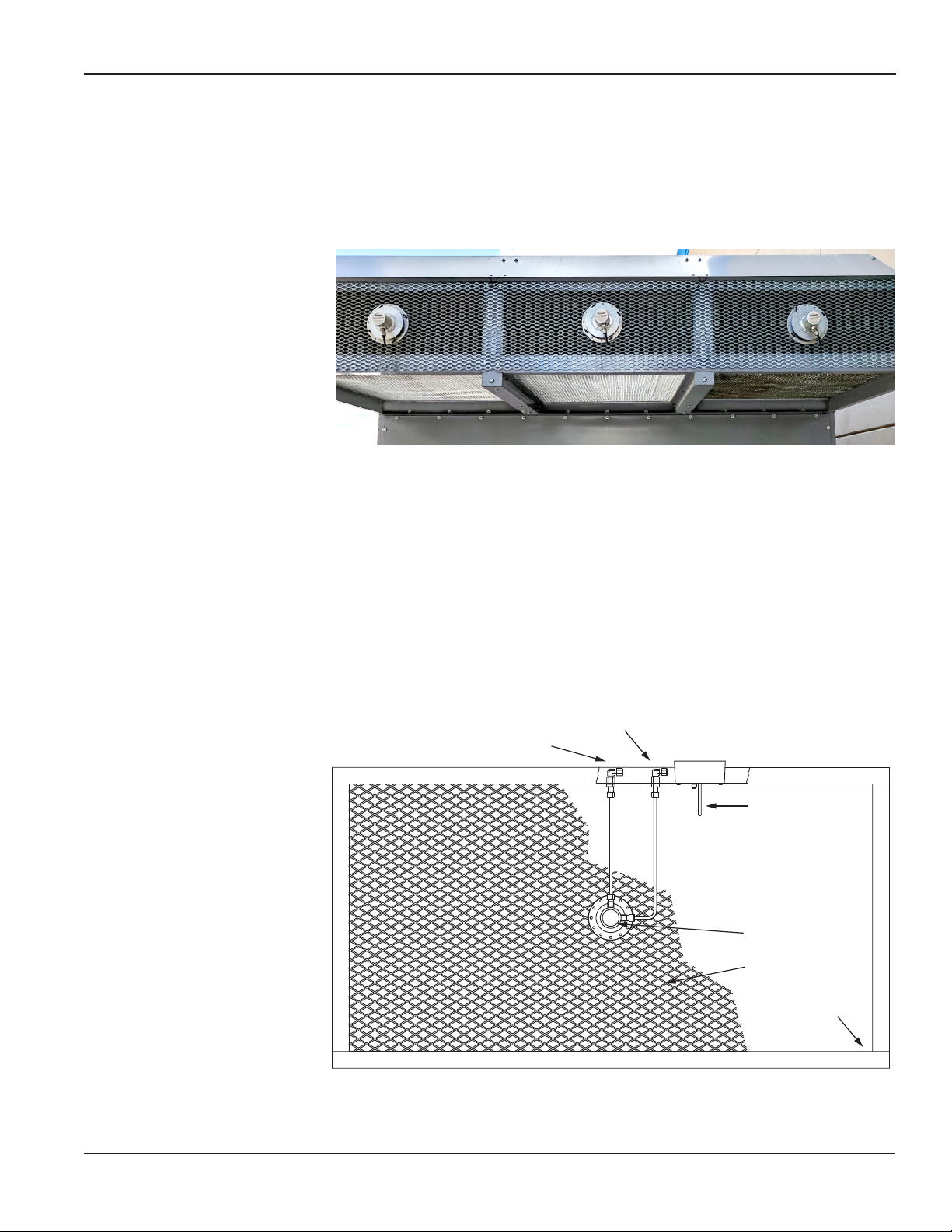
Each OAM II consists of a dedicated transmitter with a built-in barometric
pressure sensor, reference temperature sensor(s) and uni-sensor ow element(s).
The system oers exceptional performance in this dicult but extremely
important airow measurement application.
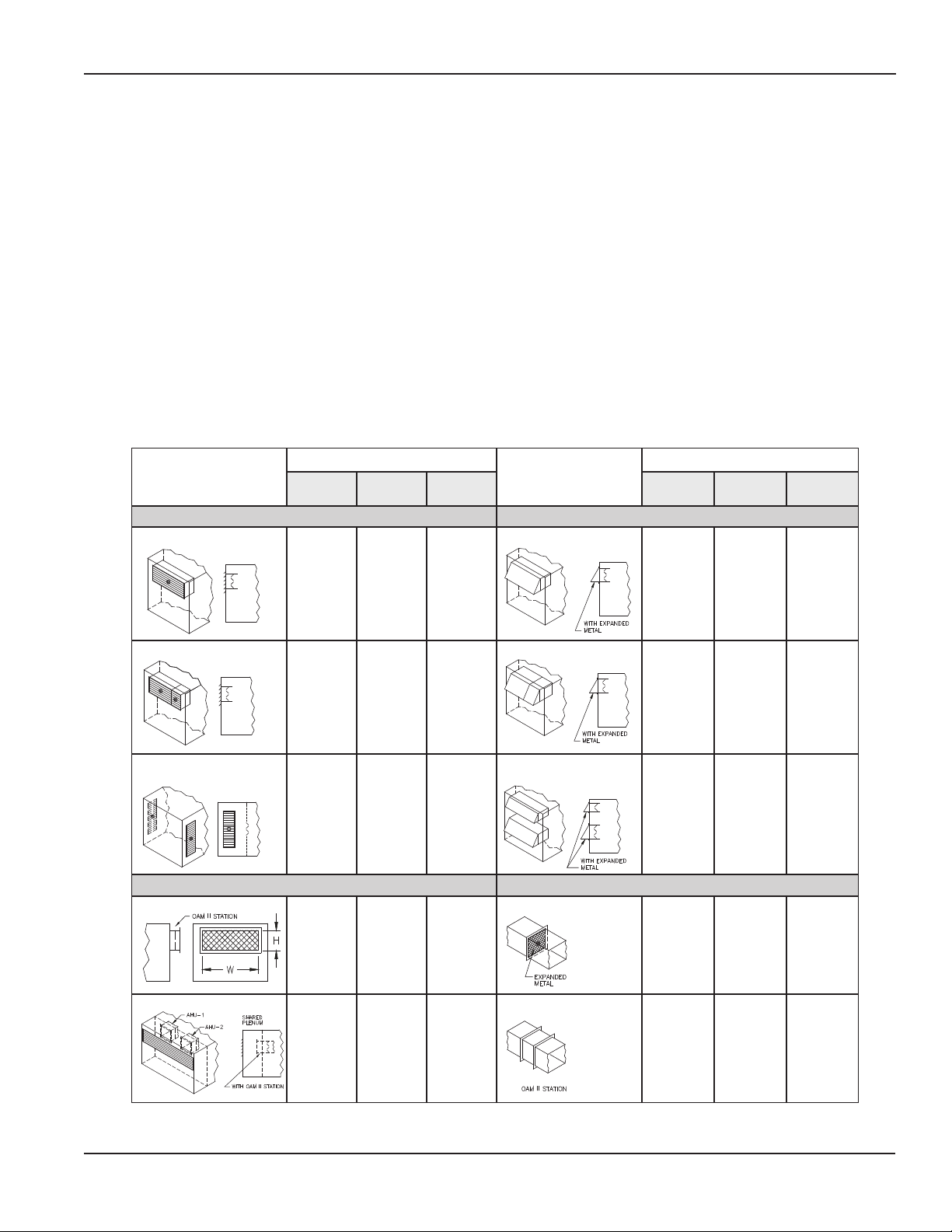
There are three dierent OAM II congurations. Each oers distinct advantages
for some of the most common outdoor airow applications. This guide
presents an overview of airow inlet types, OAM II congurations, and system
components. Consider the following when selecting an outdoor airow
measurement system.
What is the airow inlet type?
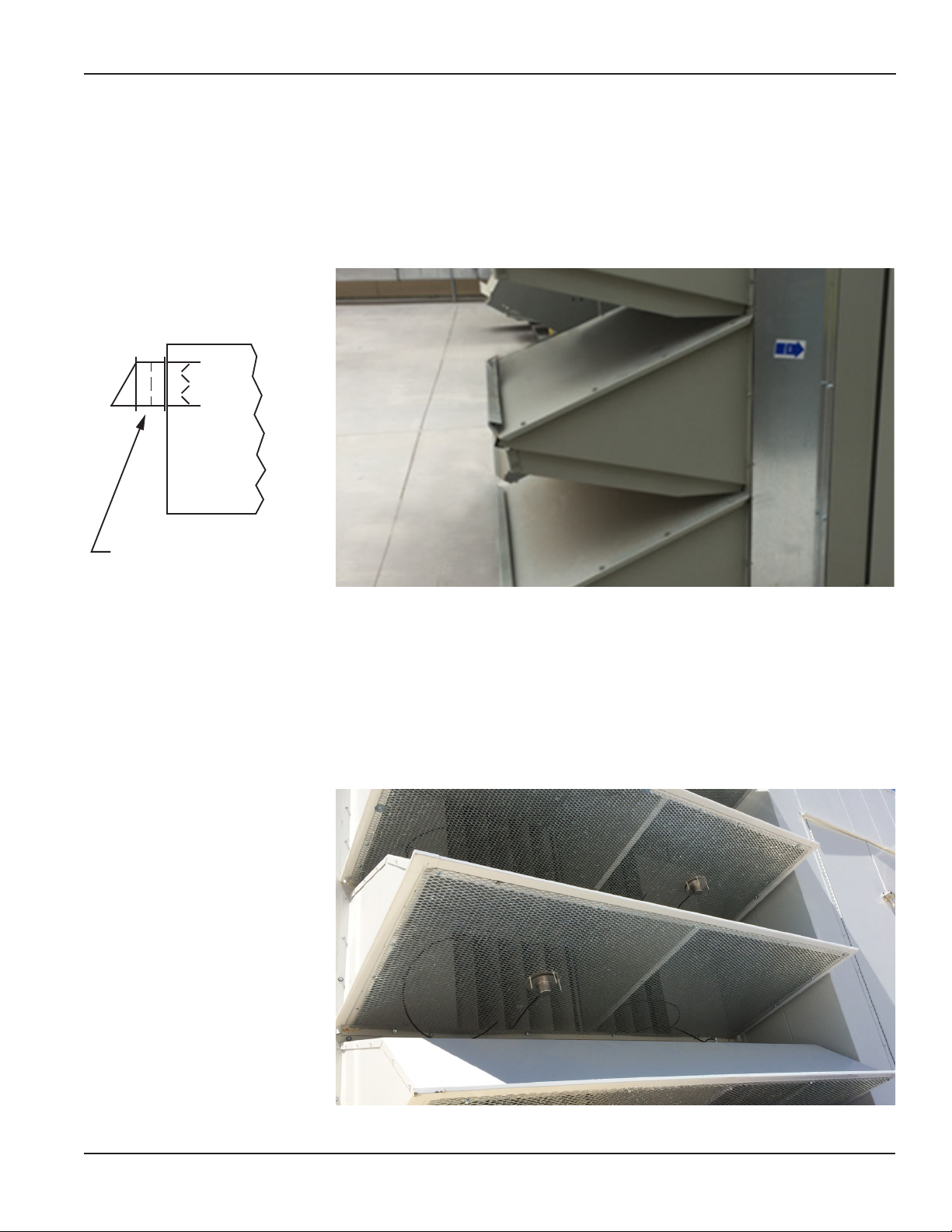
There are a variety of inlet types. The most common inlets incorporate
architectural louvers or packaged roof top units with single or multiple rain
hoods. The OAM II utilizes the static dierential pressure eld created by the air
entering and moving through the xed inlet. The dierential pressure required
to achieve accurate airow measurement is indicated in the graph below. Refer
to the louver manufacturer’s published pressure drop data to conrm it is
adequate to meet your application requirements.
What is the airow inlet size/geometry?
Many systems are large enough or shaped such that they will require multiple
uni-sensors connected in parallel to eectively average total airow through
the inlet. Minimum/Economizer (split) inlets may also require multiple sensors.
What is the best OAM II conguration for my applications?
The OAM II is available in three dierent factory congurations based on your
inlet type. Each conguration is optimized for a specic airow application. A
detailed description of each conguration is provided on the next page.
SECTION 1.0
INTRODUCTION

OAM II APPLICATION GUIDE
Air Monitor Corporation 800.AIR.FLOW Page 3 onicon.com
Inlet Types
System Congurations
Inlet Types
System Congurations
Single
System
Min/Econ
(Split)
Dual
System
Single
System
Min/Econ
(Split)
Dual
System
LOUVERED INLET RAIN HOOD INLET
SINGLE
√
SINGLE
√
SPLIT
√
SPLIT
√
MULTIPLE INLETS OF
EQUAL AREA
√
DUAL
√
FREE INLET DUCTED INLET
SINGLE
√
EXPANDED METAL
√
DUAL
√
STATION
√
SECTION 2.0
CONFIGURATIONS
The OAM II can be factory congured to operate in three dierent modes.
Single Channel, Single System Airow Measurement – This conguration
provides airow measurement from 150 to 2400 FPM. It is ideal for measuring
highly variable airow in a single inlet.
Minimum/Economizer (Split) Airow Measurement – The Min/Econ
conguration provides combined airow measurement for separate minimum and
economizer inlets. The OAM II is an eective tool for measuring this commonly
used inlet conguration.
Dual Channel, Dual System Airow Measurement – The dual channel
conguration provides two separate airow measurements in one transmitter. Ideal
for built-up systems that provide outdoor air to multiple locations.

OAM II APPLICATION GUIDE
Air Monitor Corporation 800.AIR.FLOW Page 4 onicon.com
OUTDOOR AIR
CONTROL DAMPER
AIR
FLOW
VOLU-o/OAM II
UNI-SENSOR
LOUVERED INLET
BIRD SCREEN
Install the uni-sensor as close to the center of the inlet as possible. The distance
between the tip of the uni-sensor and the edge of the fully open damper blade
should be at least 2”. See drawing below.
Louvered Inlets:
Install the uni-sensor on the front face of the louver. The louver size and
shape will determine the number of sensors required for the inlet. If the louver
manufacturer, model number, net free area and free area velocity vs. pressure
drop information is provided, Air Monitor will factory characterize the OAM II
transmitter. This will eliminate the need for eld characterization.
The louver depth will dictate the length of the uni-sensor probe (louver depth
+ 2”). Standard probe lengths are available in 1” increments.
SECTION 3.0
INLET TYPES

OAM II APPLICATION GUIDE
Air Monitor Corporation 800.AIR.FLOW Page 5 onicon.com
OAM II STATION
Rain Hood Inlets:
The inlet must produce the required pressure drop (as shown in the graph on
page 2) in order to accurately measure the airow through the inlet. The use of
expanded metal across the inlet or an airow station provided by Air Monitor
will greatly simplify the installation process and eliminate the need for eld
characterization. If an OAM II Airow Station is used, it can be sandwiched
between the rain hood and the AHU’s OA damper.
Minimum/Economizer (Split) Inlets:
In the installation below, two inlets separately provide minimum and
economizer outside airows to a single air handler. The OAM II, operating in a
dual channel, single system conguration would provide both individual and
totalized airow rate information.

OAM II APPLICATION GUIDE
Air Monitor Corporation 800.AIR.FLOW Page 6 onicon.com
OAM II STATION
AIR
FLOW
Ducted Inlets:
OAM II Stations or expanded metal screens installed in ducts should be located
such that there is no interference upstream or downstream that would intrude
into the OAM II station casing or into the area where the uni-sensor is installed.
WITH OAM II STATION
PLENUM
PLENUM INLET
WITH OAM II STATION
PLENUM
PLENUM INLET
UNI-SENSOR
MOUNTED ON
EACH INLET
SIGNALS
MANIFOLDED
TOGETHER
Plenum Inlets:
When mounting an OAM II station directly to a damper casing, conrm
there is sucient clearance between the fully open damper blades and
the uni-sensor probe. If required, an extended case OAM II Station can be
provided in order to achieve the required 2” minimum distance.
Multiple Inlets:
Uni-sensors installed on each inlet are connected via manifolds or tees to
provide averaged sensor signals to the transmitter. The area of each inlet
should be identical for best results, and inlet dampers must operate in unison.
OAM II STATION

OAM II APPLICATION GUIDE
Air Monitor Corporation 800.AIR.FLOW Page 7 onicon.com
OAM II Station (shown with a single uni-sensor)
OUTSIDEAIR MONITOR
VOLU-flo/OAM ll
UNI-SENSOR
FLANGE
EXPANDED METAL
TEMPERATURE
SENSOR
LOW PRESSURE PORT
HIGH PRESSURE PORT
Inlets with an Aspect Ratio >6:1 & Inlets with an Area >30 ft2:
Inlets with an aspect ratio >6:1 require the use of multiple uni-sensors spaced
at equidistant intervals. For example: A 2’ x 30’ louvered inlet has an aspect
ratio of 15:1. Use three equally spaced sensors serving 2’ x 10’ areas to reduce
the aspect ratio to 5:1 for each sensor. Another example; if a unit has a 7’ x 12’
inlet, three sensors are required with each covering a 7’ x 4’ area.
OAM II Stations are built to order and are delivered fully assembled. The number
of sensors provided varies based on the size and shape of the station. When
multiple OAM II stations are provided for a single system, only one station will
include an RTD temperature sensor.
OAM II Stations are built using attened galvanized or stainless steel expanded
metal with 63% open (free) area, 0.05” thickness, and 0.50” SWD x 1.25” LWD x
0.096” strand width. The ow and pressure drop characteristics of this expanded
metal is fully dened. This simplies the installation as the airow station is
provided fully characterized from the factory.
SECTION 4.0
AIRFLOW STATIONS

Precision Airflow Measurement
An ON
I
CON Brand
1050 Hopper Avenue • Santa Rosa, CA 95403 • USA
(P) 800.AIR.FLOW • www.airmonitor.com
DOC-0001939
OAM II APPLICATION GUIDE
February 2019
The uni-sensor is constructed of 316 stainless steel and is resistant to
corrosion caused by salt and most other airborne corrosives. It combines an
outside reference (high pressure) sensor and an inlet airow (low pressure)
sensor into one assembly. They are provided with probe lengths that match
the clearance requirements of the inlet where they will be installed.
Uni-sensors are ideal for retrot installations because they are easily
mounted to a variety of existing inlet types.
IMPORTANT NOTE
Air Monitor’s OAM II system is provided with an easy-to-use eld
characterization program. Test and balance ow data is entered,
automatically adjusting the factory OAM II response curve. Field
characterization is recommended for those installations where the inlet
type is not fully dened at the factory.
SECTION 5.0
AIRFLOW SENSORS
Other manuals for OAM II
1
Table of contents
Other Air Monitor Measuring Instrument manuals

Air Monitor
Air Monitor OAM II User manual

Air Monitor
Air Monitor ELECTRA-flo / SD User manual

Air Monitor
Air Monitor AUTO-purge III User manual

Air Monitor
Air Monitor VOLU-flo/OAM II User guide

Air Monitor
Air Monitor ELECTRA-flo / SD User manual

Air Monitor
Air Monitor FAN-E Operating and maintenance manual
Popular Measuring Instrument manuals by other brands

NF
NF FRA5014 instruction manual

Milwaukee
Milwaukee MC310 user manual

Teledyne
Teledyne HASTINGS Everywhereyoulook 201 Series instruction manual

Keysight
Keysight N5221A Security Features and Document of Volatility

Keysight
Keysight x series Measurement guide

Reed Instruments
Reed Instruments R3000SD instruction manual