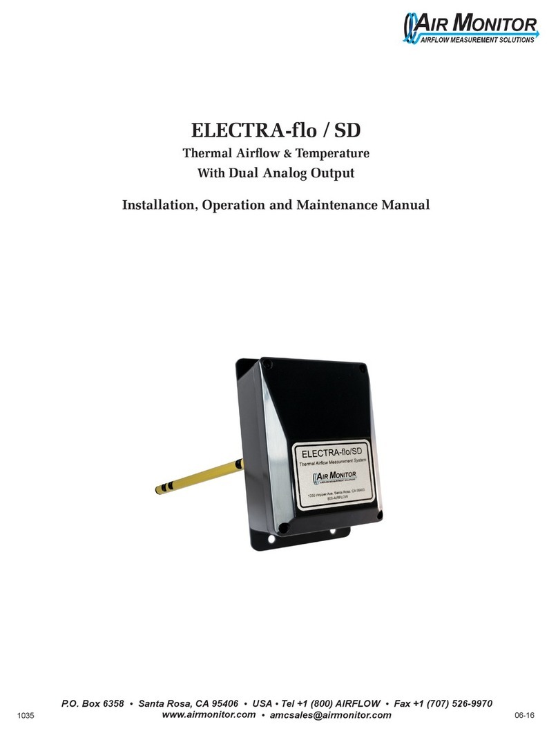
Air Monitor ELECTRA-flo / SD User manual

Precision Airflow Measurement
An ON
I
CON Brand
ELECTRA-o SD
Thermal Airow & Temperature
With BACnet MS/TP or MODBUS RTU Output

Air Monitor +1 (800) airow Page 2 www.airmonitor.com
ELECTRA-FLO SD
SAFETY
INFORMATION
This meter was calibrated at the factory before shipment. To ensure correct use of
the meter, please read this manual thoroughly.
Regarding this Manual:
• This manual should be passed on to the end user.
• Before use, read this manual thoroughly to comprehend its contents.
• The contents of this manual may be changed without prior notice.
• All rights reserved. No part of this manual may be reproduced in any form
without Air Monitor’s written permission.
• Air Monitor makes no warranty of any kind with regard to this material,
including, but not limited to, implied warranties of merchantability and
suitability for a particular purpose.
• All reasonable eort has been made to ensure the accuracy of the contents
of this manual. However, if any errors are found, please inform Air Monitor.
• Air Monitor assumes no responsibilities for this product except as stated in
the warranty.
• If the customer or any third party is harmed by the use of this product, Air
Monitor assumes no responsibility for any such harm owing to any defects
in the product which were not predictable, or for any indirect damages.
SAFETY PRECAUTIONS:
The following general safety precautions must be observed during all phases
of installation, operation, service, and repair of this product. Failure to comply
with these precautions or with specic WARNINGS given elsewhere in this
manual violates safety standards of design, manufacture, and intended use of
the product. Air Monitor Incorporated assumes no liability for the customer’s
failure to comply with these requirements. If this product is used in a manner
not specied in this manual, the protection provided by this product may be
impaired.
The following messages are used in this manual:
WARNING: Messages identied as “Warning” contain information regarding
the personal safety of individuals involved in the installation, operation or
service of this product.
CAUTION: Messages identied as “Caution” contain information regarding
potential damage to the product or other ancillary products.
IMPORTANT NOTE: Messages identied as “Important Note” contain
information critical to the proper operation of the product.

Air Monitor +1 (800) airow Page 3 www.airmonitor.com
ELECTRA-FLO SD
1.0 INTRODUCTION........................................................................................................................................
1.1 PURPOSE OF THIS GUIDE...............................................................................................................................................
1.2 TYPICAL METER INSTALLATION...................................................................................................................................
2.0 SPECIFICATIONS........................................................................................................................................
3.0 INSTALLATION...........................................................................................................................................
3.1 INSTALLATION ....................................................................................................................................................................
3.2 RECEIVING & INSPECTION.............................................................................................................................................
3.3 PLACEMENT GUIDELINES................................................................................................................................................
3.4 MOUNTING .........................................................................................................................................................................
3.5 POWER/SIGNAL CONNECTIONS..................................................................................................................................
3.6 CONFIGURATION ..............................................................................................................................................................
3.7 START-UP / OPERATION..................................................................................................................................................
3.8 LEDs ........................................................................................................................................................................................
4.0 BACnet MS/TP or MODBUS RTU...............................................................................................................
4.1 CHANGING THE MAC ADDRESS AND DEVICE INSTANCE NUMBER..............................................................
4.2 BACnet PIC STATEMENT...................................................................................................................................................
4.3 AVAILABLE BACnet OBJECTS..........................................................................................................................................
4.4 ADDITIONAL BACnet OBJECT INFORMATION........................................................................................................
4.4.1 Device Object................................................................................................................................................................
4.4.2 Analog Input Objects.................................................................................................................................................
4.4.3 Analog Value Objects................................................................................................................................................
4.5 MODBUS RTU MEMORY MAP.......................................................................................................................................
5.0 MAINTENANCE / INSPECTIONS..............................................................................................................
5.1 TROUBLESHOOTING.........................................................................................................................................................
4
4
4
5
6
6
6
6
7
8
9
10
10
11
11
14
15
15
15
16
16
17
18
18
TABLE OF CONTENTS

Air Monitor +1 (800) airow Page 4 www.airmonitor.com
ELECTRA-FLO SD
1.0 INTRODUCTION We, at Air Monitor, would like to thank you for purchasing our quality, U.S. made,
Thermal Airow & Temperature Measurement System. As our valued customer,
our commitment to you is to provide fast, reliable service and assistance, while
continuing to oer you new products to meet your growing ow measurement
needs.
We have written this guide to provide the persons responsible for the installation,
operation and maintenance of your thermal airow measurement system with the
most specic equipment information they will need. This is NOT an electrical or
HVAC trade manual. This guide is the basic reference tool for the ELECTRA-o/SD
with BACnet MS/TP or MODBUS RTU only.
Air Monitor’s ELECTRA-o/SD accurately measures the average velocity of
owing air by means of thermal dispersion at the surface-mount thermistor
sensor locations in the duct. Temperature is also measured via these thermistors.
Microprocessor based circuitry within the enclosure then converts the rate of
thermal dispersion into average airow velocity and temperature analog signals
which are transmitted via a BACnet® MS/TP or MODBUS® RTU with a customer-
installed cable to the local BMS.
1.1 PURPOSE OF THIS GUIDE
1.2 TYPICAL METER INSTALLATION
VAV Installations Option 1: Locate ELECTRA-flo/SD a
minimum of 3" upstream of the VAV box, or 3" upstream
of the pneumatic flow ring (remove the ring).
3" Upstream
Minimum
1 Duct Diameter
Minimum
VAV Box
Flow Direction
½" Conduit Outlet
Square Duct Round Duct
VAV Installations Option 2: When mounted downstream
of the VAV box, position the ELECTRA-flo/SD a minimum
or one duct diameter downstream of the VAV box.
Equivalent Duct Diameter X
Rectangular Duct: X = 2 (HxW) Circular Duct: X = Duct Diameter
H+W

Air Monitor +1 (800) airow Page 5 www.airmonitor.com
ELECTRA-FLO SD
ELECTRA-o/SD
ACCURACY Sensor Accuracy
Velocity: ±2% of reading from 0 – 3,000 FPM
Temperature: ±0.15ºF
Overall System Accuracy
Flow: ±3% of actual ow from 0 – 3,000 FPM
Temperature: ±0.15ºF of air temperature
RANGE Velocity Range: 0 to 3000 FPM
PROBE
ASSEMBLY
Mounting
Standard mounting bracket: 6063 aluminum with four ¼” holes for fasteners. ¼” thick neoprene gasket
Optional Type 316 stainless steel mounting plate
Length: 4”, 5”, 6”, 7”, 8”, 9”, 10”, 12”, 14”, and 16”
Sensors Per Probe
4” probe, one sensor
5”-16” probes, two sensors
Probe
Type: 6063 anodized aluminum. ½” diameter tubing
Optional: Type 316 stainless steel
Sensor Housing: Injection molded polycarbonate, UL94 V-0 rated
Sensor Type: Surface mount precision thermistor
TRANSMITTER Enclosure: NEMA 4 rated. Injection molded polycarbonate UL94 V-0 rated
Electrical Connections: Separate power and signal terminal strips with plug-in connectors
Outputs
BACnet MS/TP or MODBUS RTU
BAUD Rates: 76800, 38400, 19200 or 9600 available by DIP switch
Termination: 120 Ω termination available by DIP switch
Points List: BACnet / MODBUS
Name Object Type Units
Flow Velocity Ai / Holding register Feet per Minute, Meters per Minute
Flow Velocity Pressure Ai / Holding register Inches of Water, Millimeters of Water
Temperature Ai / Holding register Degrees Fahrenheit, Degrees Celsius
Volumetric Flow Ai / Holding register Cubic Feet per Minute, Cubic Meters per Minute
Duct Area Scale Factor AV / Holding register Square Feet, Square Meters
Conguration: Via two 8-position DIP switches
Filter: User selectable via DIP switch – none, light, medium, and heavy
Temperature Limits
–20ºF to 120ºF Transmitter
–20ºF to 120ºF Airow
Humidity Limits: 0 to 99% RH, non-condensing
POWER Power Supply: 24 VAC (20-28 VAC) or 24 VDC (20-40 VDC), automatically selected
Power Consumption: 5 VA or 5 W
Circuit Protection: Power input is isolated, fused, and reverse polarity protected
IMPORTANT NOTE: Specications subject to change without notice.
SECTION 2.0: SPECIFICATIONS

Air Monitor +1 (800) airow Page 6 www.airmonitor.com
ELECTRA-FLO SD
3.0 INSTALLATION
The ELECTRA-o/SD is intended for use in 4” to 16” ducts and in VAV terminal
box applications in an environment between -20°F to 120°F where it will not be
exposed to rain or snow. The ELECTRA-o/SD electronics enclosure is designed to
be mounted to the exterior of the duct or VAV box with the sensor probe inserted
through the side of the duct or VAV box.
Carefully remove the ELECTRA-o/SD from the shipping container and inspect for
any damage. If damaged, contact Air Monitor’s Service Department. Verify that
the shipping container includes the four self-tapping mounting screws in addition
to this manual.
Location of the ELECTRA-o/SD is critical for proper operation and accuracy
of the airow measurement. The typical installation diagrams below show the
minimum distance between a source of airow disturbance (elbow, transition,
duct take-o, etc.) and the meter.
• If more than the minimum clearances are available, proportionally adjust
the upstream and downstream distances.
• Avoid locating the ELECTRA-o/SD where it will be subjected to
condensing moisture from a coil.
• Contact Air Monitor’s Applications Engineering Department to discuss any
sub-minimal installation.
3.1 INSTALLATION
3.2 RECEIVING & INSPECTION
3.3 PLACEMENT GUIDELINES
VANED
ELBOW
.75X .5X
0.5X 0.5X 0.5X
1X
.75X1.5X
SWEEP
ELBOW
1X
0.75X
2X
BELLMOUTH INLETS
PLENUM
TAKEOFF
1.5X
DUCT
BRANCH
4X
Rectangular Duct: X = Circular Duct: X = Duct Diameter
Equivalent Duct Diameter X
H+W
2(HxW)
EXPANDING TRANSITION
≤
α
α
≤
ELBOW
UNVANED
REDUCING TRANSITION
2.5X 1X
DAMPERS
α
α
• VAV Installations - Locate the ELECTRA-o/SD a minimum of 3” upstream
of the VAV box or 3” upstream of a pneumatic ow ring (remove the ow
ring). When mounting downstream of the VAV box, position the ELECTRA-
o/SD a minimum of one duct diameter downstream of the box.

Air Monitor +1 (800) airow Page 7 www.airmonitor.com
ELECTRA-FLO SD
1. Determine the measurement location based upon the engineer’s plans and
the ELECTRA-o/SD’s minimum placement guidelines.
IMPORTANT NOTE: It may be necessary to remove a portion of external
duct insulation to allow the ELECTRA-o/SD to be securely mounted to the
exterior of the duct wall.
2. Remove the four screws (8-32 x 0.325) that attach the mounting bracket to
the enclosure. Place the mounting bracket against the duct wall where the
ELECTRA-o/SD is to be mounted and trace the large probe insertion hole
in the center of the bracket onto the duct. See Figure 2.
3. Using a 3/4” hole saw, cut the insertion hole.
4. Place the mounting bracket centered over the insertion hole. Align the
edge of the mounting bracket parallel with the axis of the duct, then
attach the mounting bracket to the duct using the provided sheet metal
screws ( 8-32 x 0.75”).
5. Place the probe through the mounting hole, center the gasket in the
hole in the bracket so it makes contact with the duct, then attach the
enclosure to the mounting bracket at the four mounting holes using the
four screws (8-32 x 0.325”) previously removed in Step 3 above.
3.4 MOUNTING
Figure 2

Air Monitor +1 (800) airow Page 8 www.airmonitor.com
ELECTRA-FLO SD
The ELECTRA-o/SD provides a eld selectable BACnet MS/TP or MODBUS
RTU output for airow velocity, equivalent velocity pressure, temperature, and
volumetric ow which is scaled based on the present value set to the BACnet
Analog Value 0 (MODBUS Holding Register 8) object.
Power wiring is done at terminal strip J1, and RS-485 signal wiring is done at
terminal strip J2. Both terminal strips are located in the lower corners of the
transmitter and are accessible by removing the enclosure cover. See Figure 3.
One ½” conduit opening is provided in the bottom of the enclosure for power
and signal wiring.
It is recommended that power wiring be 18 awg and signal wiring be 18
awg to 22 awg. 16 awg is the maximum wire gauge that the terminals can
accommodate. To aid the wiring process, terminals J1 and J2 are removable
by pulling the terminal strip straight up and o the circuit board. Once wiring
has been completed replace the terminals by aligning with the receptacle and
pressing rmly.
The ELECTRA-o/SD can be powered by either 24 VAC providing 20-28 VAC or
24 VDC providing 20-40 VDC.
CAUTION: To prevent damage to the ELECTRA-o/SD, the 24 VAC/VDC
power source must be turned o before making the power and signal
connections.
CAUTION: Incoming and outgoing RS485 cable shield wires should be
connected together, but must not be connected to the RS485 ground.
3.5 POWER/SIGNAL CONNECTIONS
Figure 3
RS-485 (+)(B)
RS-485 (-)(A)
RS-485 Ground/Common
J1
Run Mode and
Network Status LEDs
J2
24VAC neutral / 24VDC(-)
24VAC line / 24VDC(+)

Air Monitor +1 (800) airow Page 9 www.airmonitor.com
ELECTRA-FLO SD
All device conguration is done using two 8-switch DIP packages labeled S1
and S2 that can be accessed by removing the enclosure cover. The protective
shield over the circuit board also has a reference guide for setting all device
congurations. See Figure 4. Conguration settings can be changed while the
device is powered.
3.6 CONFIGURATION
None
Parity (Modbus only)
Modbus
BACnet*Odd
Even*
IMPORTANT NOTE: * denotes the default setting. All conguration settings
are shipped from the factory in the default mode.
Figure 4
S1 Bank, SW1 & SW2 Parity (MODBUS only)
Down Down None
Up Down Odd
Down Up Even*
S1 Bank, SW5 BACnet / MODBUS
Down BACnet*
Up MODBUS
S1 Bank, SW6 & SW7 Baud Rate
Up Up 9600
Up Down 19200
Down Up 38400
Down Down 76800*
S1 Bank, SW8 – RS-485 Termination
Up Engaged
Down Not Engaged (No Termination)*
S2 Bank, SW1 U.S. / SI Units
Up SI Units
Down US Units*
S2 Bank, SW2 through SW8 BACnet Addressing
7 Bit BACnet MS/TP MAC Address and Instance Number Conguration

Air Monitor +1 (800) airow Page 10 www.airmonitor.com
ELECTRA-FLO SD
SW8 Bit0 (Decimal 1)
SW7 Bit1 (Decimal 2)
SW6 Bit2 (Decimal 4)
SW5 Bit3 (Decimal 8)
SW4 Bit4 (Decimal 16)
SW3 Bit5 (Decimal 32)
SW2 Bit6 (Decimal 64)
1. After completion of all power and signal wiring, activate the 24 VAC /
24 VDC power source
2. Observe the Run Mode indicator located in the upper left corner of
the board. See Figure 3 on page 8. After a brief initialization period
the Run Mode LED will begin blinking on/o in ½ second intervals
indicating normal operation.
3. Conrm the BACnet or MODBUS output is being correctly received by
the BMS.
4. Replace the cover of the ELECTRA-o/SD making sure not to pinch any
wires and secure in place with the four screws. Do not over tighten.
3.7 START-UP / OPERATION
3.8 LEDs
Alarm Flash Sequence – Error Codes
One Flash = Cal Error
Two Flashes = Sensor 1 Bad
Three Flashes = Sensor 2 Bad
Four Flashes = No Cal Data
Six Flashes = Unknown Error
NET and DBG LEDs will blink with network trac when network
communication is established with the ELECTRA-o/SD.
Flash
On/O
Flash
On/O
RUN ALARM NET DBG
Normal
Mode
Alarm
Mode
Denotes Flashing LED

Air Monitor +1 (800) airow Page 11 www.airmonitor.com
ELECTRA-FLO SD
4.0 BACnet MS/TP or MODBUS RTU
To communicate with the network, the BACnet MS/TP interface requires a MAC
address (Station ID/Slave ID) and a device instance number (Node ID). The
MAC address can be set via dip-switches to any number from 0-127. When the
ELECTRA-o/SD is rst brought on to the MS/TP network, the device instance
number will be identical to the MAC address congured with the dip-switches.
Once the ELECTRA-o/SD is added to the network, the instance number can be
congured through the ELECTRA-o/SD’s Device Object in the BACnet system to
any number from 0-4,194,303.
To communicate with the network, the MODBUS RTU interface requires a MAC
address and a parity setting. The MAC address can be set via dip-switches to
any number from 0-127. Parity is also set via dip switches. It can be set to even
(default), odd or none. Refer to section 3.6 for the parity dip switch settings.
The table below lists the available MAC addresses (Device Addresses) which can
be set via the S2 bank of switches, SW2 through SW8. ON denotes the switch is in
the UP position.
4.1 CHANGING THE MAC
ADDRESS AND DEVICE
INSTANCE NUMBER
DEVICE
ADDRESS
DIP SWITCH SETTINGS
SW 2 SW 3 SW 4 SW 5 SW 6 SW 7 SW 8
1ON
2ON
3ON ON
4ON
5ON ON
6ON ON
7ON ON ON
8ON
9ON ON
10 ON ON
11 ON ON ON
12 ON ON
13 ON ON ON
14 ON ON ON
15 ON ON ON ON
16 ON
17 ON ON
18 ON ON
19 ON ON ON
20 ON ON
21 ON ON ON
22 ON ON ON
23 ON ON ON ON
24 ON ON
25 ON ON ON
26 ON ON ON
27 ON ON ON ON
28 ON ON ON

Air Monitor +1 (800) airow Page 12 www.airmonitor.com
ELECTRA-FLO SD
29 ON ON ON ON
30 ON ON ON ON
31 ON ON ON ON ON
32 ON
33 ON ON
SW 2 SW 3 SW 4 SW 5 SW 6 SW 7 SW 8
34 ON ON
35 ON ON ON
36 ON ON
37 ON ON ON
38 ON ON ON
39 ON ON ON ON
40 ON ON
41 ON ON ON
42 ON ON ON
43 ON ON ON ON
44 ON ON ON
45 ON ON ON ON
46 ON ON ON ON
47 ON ON ON ON ON
48 ON ON
49 ON ON ON
50 ON ON ON
51 ON ON ON ON
52 ON ON ON
53 ON ON ON ON
54 ON ON ON ON
55 ON ON ON ON ON
56 ON ON ON
57 ON ON ON ON
58 ON ON ON ON
59 ON ON ON ON ON
60 ON ON ON ON
61 ON ON ON ON ON
62 ON ON ON ON ON
63 ON ON ON ON ON ON
64 ON
65 ON ON
66 ON ON
67 ON ON ON
68 ON ON
69 ON ON ON
70 ON ON ON
71 ON ON ON ON
72 ON ON
73 ON ON ON
74 ON ON ON

Air Monitor +1 (800) airow Page 13 www.airmonitor.com
ELECTRA-FLO SD
75 ON ON ON ON
76 ON ON ON
77 ON ON ON ON
78 ON ON ON ON
79 ON ON ON ON ON
80 ON ON
81 ON ON ON
82 ON ON ON
83 ON ON ON ON
SW 2 SW 3 SW 4 SW 5 SW 6 SW 7 SW 8
84 ON ON ON
85 ON ON ON ON
86 ON ON ON ON
87 ON ON ON ON ON
88 ON ON ON
89 ON ON ON ON
90 ON ON ON ON
91 ON ON ON ON ON
92 ON ON ON ON
93 ON ON ON ON ON
94 ON ON ON ON ON
95 ON ON ON ON ON ON
96 ON ON
97 ON ON ON
98 ON ON ON
99 ON ON ON ON
100 ON ON ON
101 ON ON ON ON
102 ON ON ON ON
103 ON ON ON ON ON
104 ON ON ON
105 ON ON ON ON
106 ON ON ON ON
107 ON ON ON ON ON
108 ON ON ON ON
109 ON ON ON ON ON
110 ON ON ON ON ON
111 ON ON ON ON ON ON
112 ON ON ON
113 ON ON ON ON
114 ON ON ON ON
115 ON ON ON ON ON
116 ON ON ON ON
117 ON ON ON ON ON
118 ON ON ON ON ON
119 ON ON ON ON ON ON
120 ON ON ON ON

Air Monitor +1 (800) airow Page 14 www.airmonitor.com
ELECTRA-FLO SD
BACnet Standardized Device Prole (Annex L)
List of all BACnet Interoperability Building Blocks supported (Annex K in BACnet
Addendum 135d)
Which of the following device binding methods does the product support?
Standard Object Types Supported
Analog Input
Analog Value
Device Object
4.2 BACnet PIC Statement
BACnet Operator Workstation (B-OWS)
BACnet Building Controller (B-BC)
XBACnet Advanced Application Controller (B-AAC)
BACnet BACnet Application Specic Controller (B-ASC)
BACnet Smart Sensor (B-SS) BACnet Smart Actuator (B-SA)
– DS-RP-B
– DS-WP-B
– DM-DDB-B
– DM-DOB-B
– DM-DCC-B
– DS-RPM-B
– DM-RD-B
Read Property
Write Property
Dynamic Device Binding
Dynamic Object Binding
Device Communication Control
Read Property Multiple
Re-initialize Device
Send Who-Is, receive I-Am (BIBB DM-DDB-A)
XReceive Who-Is, send I-Am (BIBB DM-DDB-B)
Send Who-Has, receive I-Have (BIBB DM-DOB-A)
XReceive Who-Has, send I-Have (BIBB DM-DOB-B)
Manual conguration of recipient device’s network number and MAC address
None of the above
121 ON ON ON ON ON
122 ON ON ON ON ON
123 ON ON ON ON ON ON
124 ON ON ON ON ON
125 ON ON ON ON ON ON
126 ON ON ON ON ON ON
127 ON ON ON ON ON ON ON

Air Monitor +1 (800) airow Page 15 www.airmonitor.com
ELECTRA-FLO SD
BACnet Object Object Description Units Notes
Analog Input 1 Velocity Feet per Minute, Meters
per Minute
Analog Input 2 Velocity Pressure Inches of Water,
Centimeters of Water
Analog Input 3 Temperature Degrees Fahrenheit,
Degrees Celsius
Analog Input 4 Volumetric Flow Cubic Feet per Minute,
Cubic Meters per Minute
Value is equal to Velocity (AI1) times
the Duct Area Scale Factor (AV0)
Analog Value 0 Duct Area Scale
Factor
Square Feet, Square
Meters
Write area of duct to the present-
value property
4.3 AVAILABLE BACnet OBJECTS
4.4 ADDITIONAL
BACnet OBJECT
INFORMATION
4.4.1 Device Object
BACnet Object Type and Number of Objects Implemented
Device – 1
Analog Input – 4
Analog Value – 1
Property Default Value Read-only or Writable Comment
Object Identier Device-0 Writable 0-4,194,303
Object Name ElectraFlo/SD0 Read-only
Object Type Device Read-only
System Status OPERATIONAL Read-only
Vendor Name Air Monitor Corporation Read-only
Vendor Identier 58 Read-only
Model Name ELECTRA-o/SD Read-only
Firmware Rev. 0.8.3 Read-only
Protocol Version 1Read-only
Protocol Revision 9Read-only
Services Supported readProperty, readPropertyMultiple, writePro-
perty, deviceCommunicationControl, reinitial-
izeDevice, who-Has, who-Is
Read-only
Object Types Supported analog-input, analog-value, device Read-only
Object List Device-5, Analog Input-1, Analog Input-2, Ana-
log Input-4, Analog Value-0
Read-only
Max ADPU Length 206 Read-only
Segmentation Supported NO_SEGMENTATION (3) Read-only
APDU Timeout 3000 Read-only
# of APDU Retries 3Read-only
Max Master 127 Read-only
Device Address Binding Read-only Active
Database Revision 1Read-only

Air Monitor +1 (800) airow Page 16 www.airmonitor.com
ELECTRA-FLO SD
4.4.2 Analog Input Objects
4.4.3 Analog Value Objects
Analog Value 0 is used to scale the velocity to a volumetric ow rate. Mind the
ow rate and the units of measurement the ELECTRA-o/SD is currently set for.
When in US units, the AV-0 present value should be set to square feet. When in SI
units, the AV-0 present value should be set to square meters. Examples:
US Units, 500 FPM velocity, 12” x 12” square duct:
If AV-0 = 0, then AV-4 Volumetric Flow = 0 CFM
If AV-0 = 1 square foot, then AV-4 Volumetric Flow = 500 CFM
SI Units, 500 MPM velocity, ¼ meter x ¼ meter square duct:
If AV-0 = 0, then AV-4 Volumetric Flow = 0
If AV-0 = 0.0625 square meters, then AV-4 Volumetric Flow = 31.25 CMM
BACnet engineering units for
Analog Inputs (Defaults):
Velocity: FPM (ft/min),
MPM (m/min)
Velocity Pressure: in
H2O, cm H2O
Temperature: Deg. F,
Deg. C
Volumetric Flow Rate:
CFM (ft3/min), CMM
(m3/min)
Property Default Value Read-only or Writable
Object Identier Analog Input-(1, 2, 3 or 4) Read-only
Object Name Various Read-only
Object Type Analog Input Read-only
Present Value REAL Writable
Status Flags (F,F,F,F) Read-only
Event State NORMAL Read-only
Out-of-Service FALSE Writable
Description Various Read-only
Units Various Read-only
Analog Input Objects
Object Identier Function
Analog input 1 Velocity
Analog input 2 Velocity Pressure
Analog input 3 Temperature
Analog input 4 Volumetric Flow Rate
Property Default Value Read-only or Writable
Object Identier Analog Value-0 Read-only
Object Name AV-0 Read-only
Object Type Analog Value Read-only
Present Value REAL Writable
Status Flags (F,F,F,F) Read-only
Event State NORMAL Read-only
Out-of-Service FALSE Writable
Units Various Read-only
Analog Value Objects
Object Identier Function
Analog Value 0 Duct Area Scaling

Air Monitor +1 (800) airow Page 17 www.airmonitor.com
ELECTRA-FLO SD
Transceiver: 3-wire, half-duplex (1/4 unit load)
Recommended maximum units per segment: 32
MODBUS address range: 1 - 127 (Default: 1)
Data Format: 8 bit
Stop Bits: 1
Parity: None, Odd, or Even (Default)
Byte Order: ABCD (Big Endian)
Baud Rate: 9600, 19200, 38400, 76800 (Default: 19200)
Termination: Dip switch selectable 120Ω resistor
Function Codes Supported:
03 - Read Holding Registers
06 - Write Single Register
16 - Write Multiple Registers
23 - Read/Write Multiple Registers
*Register 40008 is used to scale the velocity to the volumetric ow rate. Data is
entered in the units of measurement the ELECTRA-o/SD is currently set for.
When in US units, the register value should be set to square feet. When in SI
units, the present value should be set to square meters
Examples:
US Units, 500 FPM velocity, 12” x 12” square duct:
If 40008 = 0, then 40006 Volumetric Flow = 0 Ft3/min
If 40008 = 1 square foot, then 40006 Volumetric Flow = 500 CFM
SI Units, 500 MPM velocity, ¼ meter x ¼ meter square duct:
If 40008 = 0, then AV-4 Volumetric Flow = 0
If 40008 = 0.0625 m2, then 40006 Volumetric Flow = 31.25 m3/min
4.5 MODBUS RTU MEMORY MAP
Address Description Data Type Units Read / Write
40000 Velocity Float Ft/min, m/min Read Only
40002 Velocity - Pressure Float Inches of Water, mm of Water Read Only
40004 Temperature Float Fahrenheit, Celsius Read Only
40006 Volumetric Flow Float Ft3/min, m3/min Read Only
40008* Duct Area Scale Factor Float Ft2, m2Write Only

P.O. Box 6358 • Santa Rosa, CA 95406 • USA • Tel +1 (800) airow • Fax +1 (707) 526-9970
www.airmonitor.com • [email protected]
ELECTRA-o SD
March 2019
Precision Airflow Measurement
An ON
I
CON Brand
SECTION 5.0:
MAINTENANCE / INSPECTIONS
The ELECTRA-o/SD has been designed to operate in most HVAC
applications without the need for periodic maintenance or calibration. In
some applications it may be necessary to perform a visual inspection of the
probe and sensors, and if necessary clean them using a soft, small brush and/
or compressed air to remove any accumulated particulate or debris.
The ELECTRA-o/SD is intended to provide long-term, trouble-free operation.
In the event the BMS or controller ceases to receive valid airow and/or
temperature signal(s), check the following at the device after removing the
cover:
1. The power wiring is securely connected and providing the intended 24V
AC/DC power.
2. The signal wiring is securely connected.
3. The Run Mode light is blinking on/o in ½ second intervals indicating
normal operation.
If, after checking the above items, normal operation is not restored, contact
the Service Department.
TECHNICAL SUPPORT
(707) 544-2706, Ext 3
Hours: 8:00am – 5:00pm Pacic, Monday – Friday
5.1 TROUBLESHOOTING
Other manuals for ELECTRA-flo / SD
1
Table of contents
Other Air Monitor Measuring Instrument manuals