AIR SYSTEMS CO-91IS User manual

C US
®
INTRINSICALLY SAFE, CLASS I
DIVISION I, GROUPS C AND D
1072398
OPERATING INSTRUCTIONS AND REPLACEMENT PARTS
Models: CO-91IS and CO-91ISLA
AIR SYSTEMS INTERNATIONAL, INC.
829 Juniper Crescent, Chesapeake, Va, 23320
Telephone (757) 424-3967
Toll Free 1-800-866-8100
Fax No. (757) 424-5348
www.airsystems.com.
e-mail: [email protected]
This manual must be read carefully and followed by all persons who have or will have the responsibility
for using or servicing this equipment. This equipment will perform as designed only if used according
to the instructions. Otherwise it could fail to perform as designed, causing personal injury or death.
WARNING

2
Air Systems’ manufactured equipment is warranted to the original user against defects in workmanship or materials under
normal use for one year from the date of purchase. Any part which is determined by Air Systems to be defective in mate-
rial or workmanship will be, as the exclusive remedy, repaired or replaced at Air Systems’ option. This warranty does not
apply to electrical systems or electronic components. Electrical parts are warranted, to the original user, for 90 days from
the date of sale. During the warranty period, electrical components will be repaired or replaced at Air Systems’ option.
NO OTHER WARRANTY, EXPRESSED OR IMPLIED, AS TO DESCRIPTION, QUALITY, MERCHANTABILITY, FIT-
NESS FOR A PARTICULAR PURPOSE, OR ANY OTHER MATTER IS GIVEN BY AIR SYSTEMS IN CONNECTION
HEREWITH. UNDER NO CIRCUMSTANCES SHALL THE SELLER BE LIABLE FOR LOSS OF PROFITS, ANY OTHER
DIRECT OR INDIRECT COSTS, EXPENSES, LOSSES, OR DAMAGES ARISING OUT OF DEFECTS IN, OR FAILURE
OF THE PRODUCT OR ANY PART THEREOF.
The purchaser shall be solely responsible for compliance with all applicable Federal, State and Local OSHA and/or MSHA
requirements. Although Air Systems International believes that its products, if operated and maintained as shipped from
the factory and in accordance with our “operations manual”, conform to OSHA and/or MSHA requirements, there are no
implied or expressed warranties of such compliance extending beyond the limited warranty described herein. Product
designs and specifi cations are subject to change without notice. Rev. 2, 12/98
Air leaks are not covered under warranty except when they result from a defective system component, i.e. an on/off valve
or regulator or upon initial delivery due to poor workmanship. Air leaks due to poor delivery or damage will be covered un-
der delivery claims. Minor air leaks are part of routine service and maintenance and are the responsibility of the customer
just as are fi lters and oil changes.
Warranty

3
Size 2.75”H X 6.57”L X 5.1”W
Weight 2.8 lBS. (1.27kg.)
Case Extruded Aluminum - anodized black
Voltage 9 VDC
Operating
Temperature
4° to 113° Fahrenheit
(-15.5° to 45° Celcius)
Humidity
Range 10% to 90% relative humidity
Flow
Requirement 50 - 100 cc/min
Display 3 digit LCD
CO concentration
Test Circuit Manually activated
Sensor Type Sealed electrochemical sensor for
Carbon Monoxide
Accuracy +/-1% full scale
Response 90% in 10-15 seconds
Detectable
Range 0-200 ppm CO
Calibration Manual CO zero and span adjustments
Alarm Setting 10 ppm CO (5 ppm - Canadian)
Warning
Signals
Normal Operation - Green Light
High CO - Red Light
High CO - Audible Alarm
Low Battery - Amber Light
Warranty 2 years from original date of purchase
Filter Housing/Bowls: Periodic cleaning of the polycarbonate bowls may become necessary. Remove the auto drains and
clean the bowls with a mild soapy solution. The auto drains may also be cleaned with a mild soapy solution at this time.
Dry and reinstall into the fi lter housing.
Filter Change: The fi ltration system consists of fi lter change indicators which will gradually change from green to orange
when fi lter life is spent.
Note: Air must be owing through the fi lters before the fi lter change indicators will function.
Calibration
: Monitor calibration should be done monthly or whenever the reading may be questionable. A calibration date
sticker should be affi xed for future reference. To obtain an accurate calibration, we recommend the use of Air Systems’
calibration kits.
Part Number:
BBK-10 Canadian calibration kit for CO monitor; 10ppm CO, zero air, regulator and case - 17 liter size.
BBK-20 Calibration kit for CO monitor; 20ppm CO, zero air, regulator and case - 17 liter size.
BBK-20103 Calibration kit for CO monitor; 20ppm CO, zero air, regulator and case - 103 liter size.
DECAL085CD Calibration decal card, contains 14 calibration decals.
To assure sensor accuracy, calibration of monitor is required. If you cannot obtain an accurate calibration, sensor replace-
ment may be necessary. Consult Repair Service Department before ordering.
Part Number:
CO-91NS Replacement CO sensor
CAUTION: Always depressurize the system before performing service.
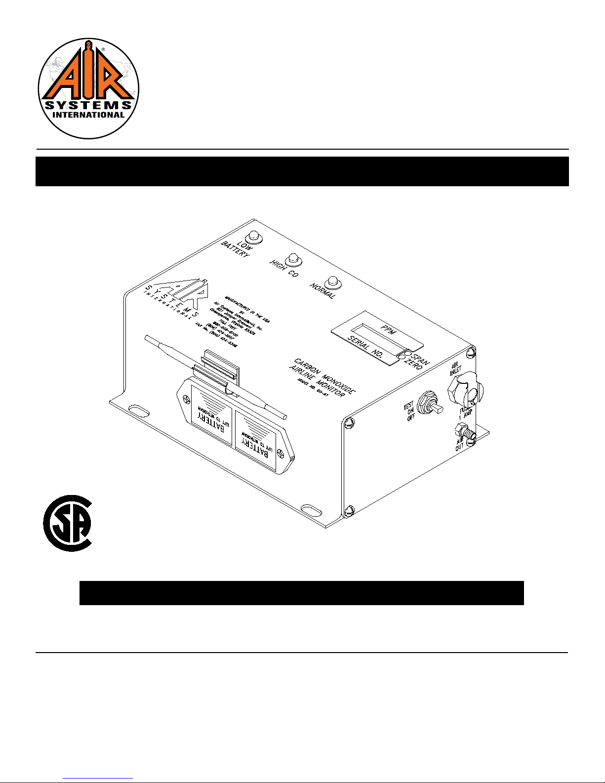
The monitor will analyze the air sample and display the CO concentration in parts per million (ppm). The system’s green
“NORMAL” operation light will illuminate and the red “HIGH CO” light will icker approximately every second when the CO
level is below 10ppm (5ppm Canadian). If the CO concentration level exceeds the alarm set point, the green “NORMAL”
light will turn off, the red “HIGH CO” light will illuminate, the audible alarm will sound, and the remote alarm connections
will energize. Once the CO concentration levels drop below the alarm set point, all alarm indicators will deactivate and the
unit will return to “NORMAL” operation.
Overview
Monitor Specications
Maintenance Items

4
NOTE: Model CO-91IS has the indicator lights and audible alarm mounted on bottom of housing and model CO-91ISLA
has the indicator lights mounted on top of housing with the audible alarm being mounted on the left endplate.
Carbon Monoxide Monitor System Components

5
ITEM # DESCRIPTION PART #
1 LCD Display MONC703
2Span Poten ometer MONC702A
3Alarm Set Point Poten ometer MONC702A
4Zero Poten ometer MONC702
5Air Sample Inlet Socket MONC001
6Air Sample Plug MONC002
7Air Exhaust Port MONC003
8On/Off /Test Switch MONC007
9CO-91IS/CO-91ISLA Faceplate Assembly CO-91EXFP
10 Faceplate/Endplate Screw MONC023
11 Main Circuit Board Assembly CO-91ISPCB
12 Power Supply Board CO-91EXPSB
13 Sensor Connector (Soldered To PCB) MONC509
14 Ba ery Box MONC006
15 9 Volt Ba ery ELB9V
16 Calibra on Tool MONC028
17 Audible Alarm (CO-91ISLA) ELLS008
18 Aluminum Housing CO-91AHOU
19 Led Socket MONC009LA
20 Yellow LED MONC008NS
21 LED Socket And Yellow LED CO-91LED
22 Red LED (CO-91ISLA) MONC035NS
23 Green LED (CO-91ISLA) MONC036NS
24 PPM/Serial No. S cker MONC031
25 Ba ery Box Connector (Soldered To PCB) MONC516
26 LED Connector (Soldered To PCB) MONC511
27 CO Sensor CO-91NS
28 CO Sensor Holder MONC810
29 CO Sensor Electrical Leads CO-91SL
30 90° Hose Barb MONC811
31 Audible Alarm (CO-91IS) ELLS004IS
32 Lamp Socket (CO-91IS) ELDS004
33 Clear Lens (CO-91IS) ELDS013
34 Red LED (CO-91IS) MONC004
35 Green LED (CO-91IS) MONC005
Carbon Monoxide Monitor System Components

6
STEP 1)
Check and replace 9 volt batteries if necessary.
These batteries provide a bias voltage to the
CO sensor. If the batteries are removed from the
monitor for 2 hours or more, a 1 hour restabilization
period is required before use.
Set-Up/Operaon
STEP 2)
Connect the air sample hose to the monitor.
STEP 3)
Place the “ON/OFF/TEST” switch in the “ON” posi-
tion. Allow 30 seconds for the display to stabilize.
If a reading other than “00” is displayed, calibration
of the monitor may be necessary. See calibration
procedure beginning on page 8.
STEP 4)
Adjust owmeter so ow ball hovers between 50 and 100
cc/min.
Monitor does not turn on Check and replace 9 volt batteries
Lights are ashing randomly Remove left endplate and check sensor connections.
Troubleshooting

7
Replacement sensors are shipped with a metal spring installed between the electrodes. Do not remove the clip until the
sensor is to be installed into the monitor.
Step 1)
Disconnect all external connections.
Remove CO monitor from the unit.
Step 2)
Remove the four screws from the moni-
tor’s left endplate.
Step 3)
Remove endplate to gain access to the
sensor cup.
Step 4)
Remove sensor from sensor cup and remove leads. Take the new
sensor and remove the metal spring. Reattach leads to the proper
colored terminals on the new sensor. Install new sensor into sensor
cup.
Step 5)
Reassemble monitor and reinstall in unit.
Connect all cables and air sample hose.
Allow monitor to stabilize 30 minutes to 1
hour and recalibrate.
SENSING
(RED)
REFERENCE
(BLUE)
UNUSED
CONTROL
(BLACK)
Sensor Replacement

8
CALIBRATION PROCEDURE
Do not use inert gases to zero the monitor. This will cause premature failure of the sensor.
CO Monitor Zero Adjustment
To zero the monitor, follow the steps below. Zero calibration gas should be used to properly “zero” the monitor
and assure that a valid calibration is achieved. If zero adjustment cannot be made as indicated, sensor replacement may
be necessary. After each monitor adjustment outlined in the steps, allow time for the changes to stabilize.
STEP 1)
Place the “ON/OFF/TEST” switch in the “ON” position.
STEP 8)
Allow digital readout to stabilize approximately 15-30
seconds.
STEP 10)
Turn the regulator off and disconnect the regulator from
the zero gas cylinder.
STEP 2)
Allow 30 seconds for the readout to stabilize. The green
indicator will illuminate.
STEP 3)
Hold the “ON/OFF/TEST” switch in the “TEST” position.
The following will occur:
Audible alarm will sound
Green LED will ash
Amber Low Battery indicator on monitor will
illuminate
Red LED will be on
This test ensures the circuitry is operable and continuity
to the sensor is proper. Release the switch.
STEP 4)
Remove the air sample inlet tube.
STEP 5)
Install regulator on the zero air cylinder reference gas.
STEP 7)
Attach the clear tubing with the male plug to the air sam-
ple inlet on the monitor.
STEP 6)
Turn the knob on the regulator counterclockwise to allow
the ow of gas thru the hose. Verify ow of gas thru the
hose via touch or sound.
STEP 9)
Adjust the “zero” adjustment screw (clockwise to increase
or counterclockwise to decrease) until a reading of “00” is
obtained.
Calibraon Procedure

9
CALIBRATION PROCEDURE
CO Monitor Span Adjustment
Use only 10-20ppm CO gas for calibration. Using a higher concentration may decrease accuracy at lower scale readings.
Note: 10ppm gas must be used to satisfy Canadian calibration requirements.
STEP 1)
Install regulator on the CO calibration gas cylinder.
STEP 3)
Connect the plug to the air sample inlet on the monitor.
STEP 2)
Turn the knob on the regulator counterclockwise to allow
the ow of gas thru the hose. Verify ow of gas thru the
hose via touch or sound.
STEP 4)
Allow digital readout to stabilize 15-30 seconds.
STEP 5)
Adjust the “span” adjustment screw (clockwise to in-
crease or counterclockwise to decrease) until the digital
readout reads the same as the concentration (ppm) as
printed on the calibration gas cylinder.
STEP 6)
Turn the regulator off and repeat the “zero” adjustment
procedure. The digital readout should return to a “00”
reading.
The monitor is now calibrated and should be
recalibrated monthly or if accuracy is question-
able. Check local requirements and recalibrate
as required.
Calibraon Procedure

10
Notes:

11
Notes:

AIR SYSTEMS INTERNATIONAL, INC.
829 Juniper Crescent, Chesapeake, Va, 23320
Telephone (757) 424-3967
Toll Free 1-800-866-8100
Fax No. (757) 424-5348
http://www.airsystems.com
Printed in the U.S.A. ©Copyright Air Systems International, Inc. 2018 All Rights Reserved
Manual No. MON025
Rev. 2 May 2018
This manual suits for next models
1
Table of contents
Other AIR SYSTEMS Measuring Instrument manuals