Air Techniques, Inc.
Page
6
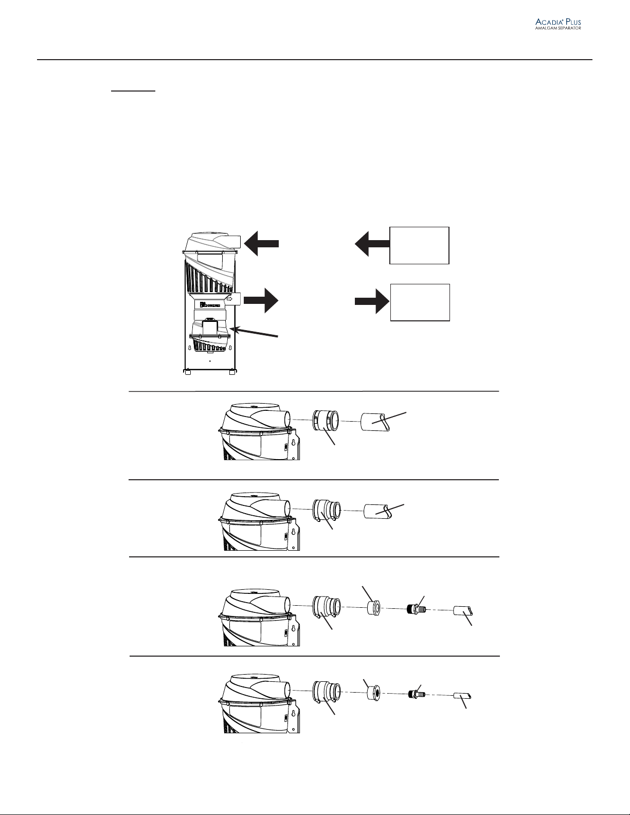
Important: Installation Accessory Hardware, P/N A1640 provides the necessary parts to connect to all
vacuum systems manufactured by Air Techniques. If the existing installations need different size
fittings or hose lengths, they must be provided by the installer.
Accessory Kit Components
The table below lists the supplied parts used to connect the Separator to new or existing vacuum systems.
UNPACKING AND INSPECTION
Unpacking
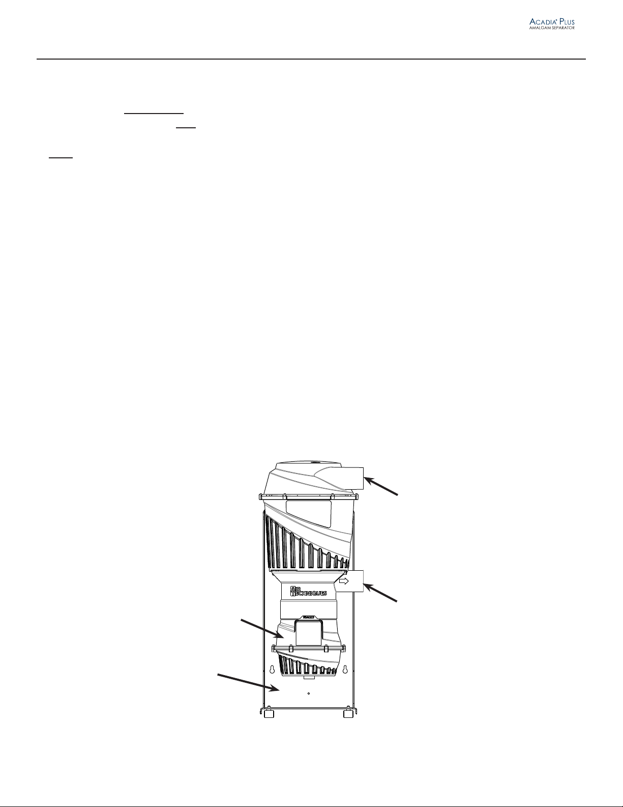
As shown by Figure 3, the Separator is shipped in a single carton containing the Separator assembly secured to
the Chassis/Mounting Bracket, the Collection Container, connection ttings, hoses and an installation accessory kit.
Unpack each component of the Separator and inspect for physical damage such as scratched panels, damaged con-
nectors, etc.
Included Separator Components
Each Separator consists of the components shown by Figure 3. Verify that all listed items were received. If any item is
missing, notify Air Techniques.
Figure 3. Acadia Plus Amalgam Separator Assembly Component Identification
Installation Accessory Kit, P/N A1640
Description Part No. Quantity
1½ inch ID Clear with Blue Helix Spiral Hose
Note: If more than 6 feet of hose is needed, order additional
P/N 54521 by the foot.
54521-6 6 Feet
2 inch ID Clear with Blue Helix Spiral Hose
Note: If more than 6 feet of hose is needed, order additional
P/N 54512 by the foot.
54512-6 6 Feet
2 inch to 2 inch No-Hub Flexible Coupling H5159 2
2 inch to 1½ inch No-Hub Flexible Coupling H5158 2
1½ inch SPG X 3/4 inch FNPT Reducing Bushing A1164 1
1½ inch slip X 1 inch FNPT, Reducing Bushing 55552 1
Leveling Feet 55323 4
Acorn Nut 60113-1 4
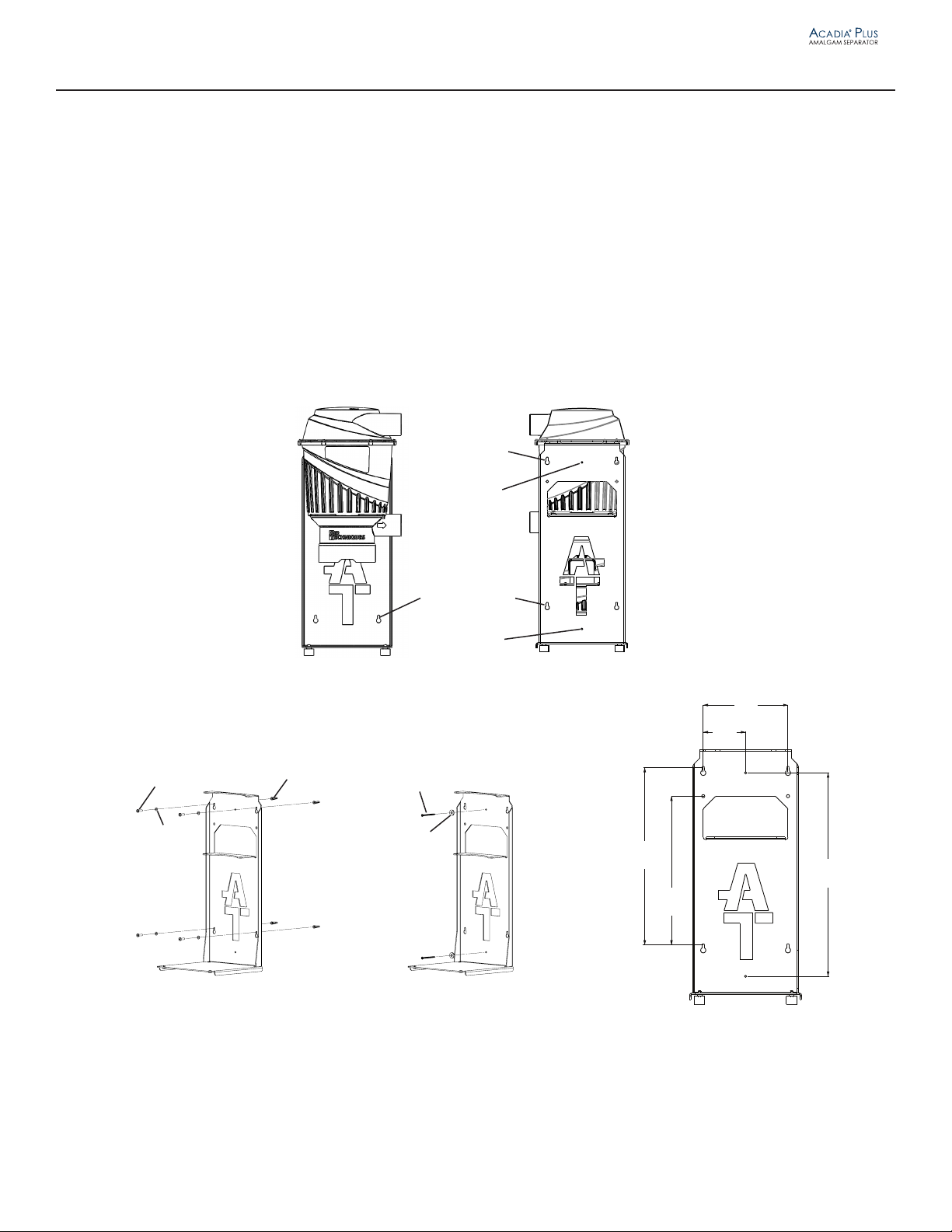
Wall Mounting Hardware
#10 X 1 inch plastic Anchor 30936 4
#12 X 3/8 Type A Phillips Pan Head 30935 4
#10 Flat Washer 30024 4
#8 Countersunk Washer 30023 2
#8 2½ inch Coarse Thread Drywall Screw 31905 2
Chassis/Mounting
Bracket
Amalgam
Separator
Assembly
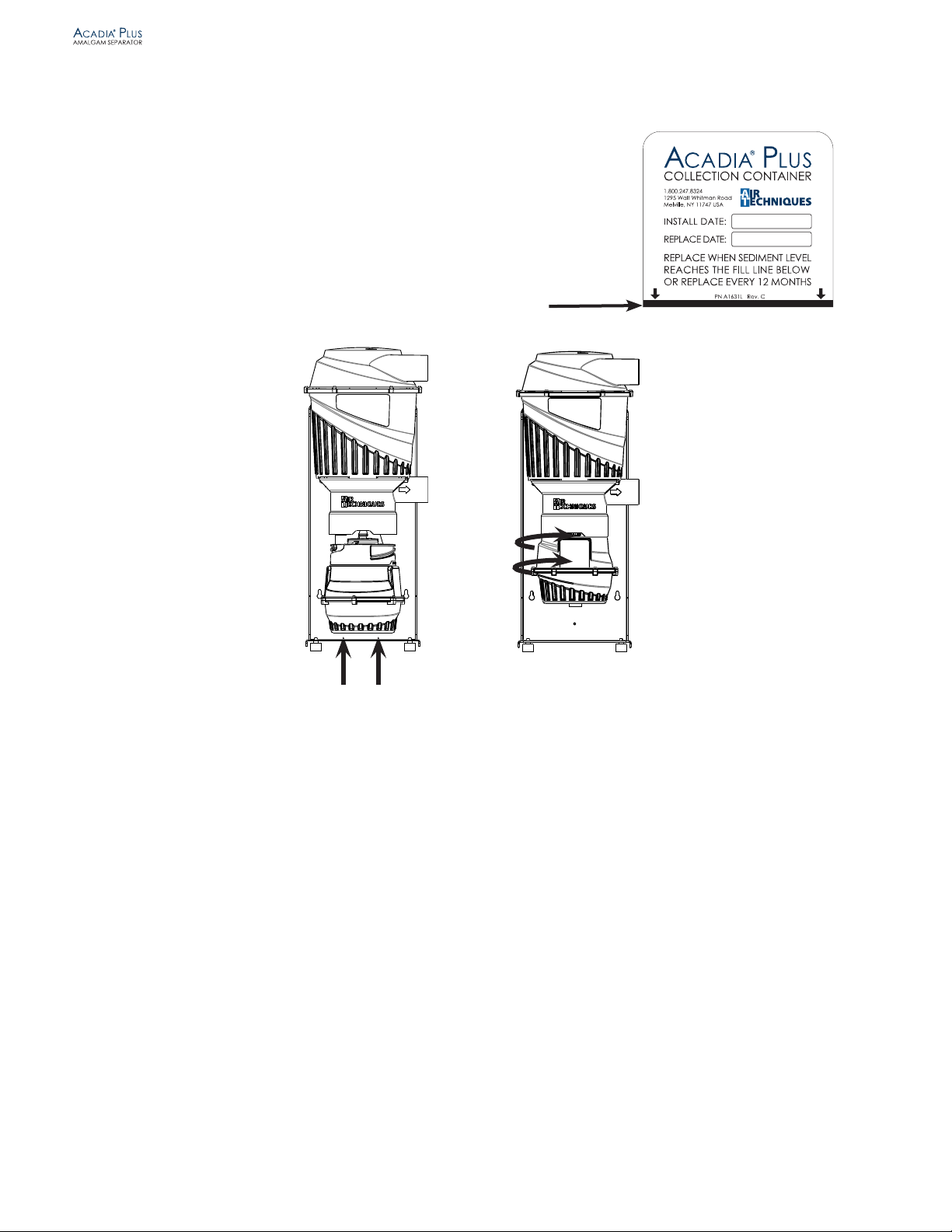
Collection
Container
Installation Accessory Kit,
P/N A1640.
Wall Mounting
Hardware,
See table below.