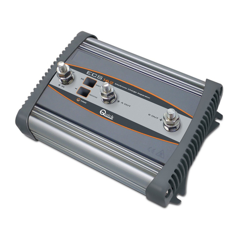
Quick QUICK6102A2 User manual

QUICK6102A2
Fume Purifying & Filtering System
Instruction Manual

2
Thank you for purchasing our equipment, please read this manual
carefully before using it make sure you understand its capabilities and
limitations. Keep this manual handy for future reference.

3
Content
Chapter 1 Safety instruction ........................................................................... 5
Chapter 2 Introduction ................................................................................... 5
Chapter3 Feature........................................................................................... 6
Chapter 4 Technical data ............................................................................... 7
Chapter 5 Operation description .................................................................... 7
5.1 Turn ON/OFF Procedure ....................................................................... 8
5.1.1 Turn ON Procedure ......................................................................... 8
5.1.2 Turn OFF Procedure ....................................................................... 8
5.2 Access Menu ...................................................................................... 8
5.3 Set menu ............................................................................................ 10
5.3.1 P-Filter Flow Menu ........................................................................ 10
5.3.2 M-Filter Flow Menu ........................................................................ 11
5.3.3 C-Filter Flow Menu ........................................................................ 12
5.3.4 Pipe Diameter Menu ...................................................................... 13
5.3.5 Communication Menu ................................................................... 13
5.3.6 Language Menu ............................................................................ 14
5.3.7 Changing Password Menu ............................................................ 15
Chapter 6 Maintenance ............................................................................... 15

4
6.1 Alarm Message ................................................................................... 15
6.2 Parts maintenance and changeable. ................................................... 17
6.3 Part Name ........................................................................................... 18

5
Chapter 1 Safety instruction
Before operating machine read this manual carefully.
Flammable and explosive objects or gas solvents are strictly prohibited in
the working area.
Do not side or upside down.
The alarm will occur if the filter limit volume exceeds preset value.
Unprofessional person can’t change arbitrarily. When maintenance,
please put seal smooth and button the hasp.
During maintenance and inspection of the machine, attention power
status and pull out the power plug of the machine.
Regularly inspect and maintain will increase durability and performance.
Use original spare parts from QUICK to replace defective ones.
Do not use or store this product where children can reach.
Chapter 2 Introduction
The unit is a Fume Purifying & Filtering System for cleaning of both particles
and gases. The unit is dual fuming arms design and during the process of
soldering, laser marking, laser carving, printing etcetera, to be used at
filtrating the harmful substances, such as hydrocarbon, cyanide etc.
For good efficiency, it designs a Triple-filter system: pre-Filter, medium filter
and main filter which including HEPA (high efficiency) filter and gas filter. The
pre-filter with large area ASHRAE and the medium filter can filter the bigger

6
powders for prolonging the main filter’s life. The HEPA cleans the gas and
powders filtering from the pre-filter and then output them to the gas filter,
which with the carbon and other chemical combination, filters off the
deleterious substance and then outputs the clean air.
Chapter3 Feature
1. Easy to install and working station clean and tidy.
2. Triple-filters design, remove hazardous substances to ensure health. And
the filters can be replaced separately.
3. Circulate air filter type, avoid indoor air to out, save energy, and meet
environmental standards.
4. High power brushless DC motor available, prolong the lifetime.
5. Low noise design.
6. Flow volume adjustable, and the arm customized.
Handle box
Power switch
Power socket
Communication port
Handle box power socket
Hasp button
Top component

7
Chapter 4 Technical data
Item Data
Voltage ★100-240V 50/60Hz
Power consumption 250W
Arm number 2
System Airflow(with filter component) 2*100m³/h
Filtering Efficiency (0.3um) 99.97%
Arm dimension φ75mm×1500mm
Stationary Pressure 2400Pa
Noise ≤65dB
Dimension 470mm×230mm×500mm
Weight 15.5Kg
★Note: Ensure that your power supply data agrees with the
information on the nameplate of the machine!
Chapter 5 Operation description
Warn:
●Do not artificially block the air inlet to damage the motor.
●Please immediately replaced the filter after blocking.
●Do not side or upside down, in order to prolong the unit lifetime.

8
Note:
●The hasp must be buttoned.
5.1 Turn ON/OFF Procedure
5.1.1 Turn ON Procedure
1. Connect 220V AC power line into power socket.
2. Connect handle box line into it’s socket.
3. Turn on the power switch after connect, the unit is in ON states when it is
powered on.
5.1.2 Turn OFF Procedure
1. Press “SET” key two times to save parameters.
2. Press “ON/OFF” key in the main menu to OFF the unit.
3. Disassemble the handle box power line.
4. Remove the power line from socket.
5.2 Access Menu
The main menu opens when the handle box is powered, see figure 5-2-1.
Press “
▷
,
◁
” key to page up and down(5-2-2), press “ON/OFF” key to turn
on /off the unit.

9
Figure 5-2-1 Figure 5-2-2
Press “SYS” key to enter into Password menu, see figure 5-2-3.
Figure 5-2-3
The default password is 000, press “SET” key to confirm after enter
password.
Press the “△” key once to increase the value by one digit, press and hold it
to continuously increase.
Press the “▽” key once to decrease the value by one digit, press and hold it
to continuously decrease.
Press the “
◁
” key to move the cursor to left and press the “
▷
” key to move

10
the cursor to right.
5.3 Set menu
Figure 5-3-1
The set menu will opens automatically when you enter the right password,
see figure 5-3-1. User can press “△or▽” key to select required item, and
press “SET” key to access menu.
A5.3.1 P-Filter Flow Menu
Figure5-3-1-1
1. In the P-Filter Flow Menu (see Figure5-3-1-1), user press “△or▽”key to
move cursor to required item.

11
2. Press “
◁
”or “
▷
”key to adjust the P-Filter limit volume, the range is
0-999km³.
3. Press “▽” key to move the cursor to the Clear indicator and press “△or▽”
to select.
4. Press “SET” key two times to save and press “BACK” to return.
NOTE: Only “YES” mode can reset the limit volume!
5.3.2 M-Filter Flow Menu
Figure5-3-2-1
1. In the M-Filter Flow Menu (see Figure5-3-2-1), user press “△or▽”key to
move cursor to required item.
2. Press “
◁
” or “
▷
”key to adjust the M-Filter limit volume, the range is
0-999km³.
3. Press “▽” key to move the cursor to the Clear indicator and press “△or▽”
to select.
4. Press “SET” key two times to save and press “BACK” to return.
NOTE: Only “YES” mode can reset the limit volume!

12
5.3.3 C-Filter Flow Menu
Figure5-3-3-1
1. In the C-Filter Flow Menu (see Figure5-3-3-1), user press “△or▽”key to
move cursor to required item.
2. Press “
◁
” or “
▷
”key to adjust the C-Filter limit volume, the range is
0-999km³.
3. Press “▽” key to move the cursor to the Clear indicator and press “△or▽”
to select.
4. Press “SET” key two times to save and press “BACK” to return.
NOTE: Only “YES” mode can reset the limit volume!

13
5.3.4 Pipe Diameter Menu
Figure5-3-4-1
1. In the Pipe Diameter Menu (see Figure5-3-4-1), user press “△or▽”key to
select pipe diameter.
2. Press “SET” key two times to save and press “BACK” to return.
NOTE: Only “75” and “25” two pipe diameter supplied!
5.3.5 Communication Menu
Figure5-3-5-1
1. In the communication Menu (see Figure5-3-5-1), press “
◁
” or “
▷
”key to
move the cursor to required item.

14
2. Press “△or▽”key to select address, the address range is 01-99 and the
default address is01.
3. Press “▽” key to move the cursor to the Clear indicator and press “△or▽”
to select baud rate, the baud rate is 9600,19200,38400 and 115200, the
default baud rate is 38400.
4. Press “SET” key two times to save and press “BACK” to return.
5.3.6 Language Menu
Figure5-3-6-1
1. In the Language Menu (see Figure5-3-6-1), user press “△or▽”key to
select language.
2. Press “SET” key two times to save and press “BACK” to return.
NOTE: Only “简体” , “繁体”and “English” three languages supplied!

15
5.3.7 Changing Password Menu
Figure 5-3-7-1
1. In the Password menu(see Figure 5-3-7-1), press “△or▽”key to adjust
number.
2. Press “
◁
” or “
▷
”key to move the cursor to required digit,
3. Press “SET” key to confirm after entering new password once.
4. Enter the same password in the Confirm Password area.
5. Press “SET” key two times to save and press “BACK” to return.
Chapter 6 Maintenance
6.1 Alarm Message
If an alarm has occurred, the message will be displayed in the handle box.
1. Display “E01”, see figure 6-1-1.

16
Figure 6-1-1
It indicates the brushless DC motor error.
Solution method:
① Turn off the unit and plug the power cord.
② Remove the top component, check the filter and air inlet for dirt.
NOTE: If has, please remove it.
③ Check the motor circuit.
NOTE: If you have any other problem, please contact us immediately!
2. Display “E02”, see figure 6-1-2.
Figure 6-1-2

17
It indicates the filter exceeds preset flow, please remove the filter and put a
new one.
Solution method:
① Turn off the unit and plug the power cord.
② Remove the top component.
③ Remove the dirt from net.
④ Remove the top seal rubber strip and set side.
⑤ Remove the damaged primary filter, medium filter, chemical filter.
⑥ Put the new filter as following 6.3 Part Name.
6.2 Daily Check
1. The unit, air inlet and handle box keep clean.
2. Replace filter when damaged.
3. Put the filter in the right position.
Note:
1. Make sure the primary filter spare side faces to air inlet during
maintenance.
2. The seal rubber strip must be level placed, or else, it cannot air proof and
reduce the suction.

18
6.3 Part Name
Parts name:
1: Hasp button
2:Unit case
3:Bottom seal rubber strip
4:Chemical filter (C-Filter)
5:Medium filter (M-Filter)
6:Primary filter (P-Filter)
7:Top seal rubber strip
8:Net for isolation dirt
9:Top component

19

20
QUICK INTELLIGENT EQUIPMENT CO., LTD.
ADD: NO.11, FengXiang Road, Wujin High-Tech Industrial Development
Zone, Jiangsu, China
TEL: 86-519-86225678
FAX: 86-519-86558599
POSTCODE: 213167
WEBSITE: www.quick-global.com
Table of contents
Other Quick Water Filtration System manuals
Popular Water Filtration System manuals by other brands

wavin
wavin minipek Installation, use and maintenance instructions

Circutor
Circutor AFQm instruction manual

UV Pure Technologies
UV Pure Technologies Hallett 30 instruction manual

EHEIM
EHEIM biopower 160 manual

Clarke
Clarke MF2 Instructions for use

Atlas Filtri
Atlas Filtri NEUTRAL MINI Installation, use and maintenance manual