Air Venturi ROVAIR Operator's manual

User Instruction Manual
RovAir
4500 PSI Portable Air Compressor
AV-ROVAIR4500
Ver. 1, 1/23

Contents
Parts Included.............................................................3
Setting up your RovAir Compressor...........................4
Operation Instructions: 110V or 220V outlet............5-6
Operation Instruction: 12V Battery ..........................7-8
Output Air Filter Replacement ....................................9
Troubleshooting........................................................10
Warranty ................................................................... 11
2
YOU AND OTHERS WITH YOU SHOULD ALWAYS
WEAR SHOOTING GLASSES TO PROTECT YOUR
EYES. READ ALL INSTRUCTIONS BEFORE USING. BUYER AND USER HAVE THE
RESPONSIBILITY TO OBEY ALL LAWS ABOUT THE PURCHASE, USE AND OWNERSHIP
OF THIS AIRGUN.
DANGER
!DANGER OF EXPLOSION!
Overlled compressed air cylinder
16
Do NOT exceed maximum ll pressure of 200 bar/ 2900 psi at room temperature!
IMPORTANT
!
17
18
19
IMPORTANT
THIS AIRGUN IS INTENDED FOR USE BY THOSE
16 YEARS OF AGE OR OLDER.
!
WARNING:
!
DO NOT INHALE DUST FROM LEAD PROJECTILES
OR PUT THEM IN YOUR MOUTH. WASH HANDS
AFTER HANDLING LEAD. SOME BBs MAY CONTAIN LEAD, A CHEMICAL KNOWN
TO THE STATE OF CALIFORNIA TO CAUSE CANCER AND BIRTH DEFECTS
(OR OTHER REPRODUCTIVE HARM).
DO NOT OVERFILL AIR CYLINDERS OR AIR GUN
TANKS, AS THIS CAN CAUSE SERIOUS INJURY OR
DEATH. NEVER SET THE OUTPUT PRESSURE/AUTO SHUT OFF ABOVE 4500 PSI (310
BAR).
WARNING
!
Do NOT exceed maximum ll pressure of your cylinder at room temperature!
YOU AND OTHERS WITH YOU SHOULD
ALWAYS WEAR SAFETY GLASSES TO
PROTECT YOUR EYES. READ ALL INSTRUCTIONS BEFORE USING.
IMPORTANT
!
© Air Venturi®/ www.airventuri.com / 216-292-2570
THIS PRODUCT IS MADE TO FILL PRE-CHARGED
PNEUMATIC (PCP) AIR RIFLES AND PISTOLS
DIRECTLY. THIS PRODUCT SHOULD NOT BE USED TO FILL STAND ALONE SCBA
OR SCUBA TANKS/CYLINDERS. FILLING SCBA OR SCUBA TANKS/CYLINDERS MAY
DAMAGE THE COMPRESSOR AND WILL VOID YOUR WARRANTY.
IMPORTANT
!

3
Parts Included
1. Male QD tting & test plug
2. Replacement burst disks
3. Spare O-ring
4. Replacement valve springs
5. Replacement seals
6. Jumper Cables
7. Replacement lters
9. 3-prong power cord (not pictured)
© Air Venturi®/ www.airventuri.com / 216-292-2570
Dual Cooling Fans
Filter Housing
Breaker Reset
Pressure
Release Valve
Carry Handle
On/Off Switch
Male Quick
Disconnect
Ouput Fitting Power Plug-in for
Jumper Cables
3-Prong Connector
61
4
5
2
3
7
Safety Valve
Burst Disc
Female Quick
Disconnect Fitting
Start/Stop Button
Gauge

4
© Air Venturi®/ www.airventuri.com / 216-292-2570
Setting up your RovAir Compressor
1) The cover must be removed. Before removing,
make sure the compressor is not connected to an
active electrical outlet. Start by removing each of
the 13 phillips head screws, with a phillips head
screwdriver turning them counter-clockwise (g. 1).
Once all screws are removed, lift the cover o of
the unit.
2) Locate the adjustment window on the power
converter. (g. 2a) Using an allen key, move the
switch to the 220V position. (g. 2b)
3) Replace the cover on the unit, and reinstall the
13 phillips head screws (g. 3)
4) Attach the hose and output lter to the compressor
via the female quick disconnect tting. The end with
the lter should be closest to the compressor (see
image for proper conguration) - (g. 4).
5) Make sure the connection between the female
quick disconnect on the hose and the male
connection on the compressor are tight.
3
1
2a
2b
4
Your RovAir comes pre-set to operate from an 110V outlet. Should you
choose to use the unit with a 220V outlet, complete the following steps.
CAUTION:
Always check and make sure the
collar on the female quick disconnect is in the forward
position and secure on the male tting you are
connecting it to. It is recommended that you check the
connection by attempting to pull the female and male
ends apart while the collar on the female tting is in
the forward position.
!

1) Plug the power cord into the RovAir (g. 1). DO NOT plug
the three prong connector into an active wall outlet yet.
2) Plug the 110V three prong connector into your wall outlet
(g. 2). Once plugged in, the fan on the power converter will
turn on.
NOTE: If connecting to a 220V outlet, an outlet adapter will be necessary to
use the included power cord.
3) Set the desired ll pressure via the dial on the top of the
pressure gauge (g. 3).
4) Close the bleed/pressure release valve by turning it
clockwise until it is tight (g. 4).
5) Connect the output hose to the device you wish to ll via
the female quick disconnect tting (g. 5).
PLEASE NOTE: If you are lling a PCP airgun from empty, you may need to
cock the gun before starting the ll process. Consult the owner's manual of
your airgun for further instructions.
6) Once these steps are complete, move the ON/OFF
switch to the ON (AC) position. The compressor fans
will begin to run. (g. 6).
7) Make sure the connection between the female quick
disconnect on the hose and the male connection on the
compressor are tight.
5
Operation Instruction: 110V or 220V outlet
1
2
4
© Air Venturi®/ www.airventuri.com / 216-292-2570
3
5
6
DO NOT OVERFILL AIR
CYLINDERS OR AIR GUN
TANKS, AS THIS CAN CAUSE SERIOUS INJURY OR DEATH.
NEVER SET THE OUTPUT PRESSURE/AUTO SHUT OFF
ABOVE 4500 PSI (310 BAR).
WARNING
!
CAUTION:
Always check and make sure the collar
on the female quick disconnect is in the forward position
and secure on the male tting you are connecting it to.
It is recommended that you check the connection by
attempting to pull the female and male ends apart while
the collar on the female tting is in the forward position.
!
CAUTION:
Always check and make sure the collar
on the female quick disconnect is in the forward position
and secure on the male tting you are connecting it to. It is
recommended that you check the connection by attempting
to pull the female and male ends apart while the collar on
the female tting is in the forward position.
!

6
Operation Instruction: 110V or 220V outlet
© Air Venturi®/ www.airventuri.com / 216-292-2570
7
8
9
10b
9) Once the fans are running, depress the START/STOP
button to begin lling (g. 7).
Note: You can stop the ll process at any time by depressing the START/
STOP button. If you do stop the ll for any reason, you MUST bleed the
pressure in the line before resuming lling. If you DO NOT bleed the
pressure in the line and just depress the START/STOP button to resume
lling, the RovAir will automatically stop after a few seconds of running.
10) Once the pre-set ll pressure is reached, the
compressor will stop.
NOTE: The cooling fans will continue to run.
11) Release/Bleed the pressure in the system by turning
the pressure release/bleed screw counter-clockwise
(g. 8).
12) Once the pressure is released and the pressure
gauge on the compressor reads 0 PSI/BAR, disconnect
the hose from the lled device by pulling back the collar
on the female quick disconnect tting and at the same
time, pulling it o of the male tting it was connected to
(g. 9).
13) To power down your RovAir, switch the ON/
OFF switch back to the OFF position (g.10a). The
compressor fans will turn o. Unplugging the three prong
connector (g.10b) from your 110V outlet will turn o the
power converter fan.
CAUTION:
Air and/or liquid may be released at
high velocity from the bottom of the unit. Keep ngers/
hands/eyes clear from the bottom of the unit when
opening the pressure release/bleed screw.
!
10a

1) Using the included jumper cables, connect the red
clamp to the positive post on the battery. Then connect
the black clamp to the negative post on the battery (g. 1).
2) Connect the cables to the compressor by inserting the
yellow plug into the outlet on the compressor (g. 2).
3) Set the desired ll pressure via the dial on the top of
the pressure gauge (g. 3).
4) Close the bleed/pressure release valve by turning it
clockwise until it is tight (g. 4).
5) Connect the output hose to the device you wish to ll
via the female quick disconnect tting (g. 5).
7
Operation Instruction: 12V Battery
© Air Venturi®/ www.airventuri.com / 216-292-2570
!CAUTION:
Always check and make sure
the collar on the female quick disconnect is in the
forward position and secure on the male tting you are
connecting it to. It is recommended that you check the
connection by attempting to pull the female and male
ends apart while the collar on the female tting is in the
forward position.
PLEASE NOTE: If you are lling a PCP airgun from empty, you may need to cock the gun before
starting the ll process. Consult the owner's manual of your rie for further instructions.
1
3
2
4
5
DO NOT OVERFILL AIR
CYLINDERS OR AIR GUN
TANKS, AS THIS CAN CAUSE SERIOUS INJURY OR
DEATH. NEVER SET THE OUTPUT PRESSURE/AUTO
SHUT OFF ABOVE 4500 PSI (310 BAR).
WARNING
!

8
© Air Venturi®/ www.airventuri.com / 216-292-2570
6
8
9
10b
Operation Instruction: 12V Battery
6) Once these steps are complete, move the ON/OFF
switch to the ON (DC12V) position (g. 6). The
compressor fans will begin to run.
7) Once the fans are running, depress the START/STOP
button to begin lling (g. 7).
Note: You can stop the ll process at any time by depressing the START/
STOP button. If you do stop the ll for any reason, you MUST bleed the
pressure in the line before resuming lling. If you DO NOT bleed the
pressure in the line and just depress the START/STOP button to resume
lling, the Nomad will automatically stop after a few seconds of running.
8) Once the pre-set ll pressure is reached, the
compressor will stop.
NOTE: The cooling fans will continue to run.
9) Release/Bleed the pressure in the system by turning
the pressure release/bleed screw counter-clockwise
(g. 8).
10) Once the pressure is released and the pressure
gauge on the compressor reads 0 PSI/BAR, disconnect
the hose from the lled device by pulling back the collar
on the female quick disconnect tting and at the same
time, pulling it o of the male tting it was connected to
(g. 9).
11) To power down your RovAir, switch the ON/OFF
switch back to the OFF position (g.10a). The
compressor fans will turn o. Unplugging the yellow
connector (g. 10b) from your RovAir will turn o the
power converter fan.
CAUTION:
Air and/or liquid may be released at
high velocity from the bottom of the unit. Keep ngers/
hands/eyes clear from the bottom of the unit when
opening the pressure release/bleed screw.
!
7
10a

9
Output Air Filter Replacement
1) Remove the lter and hose assembly from the
compressor unit by pulling back the collar on the female
quick disconnect tting and pulling the lter away from
the compressor (g. 1).
2) Find the seam in the lter housing (g. 2.1), twist the
large half counter-clockwise, unscrewing it until the unit
separates (g. 2.2).
3) Locate the cartridge lter inside of the large half of
the lter housing (g 3.1). Remove it with tweezers or by
puncturing it with an allen key and pulling it out of the
housing (g. 3.2).
4) Once the used lter is removed, replace it with a new
cartridge lter by pressing the new lter into the large
half of the housing (g. 4).
5) Reassemble the lter housing by screwing the small
and large halves together, turning the large half
clockwise until it is hand tight (g. 5).
6) Re-attach the female quick disconnect to the
compressor by pulling back on the collar on the female
while pressing it onto the male tting. Make sure the
collar is in the forward/locked position before attempting
to run the compressor.
1
2.2
3.1
3.2
4
2.1
5
© Air Venturi®/ www.airventuri.com / 216-292-2570
NOTE: It is recommended that you replace the Air Filter every 2-3 hours of use.
Should you require extra Air Filters, they can be purchased through Air Venturi
authorized retailers.

10
Troubleshooting
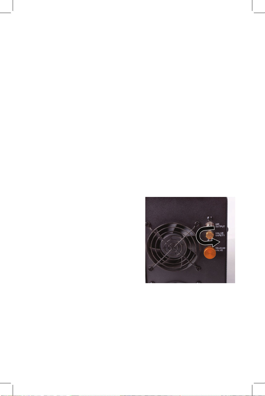
Issue - Burst disc failure
- Resolution: Should the burst disc fail
during use of the compressor, depress
the ON/OFF button and make sure the
compressor has stopped. Open the
Pressure Release Valve to let the
remaining air vent from the compressor.
Once you have veried the burst disc
has failed (there will be a hole in it) by
removing the burst disc retention screw
(pictured right), remove the broken burst
disc from the unit. You will nd
additional burst discs in the bag of spare
parts that comes with the compressor.
Install a new burst disc, and re-insert
the burst disc retention screw by turning
clockwise. If you do not have additional
burst discs, contact Air Venturi for
replacement at: 216-220-1180.
© Air Venturi®/ www.airventuri.com / 216-292-2570
In the unlikely event that your compressor malfunctions, DO NOT ATTEMPT
TO FIX THE PROBLEM YOURSELF. Please call Air Venturi’s service line so we
can address any issues or have you return the compressor for repair. Air
Venturi Service Line: 216-220-1180
Issue - Compressor will not start
- Resolution: Make sure the compressor is plugged into a functional electrical
outlet, and verify the plug into the wall and compressor are both properly
connected.
Issue - Compressor is not building pressure
- Resolution: Make sure the pressure release valve is closed. It should be hand
tightened. If closed and the compressor is still not building pressure, contact
Air Venturi by calling: 216-220-1180.
Issue - Compressor shuts o within 10 seconds of starting a ll
- Resolution: Start the ll with the bleed valve open, once the compressor has run
for a few seconds, close the bleed valve and your compressor should run normally.
If this does not resolve the issue, contact Air Venturi by calling: 216-220-1180.
Issue - Compressor shuts o before reaching desired pressure.
- Resolution: Make sure the Output Pressure Dial (Auto Shut O) is set properly.

11
Warranty
One Year Limited Warranty
Your Air Venturi Compressor is manufactured to the highest possible standards, using
quality materials to give a lifetime of service. In the unlikely event that there are any
defects in materials or workmanship in the rst twelve (12) months after retail purchase,
we will repair or replace the defective items under warranty.
What is covered?
• Replacement Parts and labor.
• Transportation charges to consumer for repaired product.
What is NOT covered?
• Any damage or faults caused by owner misuse, action or inaction.
• Transportation charges to Air Venturi for defective products.
• Damages caused by abuse or failure to perform normal maintenance.
• Any other expense.
• Parts subject to normal wear and tear.
• Consequential damages, incidental damages or incidental expenses including damage to
property.
This warranty is in addition to your statutory rights. Retain your sales receipt as proof of purchase.
NOTE: Some states do not allow the exclusion or limitation of incidental or consequential damages,
so the above limitation or exclusion may not apply to you.
Warranty claims:
Call Air Venturi at 216-220-1180 before returning any product.
Implied Warranties:
Any implied warranties, including the implied warranties of merchantability and tness for a particular
purpose, are limited in duration to one year from the date of retail purchase.
NOTE: Some states do not allow limitations on how long an implied warranty lasts, so the above
limitation may not apply to you.
To the extent any provision of this warranty is prohibited by federal, state or municipal law, which
cannot be preempted, it shall not be applicable. This warranty gives you specic legal rights, any you
may also have other rights, which vary from state to state and country to country.
Illustrations and photographs are for information purposes only and may not show the exact model
you purchased.
This warranty shall be invalid if the Compressor:
• Has been incorrectly disassembled, reassembled or maintained.
• Has been tted with non--Air Venturi parts.
• Has been abused, misused or improperly stored.
• Original purchase receipt cannot be presented.
© Air Venturi®/ www.airventuri.com / 216-292-2570

®
AIR VENTURI®
5135 Naiman Parkway, Cleveland, OH 44139
Ph: 216-292-2570 • fax: 216-373-0086
This manual suits for next models
1
Table of contents
Other Air Venturi Air Compressor manuals
Popular Air Compressor manuals by other brands

Schneider Airsystems
Schneider Airsystems CPM 310-10-20 WX Original operating manual

Coaire
Coaire CSOF-S3PL(H) Maintenance manual and parts list

EKOM
EKOM DK50 4VR/50/M user manual

DeWalt
DeWalt DXCM603 instruction manual

DeWalt
DeWalt Emglo D55151 instruction manual

DV Systems
DV Systems D20 Installation and start-up manual

Vixen Air
Vixen Air VXO4831DCF installation guide

Vixen Air
Vixen Air VXO4852DC installation guide

Profi-AirBrush
Profi-AirBrush ULTIMATE-1 operating instructions

Workzone
Workzone WZK 180 user guide

Michelin
Michelin MB 3100 U Instruction manual and safety instructions

Gude
Gude 260/10/24 ST Translation of the original instructions