Ridetech 81214001 User manual

Congratulations - your new LevelTow Helper Springs are quality products capable
of improving the handling and comfort of your vehicle. As with all products, proper
installation is the key to obtaining all of the benefits your kit is capable of delivering.
Please take a few minutes to read through the instructions to identify the components and
learn where and how they are used. It is a good idea to start by comparing the parts in
your kit with the parts list below. Components
Hardware
WARNING!
Do not inate this assembly when it is
unrestricted. The assembly must be restricted by
the suspension or other adequate structure. Do
not inate beyond 100 P.S.I. Improper use or
over ination may cause property damage or
severe personal injury.
81214001 1999-2006, 2007 CLASSIC GM 1500 2WD
2320
INSTALLATION INSTRUCTIONS
Congratulations - your new Air Helper Springs are
quality products capable of improving the handling and
comfort of your vehicle. As with all products, proper
installation is the key to obtaining all of the benefits your
kit is capable of delivering. Please take a few minutes to
read through the instructions to identify the components
and learn where and how they are used. It is a good idea
to start by comparing the parts in your kit with the parts
list below.
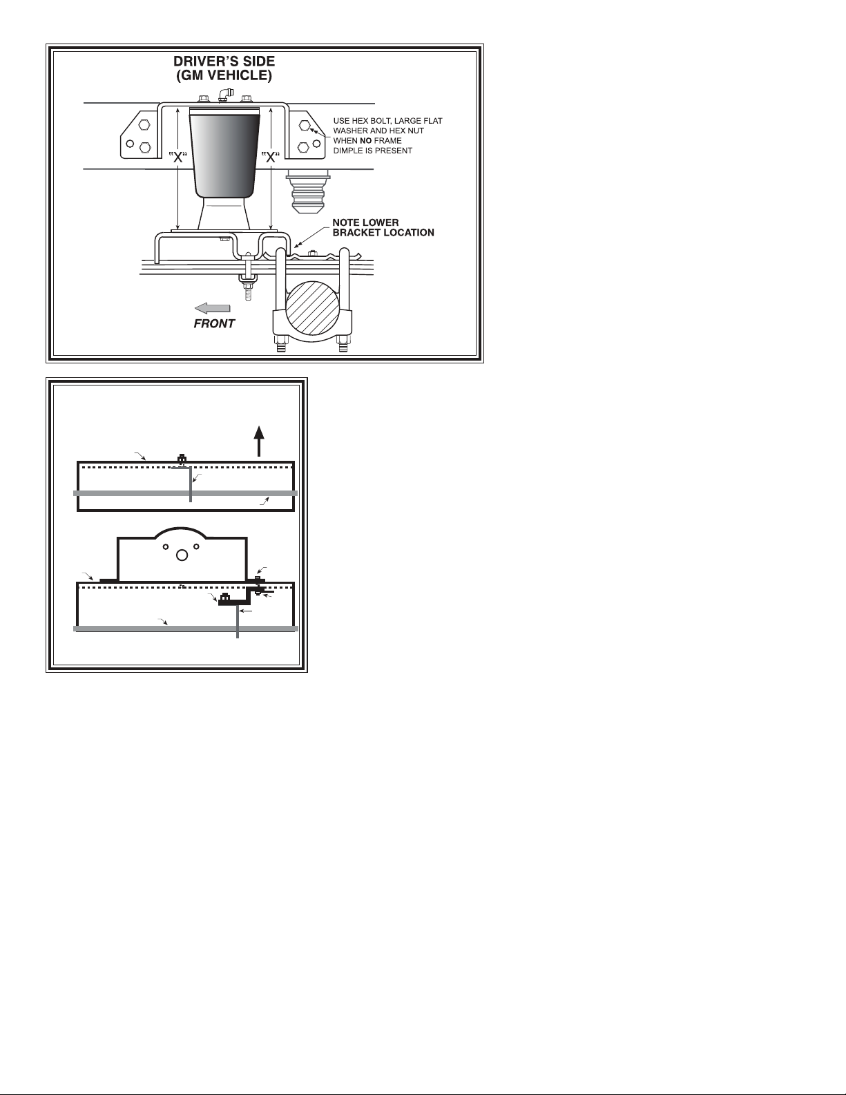
The heart of the kit is, of course, the air springs.
Remember that the air springs must flex and expand
during operation, so be sure that there is enough clearance
to do so without rubbing against any other part of the
vehicle.
Be sure to take all applicable safety precautions during
the installation of the kit. The instructions listed in this
brochure and the illustrations all show the left side of the
vehicle. To install the right side assembly simply follow the
same procedures.
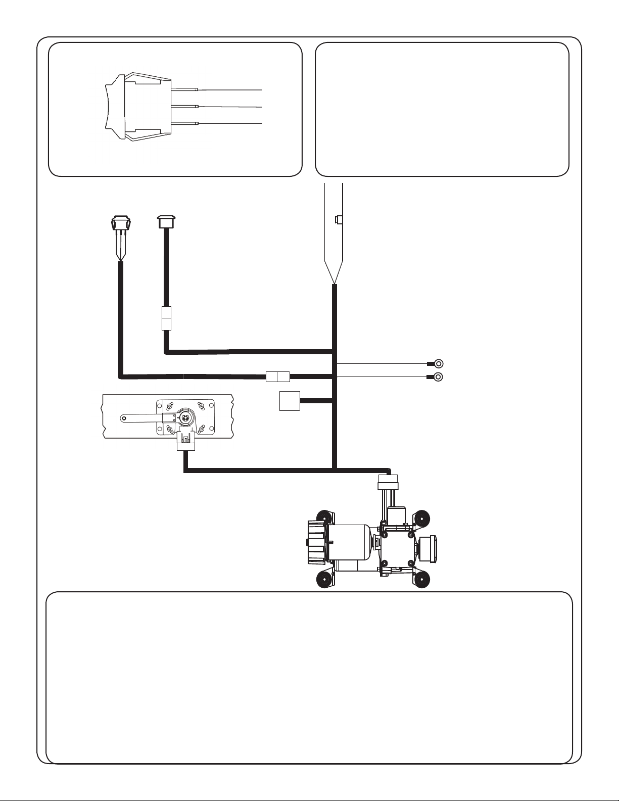
This kit includes inflation valves and air lines for each
air spring. This will allow you to compensate for unbal-
anced loads. If you would rather have a single inflation
valve system to provide equal pressure to both air springs,
your dealer can supply the optional "T" fitting.
IMPORTANT!
For your safety and to prevent possible damage to
your vehicle, do not exceed the maximum load
recommended by the vehicle manufacturer (GVWR).
Although your Air Helper Springs are rated at a maximum
inflation pressure of 100 psi, this pressure may allow you
to carry too great a load on some vehicles. Check your
vehicle owner’s manual or manufacture plate on
driver side door for maximum loads listed for your
vehicle.
When inflating your Air Helper Springs, add air
pressure in small quantities, checking pressure fre-
quently during inflation. The air spring requires much
less air volume than a tire and, therefore, inflates much
quicker.
21-8331 03-06 NAD-35133
WARNING:
Do not inflate this assembly when it is
unrestricted. The assembly must be restricted by
the suspension or other adequate structure. Do
not inflate beyond 100 psi Improper use or over
inflation may cause property damage or severe
personal injury.
PARTS LIST
AIR SPRINGS 9000 2
UPPER BRACKETS 5377 2
LOWER BRACKETS 5505 2
3/8" NUT PLATES 5245 4
DISK 5260 2
BRACKET STRAPS 5086 2
BRAKE LINE BRACKET(Ford) 5375 1
AIR LINE TUBING 1
3/8"-16 X 1-1/2" HEX BOLTS 8
3/8"-16 FLANGE LOCK NUTS 8
3/8"-16 X 3/4" HEX BOLTS 6
3/8" SPECIAL FLAT WASHERS 8
3/8"-16 X 3.62" X 3" BAIL CLAMP 4
5/16" FLAT WASHERS 4
PUSH TO CONNECT
INFLATION VALVES 3098 2
VALVE CAPS 2
PUSH TO CONNECT
ELBOW FITTINGS 3101 2
NYLON TIES 6
THERMAL SLEEVES 2
Installation of this kit requires a
minimum of 6" of clearance between the
tire side wall and the vehicle frame and a
1/2" of clearance around the air spring
when inflated.
ATTENTION:
Due to frame to tire clearance, this kit may not
fit vehicles with some brands of 5th Wheel or
Gooseneck hitches as this kit must be bolted to
the vehicle frame and not the hitch plates.
AIR SPRINGS 9000 2
UPPER BRACKETS 5377 2
LOWER BRACKETS 5505 2
3/8" NUT PLATES 5245 4
DISK 5260 2
BRACKET STRAPS 5086 2
BRAKE LINE BRACKET(Ford) 5375 1
3/8"-16 X 1-1/2" HEX BOLTS 8
3/8"-16 FLANGE LOCK NUTS 8
3/8"-16 X 3/4" HEX BOLTS 6
3/8" SPECIAL FLAT WASHERS 8
3/8"-16 X 3.62" X 3" BAIL CLAMP 4
5/16" FLAT WASHERS 4
NYLON TIES 6
THERMAL SLEEVES 2

3/8”-16
BAIL CLAMP

FRAME
BRAKE LINE
EXISTING
BRAKE LINE
CLIP
FRAME
BRAKE
LINE
EXISTING
BRAKE LINE
CLIP
UPPER
BRACKET
HEX
BOLT
NUT
PLATE
BRAKE LINE
RELOCATION
BRACKET
BRAKE CLIP RELOCATION
(FORD VEHICLE ONLY)
WHEEL
AIR LINE
PUSH-TO-CONNECT
INFLATION VALVE
FLAT WASHER
HEX NUT
VALVE CAP
BODY OF
VEHICLE
Figure "B"
Figure "E"
STEP 1 - PREPARE THE VEHICLE
First, measure the distance between the
tire and frame. If there is less than 6" of
clearance, do not proceed. There should be
no extra weight in the bed of the truck so that
the initial ride height of your air helper spring
kit will be correct. With the vehicle on a
solid, level surface chock the front wheels.
Raise the vehicle by the axle and remove the
rear wheels. After the removal of the wheels,
lower the vehicle so the axle rests on jack
stands rated for your vehicles weight. Remove
the negative battery cable.
THE“X”DIMENSION.
Throughout this manual we refer to an “X”
dimension.Thisistheinitial,un-inflatedover-
all height of the air spring. Both right and left
sides should be installed at the same height.
The “X” dimension on this air spring is 7"to
9". The air spring may require some stretching to achieve this dimension.
STEP 2 - PRE-ASSEMBLE THE KIT
Select one air helper spring from your kit. Install the upper bracket
by aligning the three holes on the air spring with the holes on the upper
bracket. Fasten the upper bracket to the air spring using the 3/8" x 3/4"
hex bolts as shown in Figure “A”. Install the air fitting as shown in
Figure “A”. Tighten the air fitting to make contact with the Teflon ring
and then tighten an additional 1/2 turn. No thread sealant is needed.
Insert the bail clamp into the lower bracket. Next, attach the lower
bracket and disk to the air spring using the 3/8"x 3/4" hex bolt (see
Figure “A”). Note: Finger tighten the bolt securing the lower bracket
and disk allowing the air spring to move freely. This will be tightened
after alignment in Step 6.
STEP 3 - ATTACH LOWER BRACKET TO LEAF SPRING
Place the assembly on the left side on top of the leaf spring stack
forward of the axle (see Figure “A” and “B”).Note the slight difference
in the lower bracket position on top of the leaf spring plate between Ford
and GM. Attach the lower bracket to the leaf stack using the bail clamp
(installed earlier), the bracket strap, and the flange lock nuts as shown in
Figure “A” and “B”. (Tighten to 15-20 ft. lbs.)
STEP 4- (GM TRUCKS)
CAUTION: The frame rails on some GM trucks have reinforcing ribs
used to strengthen to the frame rail. DO NOT drill through these ribs. If
the holes in the upper bracket align with these ribs, choose another hole
which is not on the rib and let the upper bracket rest against the rib. You
must use 2 holes on each side of the upper bracket. GM trucks with the
reinforcing ribs will require a flat washer between the upper bracket and
the frame to allow the upper bracket to rest squarely against the rib.
STEP 4– (FORD TRUCKS)
On FORD vehicles, unbolt the brake line bracket from the left frame rail.
Using the existing hardware, attach the brake line bracket onto the brake
line relocating bracket provided. This relocating bracket will be attached
to the inside of frame using the upper bracket mounting bolts. Relocation
is necessary to prevent the original brake line bolt from rubbing the air
spring. See Figures “A” & “C” for mounting.
AIR HOSE
INFLATION
VALVES
BUMPER
AIR
SPRINGS
Figure "C"
Figure "D"

S
TEP
5 – M
ARK AND DRILL HOLES IN THE FRAME RAIL
Visually align the air spring so that it is vertically straight and the upper and lower brackets are parallel. Place the
upper bracket so the top of the bracket is parallel with the top of the frame rail. (Note: The upper bracket should not
extend beyond the top of the frame rail.) see Figure “A” and “B”. Check the “X” dimension on both sides of the air
spring, these dimensions should be the same (refer to Figure “B”).Before drilling the holes make sure all electrical,
brake and fuel lines are cleared from the path of the drill. In order to prevent any damage to these lines it is recommended
that a piece of wood be placed between the frame rail and the existing lines during drilling. With the air spring assembly in
place, mark the upper left hole with a center punch. Drill the hole using a 3/8" drill bit.
S
TEP
6 – (A
LL
) A
TTACHING THE UPPER BRACKET
Your kit includes 3/8" nut plates as well as 3/8" flange nuts that will be used to attach the upper bracket to the
frame. These nut plates allow entry into the frame in the areas where it would be difficult to use a wrench. Once the
hole has been drilled, attach the upper bracket using a 3/8" x 1 1/2" hex bolt and a nut plate (finger tight). (On Ford
vehicles use the brake line relocating bracket) This will allow you to adjust the location of the upper bracket. Once
the positioning of the upper bracket is parallel with the lower bracket and the “X” dimensions are the same, drill the
remaining holes in the frame rail using the upper bracket as a template. Use the 3/8" x 1 1/2" hex bolts and nut plate
on the front portion of the frame rail. Use the 3/8" x 1 1/2" hex bolts, large flat washers (inside of the frame) and the
flanged hex nuts to fasten the upper bracket to the frame rail. Figure “A”. Tighten the bracket attaching bolts to 28
– 32 ft. lbs. Once the upper bracket is secure, align the bottom of the air spring side to side to ensure that it
is vertical. Tighten the bolt securing the lower bracket to the air spring.
S
TEP
7 - I
NSTALLATION OF THE RIGHT SIDE ASSEMBLY
Follow steps 1-5,
reversing all orientations,
for assembly and installation of the passenger’s side assembly. Both air helper
springs will install just to the front of the axle.
S
TEP
8 - I
NSTALL THE AIR LINE AND INFLATION VALVE
Uncoil the air tubing and cut it into two equal lengths. DO NOT FOLD OR KINK THE TUBING. Try to make the cut as square as
possible. Insert one end of the tubing into the elbow fitting installed in the top of the air helper spring. Push the tubing into the fitting as
far as possible.
Select a location on the vehicle for the air inflation valves. This can be on the bumper or the body of the vehicle, as long as it is protected
so the valves will not be damaged (see Figure “D”). Drill a 5/16" hole and install the air inflation valve using two 5/16" flat washers per
valve as supports (see Figure “E”). Route the tubing from the air helper spring to the inflation valve, avoiding direct heat from the engine,
exhaust pipe, and away from sharp edges. The air line tubing should not be bent or curved sharply as it may buckle with age. Secure
the tubing in place with the nylon ties provided. Push the end of the air line tubing into the inflation valve as illustrated (see Figure “E”).
S
TEP
9 - C
HECK THE AIR SYSTEM
Once the inflation valves are installed, inflate the air helper springs to 50 psi and check the fittings for air leaks with
an applied solution of soap and water. If a leak is detected, deflate the air spring by depressing the valve core. The tubing
can easily be removed from the fittings by pushing the collar on the fitting towards the body of the fitting while pulling
out the tube. Next, check the tubing connection to ensure that the air tubing is cut as square as possible and that it is
pushed completely into the fitting.
If a leak is detected where the air fitting screws into the air spring, gently tighten the air fitting into the spring
until the leak stops. Also, check the core of the inflation valve. This valve core can be tightened using the cap. Re-
inflate the air spring and check for leaks again if needed.
This now completes the installation. Install the wheels and torque the lug nuts to the manufactures specifications.
Raise the vehicle by the rear axle and remove the jack stands and lower the vehicle back onto the ground. Re-attach
the negative battery cable and remove the wheel chocks from the front wheels. Before proceeding, check once again
to be sure you have proper clearance around the air springs. With a load on your vehicle and the air helper springs
inflated, you must have at least 1/2" clearance around the air springs. As a general rule, the Air Helper Springs
will support approximately 30 lbs. of load for each psi of inflation pressure (per pair). For example, 50 psi of inflation pressure
will support a load of approximately 1500 lbs. per pair of air helper springs. FOR BEST RIDE use only enough air pressure
in the air helper springs to level the vehicle when viewed from the side (front to rear). This amount will vary depending on
the load, location of load, condition of existing suspension and personal preference
.
N
OTE
:
Too much air pressure in the air helper springs will result in a firmer ride, while too little air pressure will not allow the improvement
in ride and handling that is possible. TOPREVENT POSSIBLEDAMAGE MAINTAINA MINIMUMOF 10psi INTHE AIRHELPER
SPRINGS AT ALL TIMES. AFTER LOADING, YOU MAY USE UP TO 100 psi PER SIDE TO LEVEL THE TRUCK.
WHEN THE TRUCK IS LIFTED INTO THE AIR FOR SERVICE, DEFLATE BOTH AIR SPRINGS COMPLETELY.
AFTERWARDS, RE-INFLATE TO 10 psi PRIOR TO DRIVING.
OPERATING PRESSURE: MIN. - 10 PSI MAX (LOADED) - 100 PSI
Important:
In order for the air spring to function properly,
there must be a minimum of 1/2" of clearance
around the air spring.
STILL HAVE QUESTIONS?
Tech line hours
Monday - Friday 8Am - 6PM (EST) ....................... 812-482-2932

LevelTow Compressor System
Congratulations - your new LevelTow Compressor System is a quality product, that when used in conjunction with the
LevelTow helper Air Springs, is capable of improving the handling and comfort of your vehicle. As with all products, proper
installation is the key to obtaining all of the benefi ts your kit is capable of delivering. Please take a few minutes to read
through the instructions to identify the components and learn where and how they are used. It is a good idea to start by
comparing the parts in your kit with the parts list below.
Components: Part # QTY
Compressor Unit 31920022 1
Smart Sensor Height Sensor 31980006 1
Compressor Mounting Bracket 90002637 1
Smart Sensor Mounting Bracket 70014456 1
Sensor Linkage 31980011 1
Linkage Axle Bracket 70011429 1
Control Panel Bracket 70011439 1
Airline Fitting (mounted in compressor) 31957016 1
Main Activation Switch 35970000 1
Manual Control Switch 70011413 1
Main Wire Harness 31900051 1
Axle Bracket Clamp 99000005 1
1/4” TEE Fitting 31954400 1
1/4” Fitting for airsprings Straight / 90 Degree 31954000 / 31954201 2
20 amp fuse 90001922 1
Fuse Holder 90001924 1
10-12 Butt Connector for Fuse Holder 90001913 1
Ring Terminal for Main Power Hookup 90001916 1
Hardware:
#10 x 5/8” Phillips pan head - sensor to bracket 99104002 4
1/4”-14 x 1” Self Drilling Screw- Sensor to Frame 99254001 5
3/8-16 x 1” Thread Forming - Compressor Bracket to Frame 99373007 4
10-24 x 1 1/4” Maching Screw - Compressor to Bracket 99101007 4
10-24 Nylok Nut - Compressor to Bracket 99102002 4
#10 Flat Washer - Compressor to Bracket 99103001 8

The LevelTow Compressor System is an automatic leveling system, once it is turned on(button
illuminated blue) it will operate without any assistance.
The Smart sensor supplied with the compressor system will tell the system to infl ate or defl ate
to keep the vehicle level. It has a dwell range built in so that when the truck is going down the
road hitting small defects the system will be idle. It isn’t until the sensor gets out of this dwell
range for 18 seconds that the system will react.
The activation switch has to be illuminated blue for the system to work.
Activation Button
1. Before you install the compressor system,
you will need to have the helper Airsprings
installed. This will ensure that the LevelTow
linkage does not get in the way of the Air-
springs.
The rst step to doing the install, with the
vehicle at ride height, measure the lip of
the fender to the ground at the center of the
wheel and write it down.
Measurement_________________
This measurement will be used as a refer-
ence once you have the compressor system
installed.
2. Unpack the wiring for the LevelTow sys-
tem and lay it out. This will give you an idea
to where you can mount the components
without having to modify the wiring harness.
NOTE:
There is a wiring diagram on Page 7 to assist
you in component location.
Red Wire
20 Amp
Fuse
Activation
Switch
Manual
Inate/Deate
GREEN
BLACK
BLUE
White
4 pin plug
Black
10 pin plug Gray
4 pin plug
Relay
Black 3 pin plug Black Wire
Black Wire
System
Ground
Yellow Wire
Battery
(Needs to go to Battery under hood)
Keyed Power
(Should only have power with key on)
(these wires
can be attached
at the same point)
Page 2
Activation Button

3. Bolt the compressor to the bracket. Po-
sition the compressor on the Bracket in the
orientaion shown. Line up the holes in the
(4) Mounting Bushings with the (4) holes in
the Bracket. Install a #10 Flat Washer on
each of the (4) #10-24 x 1 1/4” Pan Head
Screws. Insert a Screw/Washer in each of
the 4 holes. Install a #10 Flat Washer on
the threads sticking through the bottom of
the bracket followed by a #10-24 Nylok Nut.
Tighten the hardware.
NOTE:
The diagram shows the position the com-
pressor goes onto the plate.
4. The compressor needs to be mounted
on the frame rail with the dryer up. Attach
the compressor bracket to the frame with (4)
3/8”-16 x 1” Thread Forming Bolts supplied in
the kit. Drill a 5/16” Hole for the bolts.
NOTE:
Before drilling any hole be sure to check and
see if there are any brake lines, fuel lines, or
wires on the other side of the surface you are
drilling.
5. The Axle bracket can be mounted in any
location on the axle tube to get the sensor
linkage to line up. The Axle mount should
be mounted on the axle so that the linkage
will line up from the axle mount to the sensor.
Keep this in mind when establishing the sen-
sor location.
Page 3

6. The next step will be to mount the sensor.
The Smart Sensor needs to be centered in
its travel at the trucks ride height to operate
properly. This can be done by cutting the
linkage rod to length. It can be ne tuned by
loosening the 4 sensor mounting screws and
twisting it in the mount and retightening the 4
screws. When the mounting and linkage is
done it should look like the diagram seen here.
7. The sensor needs to be mounted on the frame
rail with the wires pointing down. The arm will
need to swing up opposite the direction of the
wires as the suspension is being compressed.
Attach the sensor bracket to the frame with (4)
self drilling screws supplied with the kit.
NOTE:
The sensor can be mounted on the inside or
outside of the frame. Make sure the linkage
and arm can go through its entire travel without
hitting any obstructions
8. This diagram shows how the clamp sticks
through the axle bracket. Loosen the clamp
until it will open up and then slide it through the
bracket. The whole assembly can then be put
on the axle tube. Reinsert the end of the clamp
back into the adjuster and tighten the clamp
until the bracket is tight on the axle tube.
Page 4

9. With the sensor and the axle bracket
mounted, it is time to connect the 2 with the
supplied linkage. The linkage is a universal
length and will have to be cut to achieve the
necessary length for your application. To
do this it will be necessary to have the truck
sitting at its factory ride height. With the truck
at ride height center the sensor in its travel.
The rod can slide into each rubber rod end
up to 1”.
10. The linkage rod has barbs on the outside
of it to keep it in the end link. After you push
the ends in, they are diffi cult to pull back
out. Push the linkage into the ends a little
at a time until you get the desired length of
the linkage assembly. If for some reason
you must pull the rod out of the end, it is best
done by twisting the end while pulling on it.
11. Mount the control panel in a convenient
location. Install the Power Button and
Manual Control Rocker into the panel. The
Power Button gets installed into the round
hole. The nut that is on the button is used to
attach the button in the panel. The Rocker
Switch goes into the hole with the notch in it.
Align the tab on the switch with the slot and
push the switch into the hole until it snaps in
place. The rocker will only go into the hole
one way. You can also custom mount the
buttons if desired. They both use a 3/4” hole.
The hole for the manual switch will have to
have a slot for the tab
Page 5

Red Wire
20 Amp
Fuse
Activation
Switch
Manual
Inate/Deate
GREEN
BLACK
BLUE
White
4 pin plug
Black
10 pin plug Gray
4 pin plug
Relay
Black 3 pin plug Black Wire
Black Wire
System
Ground
Yellow Wire
Battery
(Needs to go to Battery under hood)
Keyed Power
(Should only have power with key on)
(these wires
can be attached
at the same point)
Red Wire - This wire needs to go straight to the Battery with the fuse holder installed within 18”
of the Battery
Yellow Wire - This wire needs to go to a switched 12 volt power source. This wire should only
have power when the key is on.
Black Wires - These wires go to a chassis ground. They can go to one of the screws attaching
the compressor to the frame.
Relay - Will need to be attached to the frame with a self drilling screw supplied in the kit..
12. Hook the wires up to the manual control
switch as shown in the diagram.
Green Wire-Manual Infl ate
Black Wire -Switch Supply
Blue Wire - Manual Defl ate
Page 6
GREEN
BLACK
BLUE
TOP

14. Once the system is installed you can ver-
ify the operation of the system by putting a
load on the truck. With a load on the truck
and the button illuminated blue, your fender
to ground measurement that you took on the
rst step should be the same. If it is higher
or lower you can adjust the height by loos-
ening the 4 screws that attach the sensor
to the bracket and twist in its mount. If ride
height can not be achieved by adjusting in
the bracket the linkage will need to be length-
ened or shortened to achieve the height you
need.
Page 7
AIR LINE
AIR
SPRINGS
COMPRESSOR
AIR LINE “T” FITTING
13. Uncoil the airline being careful not to kink or atten the line. Start at the Airspring fur-
thest from the compressor. Trim the airline so that the cut is clean and as square as possible.
Insert the end of the airline into the tting pushing it in as far as possible. Route the airline from
the airspring to the compressor keeping it away the exhaust pipe and sharp edges. If it is neces-
sary to run the line over a sharp edge, use a supplied thermal sleeve over the airline to protect
it. The sleeve is installed by sliding it over the airline to the area where the line needs protected.
The airline should not be bent or curved sharply, this can cause the line to buckle or kink.
Secure the airline in place using the Zipties provided in the kit. Once the rst airspring line is ran
to the compressor, trim o the excess and use it for the remaining air spring line to the compres-
sor. With both lines ran from the air spring to the compressor, install the “T” tting on the lines
and run the remaining side of the “T” tting to the compressor tting.
TIP: Wetting the end of the airline before sliding it into the tting makes it easier to install into
the tting.

Manual Operation:
The LevelTow Compressor System also has a manual control function. This function allows you to manually
infl ated or defl ate the system. To use the manual function you must rst turn the system o by pushing the
main power button. Once the system is turned o you can push the rocker switch up to infl ate or down to
defl ate. To put the system back in level mode push the main power switch to turn it back on.
Note:
If the Activation Button is illuminated blue and the manual button is pushed the truck will relevel itself. The
activation button has to be o for the manual control to be used and the truck remain at the height.
Troubleshooting:
If after installation you nd the system not functioning correctly, you may have the sensor operating the wrong
direction. You can verify this by turning the truck on and check that the activation button is illuminated blue.
Unhook one end of the linkage and move the sensor arm by hand. If when you move the arm down (Keep in
mind there is an 20 second delay) and the Air spring infl ates, the sensor is operating in the wrong direction.
You can x this problem without remounting the sensor by swapping the blue and green wires in the har-
ness at the sensor. To do this, with the truck turned o , simply unplug the harness from the sensor. Using
a small screwdriver pop the purple retainer out of the plug by prying up on each end of it. After removing the
retainer if you look into the end of the plug you will see a tang holding each wire terminal. Simply pry it down
just enough to release the terminals of the blue and green wires. Swap the blue and green wire postion and
reinstall the wires into the plug paying attention to the direction of the small tab on the wire terminal. This
tab will point to the center of the plug. Push the wire terminals into the plug making sure they catch on the
tang and reinstall the purple retainer. After plugging the sensor back in you can con rm correct operation by
turning the truck back on moving the sensor arm up, the Air spring should infl ate. If the system is functioning
correctly, shut the truck o and reattach the linkage.
STILL HAVE QUESTIONS?
Tech line hours
Monday-Friday
8AM - 6PM (EST)...........812-482-2932
Page 8
#82010009
RED
RED
BLACK
BLUE
GREEN
VIEW FROM WIRE SIDE
WIRE SIDE
SIDE VIEW
WIRE LOCATIONS AT HEIGHT SENSOR
This manual suits for next models
1
Table of contents
Popular Air Compressor manuals by other brands

Vmac
Vmac V400001 installation manual

Quincy Compressor
Quincy Compressor QR-25 Series instruction manual

Clarke
Clarke Ranger 7/500 Operation & maintenance instructions

HERKULES
HERKULES PRO-LINE Siltek+ Instruction manual for owner's use

DeWalt
DeWalt D55250 instruction manual

Nash Elmo
Nash Elmo G 400 Series operating instructions

Panasonic
Panasonic SD48C10JAU6 Specification sheet

Schulz
Schulz AIR PLUS 12V instruction manual

Draper
Draper 99074 manual

Sullair
Sullair 1107e Operators manual and parts lists

ULTIMATE SPEED
ULTIMATE SPEED UMK 10 A1 translation of original operation manual

IOWA MOLD TOOLING
IOWA MOLD TOOLING 14K160TH manual