Air Weigh LOADMAXX User manual

1
PN 901-0154-000 R0
Air-Weigh Customer Support: 888-459-3247
LoadMaxx
Installation Guide
Ford F-750 Trucks

2
Table of
Contents
TABLE OF CONTENTS.................................................................2
ABOUT LOADMAXX FOR F-750...................................................4
ABOUT INSTALLATION................................................................5
Overview.............................................................................5
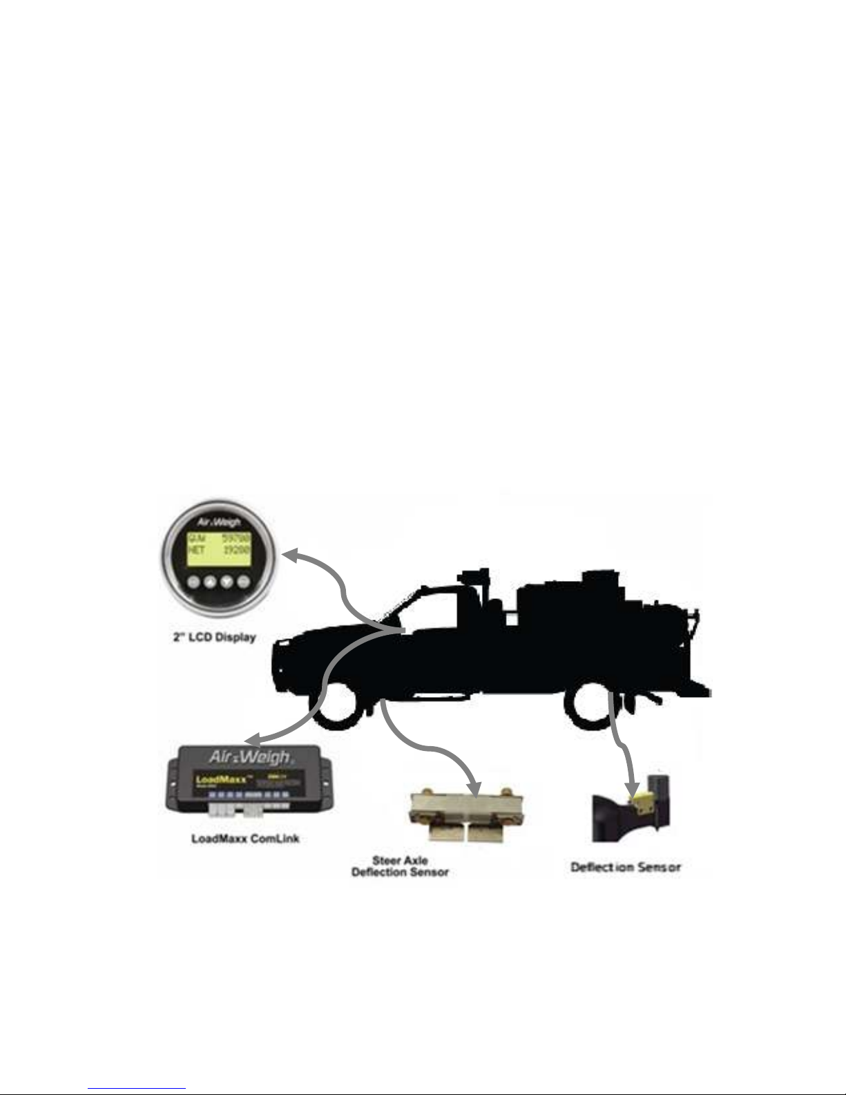
Installation Components...................................................... 5
TOOLS REQUIRED .......................................................................6
Optional Tools.................................................................. 6
INSTALLING THE STEER AXLE SENSOR BRACKET..................7
Preparing the Steer Axle Sensor Brackets........................... 7
Welding the Bracket ............................................................ 9
Adding a Protective Spray Paint Coating........................... 10
INSTALLING THE DRIVE AXLE SENSOR ..................................11
Assembling the Bracket to the Jig...................................... 11
Surface Preparation........................................................... 12
Welding the Bracket .......................................................... 13
Installing the Deflection Sensor ......................................... 14
INSTALLING THE COMLINK AND DISPLAY ..............................16
Preparing the Cab Display for Installation.......................... 16
Installing the Cab Display.................................................. 16
Mounting the ComLink....................................................... 17
Connecting Cables............................................................ 18
Table 2: Wiring Harness Hookup.................................... 18
Routing Cables.................................................................. 19
Securing Cables and Reassembling the Dash................... 19
INSTALLING AND ADJUSTING THE STEER AXLE SENSOR ....20

3
Installing the Deflection Sensor ......................................... 20
Setting the A/D Values ...................................................... 22
A/D Reading is BELOW 750........................................... 22
A/D Reading is ABOVE 1250.......................................... 23
Final Sensor Torque....................................................... 23
Steer Axle Finishing Touches............................................ 23
TESTING AND ADJUSTING THE DRIVE AXLE SENSORS.........26
A/D Reading is BELOW 750........................................... 27
A/D Reading is ABOVE 1250.......................................... 28
Final Sensor Torque....................................................... 28
LIMITED WARRANTY ................................................................. 30
PROCEDURE FOR WARRANTY CLAIMS...................................31

4
About LoadMaxx for F-750s
LoadMaxx is a weighing system for vehicles that works by using
deflection sensors and/or air pressure sensors. The sensors
measure suspension flex or air pressure changes and convert
that number into weight which is displayed in the truck cab..
Weight information, which includes axle group weights as well as
net and gross vehicle weights, are also displayed
The LoadMaxx scale includes a dash-mounted display, a
ComLink™ module, mounting cables, a deflection sensor with
mounting hardware for the steer axle, and a deflection sensor
with mounting hardware.
Please see the User Guide, included with your scale kit, to
calibrate your scale after installation.
Fig. 1: Major Components Location

5
About Installation
Overview
There are three major components of the LoadMaxx scale that
you will install:
•Electronics: dash-mounted display, ComLink module,
power cables and sensor extension cables
•Deflection sensor for the steer axle (vocational vehicles only)
•Deflection sensors for the suspension
Installation Components
For a full list of installation components, please see the Bill of
Materials, insert 905-0008-000 R0.

6
Tools Required
You will need the following tools to install the deflection sensors
on the steer and drive axles.
•Sander/grinder
•40-grit medium sandpaper
•Chalk or permanent marker
•Flat-blade screwdriver
•Combination wrench
•Torque wrench
•22mm socket and socket handle
•Enamel spray paint, any color
•Welder, MIG or ARC
•E7018 welding electrodes for ARC welders
•E70S-3 or E71T-1 welding wire for MIG welders
•309 Stainless Wire
•C-clamps
•Tape measure
Optional Tools
•Deflection sensor test box, available from Air-Weigh

7
Installing the Steer Axle Sensor
Bracket
Preparing the Steer Axle Sensor Brackets
1. Locate and mark the center of the steer axle (Fig. 2)
Fig. 2: Marking the Center of the Steer Axle
2. Using chalk or permanent marker, mark the top of the steer
axle 3 inches on either side of the center mark (6 inches in
total). Clean this area. If the axle is heavily caked with dirt or
grease, use Brakleen to remove the worst. Then clean the 6-
inch area using two of the alcohol pads supplied in the
installation kit (Fig. 3).
3. Using 40-grit medium sandpaper or a pneumatic grinder,
sand the 6-inch area until nothing remains but bare metal.
We recommend that you partially sand down the mold line as
well. See Fig. 3.
AW5800-1024
Center Mark

8
Fig. 3: Cleaning and Sanding the Steer Axle
Fig. 5: Cleaning the Bottom of the Bracket Assembly
4. Clean the underside of the bracket assembly with one of the
supplied isopropyl alcohol pads (Fig. 5).
5. Verify that the bracket contact pads fit into the sanded area
and that no axle paint is left under the pad. If there is any
paint at all that will be touching the brackets, sand until it has
been removed.
AW5800-1022
Alcohol Pad

9
Welding the Bracket
Air-Weigh takes no responsibility for damage or failure of
the steer axle due to improper welding
1. Place the new bracket assembly at the center of the axle
(Fig. 3). Use C clamps to hold the bracket in place. Make
sure you leave the alignment tool in the bracket assembly
while welding.
Fig. 3: Bracket assembly centered on axle
2. Fillet weld a full bead on the front and back edges of each
bracket piece, as per ANSI/AWS 2.4-79, AWS A5.4, AWS
A5.9 and AWS A5.22 standards (Fig. 4). Do NOT weld the
sides of the bracket, only the edges indicated on the next
page. Air-Weigh recommends that you use equipment similar
to Miller Shopmaster 300 AC/DC; AMP/VOLT setting of 22;
wire speed of 3.5; and a welding argon gas mixture of 75/25.
MIG welding should use 309 stainless wire. MIG welding will
use the same settings as the Miller Shopmaster noted above.

10
NOTE: Do not operate the vehicle while the alignment tool is
still in place.
Fig. 4: Welded axle and bracket
Adding a Protective Spray Paint Coating
To prevent the steer axle bracket from delaminating due to
corrosion, we recommend you spray paint around the base of
the bracket.
1. Using any enamel-based spray paint, paint around the base
of the bracket and over the glued section. Paint all bare
metal around the bracket completely.
2. Once the paint is dry, we recommend that you paint all
exposed metal a second time.
Fig. 10: Spray Paint Coating

11
Installing the Drive Axle Sensor
Assembling the Bracket to the Jig
1. Ensure the alignment pin of the bracket mounting jig is
touching the bracket (Fig. 11).
2. Tighten the supplied bolt to the jig assembly securely using a
wrench.
3. Repeat the above steps for the second bracket. Ensure all
edges are parallel and at the same height (Fig. 12).
Fig. 11: Assembling the Bracket to the Jig

12
Fig. 12: Completing the Bracket Assembly
Surface Preparation
1. Hold the bracket assembly firmly on the suspension and
mark the area inside the two large holes with a permanent
marker.
2. Remove the bracket assembly and set it aside.
3. Using a sander or grinder with 40-grit sandpaper, clean a
wide area around the marked areas so that only bare metal
is visible.

13
Welding the Bracket
1. Place the bracket assembly on the suspension. Make sure
the bare metal you sanded earlier lines up with the large
holes in the brackets.
2. Using two C-clamps, secure the bracket assembly to the
suspension (Fig. 12)
3. Using a MIG or ARC welder, tack-weld the two large holes
(top, bottom, left, right).
4. Then plug-weld the circumference of the two large holes in
the bracket assemblies ONLY.
5. Once the welds are COMPLETELY cooled, remove the
clamps.
6. Using enamel spray paint, paint all welded and sanded areas
to prevent oxidization.
7. Remove the two bolts from the bracket assembly and
remove the assembly jig.
Fig. 12: Clamping the bracket assembly to the suspension

14
Installing the Deflection Sensor
Once welding is complete, you can install the deflection sensor.
1. Clean the mounting surface for the deflection sensor and
bracket with Brakleen®. Ensure there is no paint between the
two surfaces to be mated.
2. Attach the deflection sensor to the beam with the cable
exiting toward the center mount. The word TOP should be
facing up (Fig. 13)
3. Place the hardened washers on the two bolts.
4. Place the bolts and washers through the holes in the
deflection sensor and then the slots in the brackets.
5. Place the two hex nuts on the bolts.
6. Hand-tighten each nut and bolt assembly.
Fig. 13: Installing the Deflection Sensor

15
NOTE: You must make sure that the frame rail will not hit
the top of the deflection sensor bracket when the
suspension is at maximum weight. As an approximation,
ensure that the travel between the frame stop and the
suspension is at least 1/2" more than the distance from the
top of the bracket to the frame rail above it.

16
Installing the Comlink and Display
Preparing the Cab Display for Installation
1. Select a location for the display (1) on the dash panel (5) with
at least 3 inches of clearance behind the dash panel (5) for
the unit and its connections. A higher dash position provides
better visibility.
2. Using a hole saw, cut a 2-1/8-inch hole (2) in the dash where
you will mount the display.
3. Remove the hex nuts (4) from the studs (6) on the back of
the display (1) to release the mounting bracket (3).
Figure 14: Display Preparation and Installation
Installing the Cab Display
1. Position the display (1) in the hole so that it appears level on
the dash.
2. Reinstall the mounting bracket (3) on the back of the display
(1) and secure with two nuts (4) on the display studs (6).
Tighten the nuts (4) and secure the display (1) to the dash
1
23
4
5
6
AW5800-1001

17
using 6 in-lbs. of torque. Do not over- tighten the
mounting bracket nuts (4).
Mounting the ComLink
1. Select a location behind the dash for the ComLink module,
ensuring there is adequate access to the scale and the
electrical connections.
2. The ComLink module should be oriented with the connectors
facing downward and installed by any one of the following
methods, using the hardware provided:
Use wire ties through the holes in the ComLink module
mounting ears to secure it to any appropriate wire harness
behind the dash. -OR -
Find a flat location where the ComLink module can be
attached using the 2-sided adhesive tape already in position
on the back of the ComLink module. Remove all dust, grease
or debris from the flat location using the supplied alcohol
pad. Remove one or both of the red strips from the back of
the ComLink module, exposing the adhesive tape. Place
the ComLink module against the cleaned flat area and push
hard enough to ensure adhesion. For best results, push the
ComLink module into place using steady force, being careful
not to crack the case. Using this method will make the
ComLink module more difficult to remove.
-OR -
Use self-tapping screws to secure the ComLink module to its
location.

18
Connecting Cables
The provided cables are used to connect the ComLink to the
vehicle’s electrical system, to the dash display unit, and, if
desired, to an alarm output.
Table 2: Wiring Harness Hookup
Power and Ground Table
White Wire Vehicle Chassis Ground
Blue/Black Wire with In-Line
Fuse 12VDC or 24VDC Ignition Hot Power
Gray Wire/Brown Wire Alarm output 1 and 2(same voltage as
vehicle power)
Black Wires Alarm ground Return 1 and 2
1. Connect the white wire to chassis ground.
2. Connect blue/black wire with inline fuse to the positive (+)
or “hot” side of the 12 VDC or 24 VDC ignition-on power
source. DO NOT connect directly to battery.
3. Connect the 10-pin plug of the power interface cable to the
ComLink module.
4. Connect both the 2-pin and the 4-pin plugs of the power
interface cable to the display.
5. When using an alarm, connect the alarm output wire and
the ground return wire to the desired device (buzzer, horn,
light, etc.).
NOTE: If you are using the optional printer, please see the
document Printer Installation Instructions (p/n 901-0105-000)
for information on connecting the printer to the ComLink.
The printer includes three cables. It and its cables can be
stored when it is not in use.

19
Routing Cables
1. Route the 20-foot steer extension cable and the 40-foot drive
extension cables along their respective axles and the frame,
and then through the cab firewall. Leave enough length for
sensor connections. If at all possible, route along an existing
wire harness. Be careful to avoid routing along pieces of the
frame that may move or cause wiring to rub.
2. Secure the cables loosely to the suspension using nylon ties.
3. Connect the extension cables to the ComLink module in the
dash. Drive cables should be connected to Ports A and B;
the steer cable should connect to Port C.
NOTE: Keep all cables a minimum of 12 inches from exhaust
piping or properly shield cables.
Securing Cables and Reassembling the Dash
1. Coil and secure any excess wire using nylon ties.
2. Tighten all nylon ties and trim.
3. Reassemble the dash assembly after all sensors have been
installed and sensor cables are connected. Ensure all
connections are tight.

20
Installing and Adjusting the Steer
Axle Sensor
Before you install the steer axle sensor, make sure the steer axle
adhesive is fixed and feels solid to the touch.
Installing the Deflection Sensor
1. Remove the alignment tool from the brackets. It should fit
loosely. Retain the two bolts and nuts to use when you
install the deflection sensor.
2. Clean the bracket channels with an alcohol pad.
3. Clean the sensor ends with the remaining alcohol pad.
4. Insert the steer axle sensor with its cable extending toward
the side of the vehicle where the sensor extension cable has
been routed to the firewall. Make sure the word “TOP” faces
up (Fig. 15).
Fig. 15: Inserting the Sensor into the Bracket
5. Align the steer axle sensor with the holes in the steer
axle bracket assembly.
Other manuals for LOADMAXX
4
Table of contents
Other Air Weigh Automobile Electronic manuals
Popular Automobile Electronic manuals by other brands

Philips
Philips GoSure ADR620 user manual

Volkswagen
Volkswagen 1K0 054 630 B installation instructions

Subaru
Subaru H001SAJ100 installation instructions

CrimeStopper
CrimeStopper CA-5014 user manual

Advent
Advent PSS100 - Standard Rear Only System installation manual

SungJin Techwin Co
SungJin Techwin Co MHF-R330BT user guide