Air 586MI User manual

PREFACE
Thank you for purchasing the 586MI system board. This document gives an aid to the configuration and installation of this
system board.
The information in this document is subject to change without notice.
This document contains information protected by copyright. ll rights are reserved. No part of this document may be used
or reproduced in any forms or by any means, or stored in a database or retrieval system, without prior written permission.
TRADEMARKS
Intel is a registered trademark of Intel Corporation.
IBM is a registered trademark of International Business Machines Corporation.
Microsoft is a registered trademark of Microsoft Corporation.
VES is a registered trademark of Video Electronics Standard ssociation.
ll other trademarks used in this manual are the property of their respective owners.
586MI System Board User's Manual Page 1

TABLE OF CONTENTS
CHAPTER 1: INTRODUCTION 4
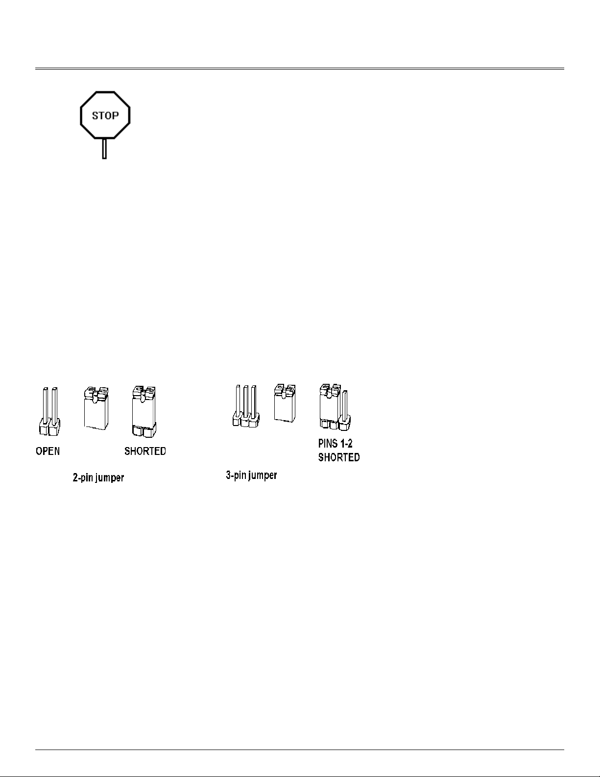
CHAPTER 2: JUMPERS & CONNECTORS 6
SYSTEM BOARD JUMPERS 6
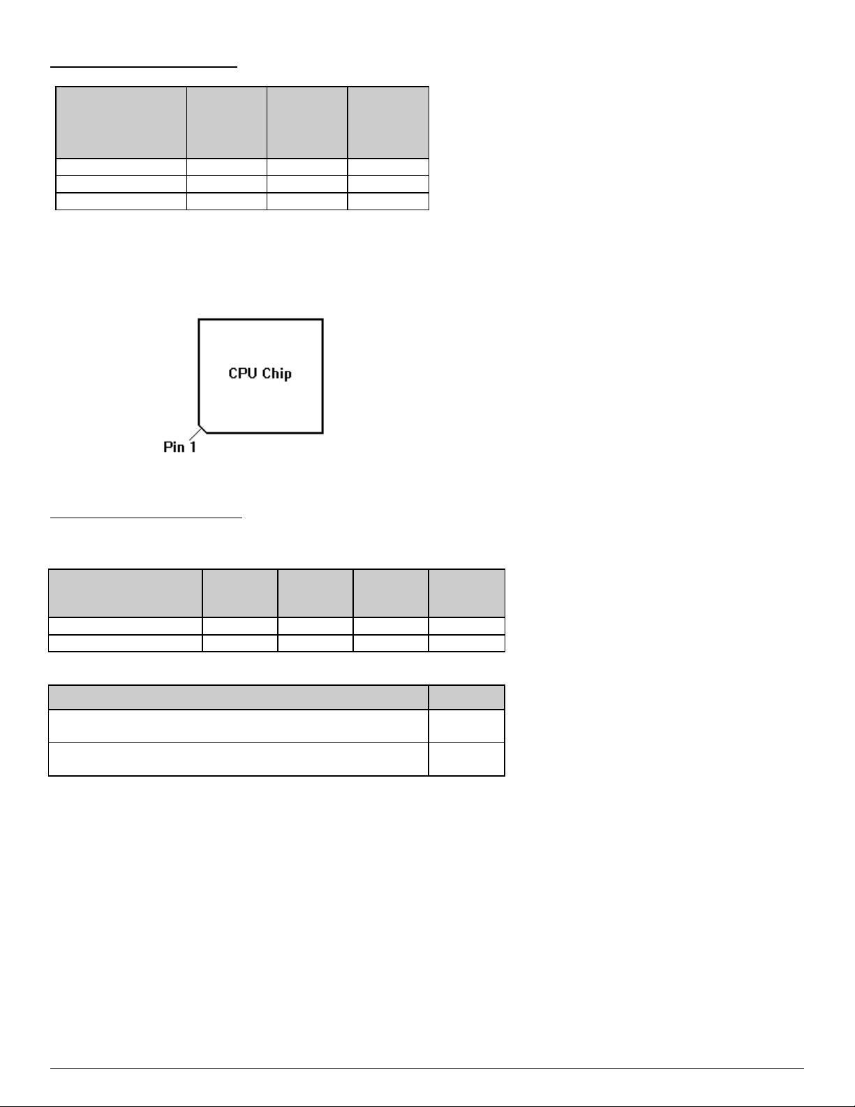
CPU Frequenc Jumpers 8
VESA Local Bus Jumpers 8
Cache Size Jumpers 9
Clear CMOS Data Jumper 9
Displa T pe Jumper 9
IDE Port Jumpers 10
Parallel Port Jumper 10
FLASH BIOS Jumper 10
SYSTEM BOARD CONNECTORS 11
Green PC Connector 11
Power Suppl Connectors 12
Ke board Connector 13
Power LED and Ke board Lock Connector 13
Speaker Connector 14
Reset Connector 14
Turbo Switch Connector 15
Turbo LED Connector 15
Parallel Port Connector 16
Serial Port 1 & 2 Connectors 16
Flopp Interface Connector 17
IDE Interface Connector 18
Harddisk Activit LED Connector 18
CHAPTER 3: HARDWARE INSTALLATION 19
THE DRAM SIMMs 19
Installing DRAM SIMMs 20
INSTALLING A VL-BUS CARD 21
INSTALLING EXTERNAL I/O CARD 22
EQUIPMENT REQUIRED 23
CHAPTER 4: BIOS SETUP 24
ENTERING SETUP 24
STANDARD CMOS SETUP 26
ADVANCED CMOS SETUP 27
ADVANCED CHIPSET SETUP 29
AUTO CONFIGURATION - BIOS DEFAULTS 30
AUTO CONFIGURATION - POWER-ON DEFAULTS 30
CHANGE PASSWORD 30
AUTO DETECT HARD DISK 31
HARD DISK UTILITY 31
WRITE TO CMOS AND EXIT 32
DO NOT WRITE TO CMOS AND EXIT 32
CHAPTER 5: VL-BUS IDE DRIVERS 33
DOS DRIVER INSTALLATION 33
WINDOWS 3.1 DRIVER INSTALLATION 33
APPENDIX A: KEYBOARD SPEED SWITCH 35
APPENDIX B: AMI BIOS HARD DISK TYPE 36
APPENDIX C: MEMORY MAPPING 37
APPENDIX D: AT I/O ADDRESS MAP 38
APPENDIX E: INTERRUPT ASSIGNMENTS 40
APPENDIX F: SPECIFICATION 41
Page 2 586MI System Board User's Manual

CHAPTER 1: INTRODUCTION
The 586MI system board adds to our product line high integration and cost effective solution without compromising
performance and quality. ll Pentium and Pentium Overdrive CPUs are supported on the 586MI system board. With top
speed at 66MHz and integrated 256K/512K Write-Back cache, the 586MI dramatically boosts system throughput for even
the most demanding applications.
CPU:
·Intel Pentium 60/66MHz and Pentium Overdrives.
Cache Memory:
·Supports 256K and 512K cache memory.
Main Memory:
·Supports 256Kx36, 512Kx36, 1Mx36, 2Mx36, 4Mx36, and 8Mx36 72-pin SIMM modules.
·Up to 128 MBytes on-board memory.
Slots:
·Three VES Local Bus (VL-Bus) Master slots.
·Six 16-bit IS bus slots.
·One 8-bit IS bus slot.
DE Port:
·Turbo/Normal selections for fast or slow IDE hard drives.
·Plug and play, replaces any non-intelligent IDE controller without reformatting the disk drives.
·lthough not required, DOS and Windows 3.1 software drivers are provided for maximizing performance.
586MI System Board User's Manual Page 3

Floppy Disk Controller:
·Fully IBM register set compatible.
·Supports up to two 3.5-inch or 5.25-inch floppy disk drives.
·Supports 360KB / 720KB / 1.2MB / 1.44MB densities.
·Floppy Disk Controller can be disabled.
Peripherals:
·Supports two Serial ports and one Parallel port.
On-Board Battery:
·3.6V/60m on-board battery.
Page 4 586MI System Board User's Manual

CHAPTER 2: JUMPERS & CONNECTORS
When working with the
586M , it is extremely
important that you avoid
static electricity. Always
ground yourself by wearing
a wrist or ankle strap.
Figures 1 on the next page shows the component layout of the 586MI system board with locations of the system board
jumpers and connectors. Note that most jumpers and connectors on the system board are labeled with proper names with
pin 1 marked as '1'. To avoid damaging the board and to have proper operation caution should be taken when connecting
these components.
SYSTEM BOARD JUMPERS
Jumpers are used to select between various operating modes. jumper switch consists of two, three, or four gold pins
projecting from the system board. Placing the plastic jumper cap over two pins connects those pins and makes a
particular selection. Using the cap to cover two pins in this way is referred to as shorting those pins. If the cap is not
placed on any pins at all, this is referred to as leaving the pins open.
Note: When you open a jumper, leave the plastic jumper cap attached to one of the pins so you don't lose it.
FIGURE
586MI System Board User's Manual Page 5

CPU Frequency Jumpers
CPU
FREQUENC
Y
JO1 JO2 JO3
60.000 OPEN SHORT OPEN
66.667 SHORT SHORT OPEN
50.000 OPEN OPEN SHORT
Care should be taken when installing the CPU into the Pin Grid rray (PG ) socket on the system board. Make certain
that pin 1 of the CPU chip is correctly aligned with pin 1 of CPU socket. The location of pin 1 on the CPU is denoted by a
small notch.
VESA Local Bus Jumpers
These jumpers allow any VL-Bus adapter to identify the speed of the system board.
VL-Bus Clock
Speed
JO5 JO6 JO7 JP19
33MHz (Default) SHORT OPEN OPEN OPEN
40MHz OPEN OPEN OPEN SHORT
High Speed Write JP18
System board runs one wait state write transfer. ll VL-
Bus adapters can operate in this mode.
SHORT
(Default)
System board runs zero wait state write transfer. Some
VL-Bus adapters may not be able to run this mode.
OPEN
Page 6 586MI System Board User's Manual

Cache Size Jumpers
Cache Size Jumper Selection
Cache
Size
JP1 JP2 JP3 JP4 JP5 JP6
64KB 1-2 1-2 1-2 OPEN OPEN OPEN
128KB 2-3 2-3 2-3 OPEN OPEN SHORT
256KB 1-2 1-2 1-2 OPEN SHOR
T
SHORT
512KB 2-3 2-3 2-3 SHOR
T
SHOR
T
SHORT
Cache Size and SRAM Locations
Cache
Size
Data Bank 0
U3 to U10
Data Bank 1
U18 to U25
64KB 8Kx8 None
128KB 8Kx8 8Kx8
256KB 32Kx8 None
512KB 32Kx8 32Kx8
Clear CMOS Data Jumper
The CMOS jumper JP15 is used to clear the system configuration data currently stored in the CMOS R M. ll system
setup information (hard disk type, date/time, etc...), stored in the CMOS, will be destroyed. This function would be useful if
you were to forget the user password for the system.
Function JP15
Normal CMOS Operation 2-3
(Default)
Clear CMOS Data 1-2
Display Type Jumper
Display Type JP14
Video display is VG , EG , or
Monochrome.
OPEN
(Default)
Video display is CG . SHORT
586MI System Board User's Manual Page 7

DE Port Jumpers
DE Enable/Disable JP30
Enable on-board VL-Bus IDE port. OPEN
(Default)
Disable on-board VL-Bus IDE port. SHORT
VL-Bus DE Recovery Time JP2
1
JP2
2
JP2
3
Speed 0: High speed IDE hard disk.
(Default Setting)
2-3 2-3 2-3
Speed 1: Medium speed IDE hard disk. 1-2 2-3 2-3
Speed 2: Slow speed IDE hard disk. 2-3 1-2 2-3
Parallel Port Jumper
Parallel Port JP32
Select interrupt line IRQ7 for Parallel port. 1-2
(Default)
Select interrupt line IRQ5 for Parallel port. 2-3
FLASH B OS Jumper
FLASH B OS Control JP13
Disable FL SH (optional) programming.
This is normal operation.
OPEN
(Default)
Enable FL SH BIOS programming.
Contents of system board BIOS can be re-
programmed.
2-3
Page 8 586MI System Board User's Manual

SYSTEM BOARD CONNECTORS
Green PC Connector
The Green PC connector can be used for power saving. Green PC feature is optional and can be enabled with special
Megakey keyboard controller and BIOS.
Descriptions W1
pins
W1
pins
Descriptions
No Connection.
1 6
Keyboard P12 to
control video card
VSYNC. This pin
should be connected
to pin 12 of VG
Feature connector.
Keyboard P12 to
enable/disable video
signals. This pin
should be connected to
pin 18 of VG Feature
connector.
2 7
Keyboard P13 to
control video card
HSYNC. This pin
should be connected
to pin 11 of VG
Feature connector.
Keyboard P13
(General Purpose).
When this pin is at low
level, it can switch
other system device to
stand-by mode for
saving power.
3 8
No Connection.
Keyboard P15
(General Purpose).
When this pin is at low
level, it can switch
other system device to
stand-by mode for
saving power.
4 9
No Connection.
Ground 5 10 No Connection.
586MI System Board User's Manual Page 9

Power Supply Connectors
The two Power Supply connectors are 6-pin T standard power connectors. Most power supplies have two six-wire
connectors, two of the wires on each connector are black. lign the two six-wire connectors so that the two black wires on
each connector are in the middle as shown below.
Pin Connector PS1 Connector PS2
1 Power Good Ground
2 +5 VDC Ground
3 +12 VDC -5 VDC
4 -12 VDC +5 VDC
5 Ground +5 VDC
6 Ground +5 VDC
Page 10 586MI System Board User's Manual

Keyboard Connector
The keyboard connector is a 5-pin, circular-type DIN socket. It is used to connect the system board keyboard interface to
any standard T-compatible keyboard (84 or 101 -key type keyboards). The pin assignments are listed below:
Pin Description
1 Keyboard Clock Signal
2 Keyboard Data Signal
3 Not Used
4 Ground
5 +5V Fused VDC
Power LED and Keyboard Lock Connector
The Power LED and Keyboard Lock connector (KEYLOCK) is 5-pin keyed BERG strip. It is used to connect +5 VDC
power to the power indicator LED at the front panel and connect security keyboard lock to the keyboard controller. This
allows you to switch off the keyboard and so provide limited security against casual intruders. The pin assignments are
indicated below:
Pin Description
1 LED Power
2 Key (No Connection)
3 Ground
4 Keyboard Lock
5 Ground
586MI System Board User's Manual Page 11

Speaker Connector
The Speaker connector (SPKR) is a 4-pin keyed BERG strip. It is used to connect an external 2-inch, 8-ohm speaker to
the system board to provide sound capability. The pin assignments are defined below:
Pin Description
1 Speaker Data Out
2 Key (No Connection)
3 Ground
4 +5 VDC
Reset Connector
The system RESET connector (RESET) is a 2-pin BERG strip. It is used to connect the push button reset switch located
on the front panel to the system board. System reset can be done by shorting pin 1 to pin 2 with the same effect as
turning the power off and then on again.
Pin Description
1 Ground
2 Reset Input
Page 12 586MI System Board User's Manual

Turbo Switch Connector
The Turbo switch (TURBO) is a 2-pin BERG strip. It is used to connect the front panel 2-position push switch to the
system board speed switching circuitry.
Pin Description
1 Turbo Speed
2 Ground
Notes:
- System runs at Turbo speed when pins 1 and 2 are shorted.
- System runs at Slow speed when pins 1 and 2 are open.
Turbo LED Connector
The Turbo LED connector, marked as 'TB/LED', is a 2-pin BERG strip. It is used to connect a CPU operating frequency
indicator LED from the front panel to the system board. The pin assignments are indicated below:
Pin Description
1 LED node
2 LED Cathode
586MI System Board User's Manual Page 13

Parallel Port Connector
The on-board parallel port connector (P R LL) is a 2x13-pin male header connector. The pin assignment is shown
below:
Pin Description Pin Description
1 -STROBE 14 - UTO FEED XT
2 Data Bit 0 15 -ERROR
3 Data Bit 1 16 -INIT
4 Data Bit 2 17 -SLCT IN
5 Data Bit 3 18 Ground
6 Data Bit 4 19 Ground
7 Data Bit 5 20 Ground
8 Data Bit 6 21 Ground
9 Data Bit 7 22 Ground
10 - CK 23 Ground
11 -BUSY 24 Ground
12 PE 25 Ground
13 SLCT 26 No Connection
Serial Port 1 & 2 Connectors
The serial port 1 and 2 connectors are the 2x5-pin male headers COM1 and COM2. Users should use a flex cable with a
9 or 25 -pin male D-subminiature receptacle at one end and a 2x5-pin female header at the other end to provide RS-232
serial interface. COM1 and COM2 addresses are automatically selected by on-board BIOS. If there is an external Serial
port adapter with COM1(3F8) and COM2(2F8), the on-board Serial port addresses will be changed to COM3(3E8) and
COM4(2E8) automatically. The pin assignment for COM1/COM2 is defined below:
Pi
n
Description Pi
n
Description
1 Carrier Detect (RLSD) 6 Receive Data (RXD)
2 Transmit Data (TXD) 7 Data Terminal Ready (DTR)
3 Signal Ground 8 Data Set Ready (DSR)
4 Request To Send (RTS) 9 Clear To Send (CTS)
5 Ring Indicator (RI) 10 No Connection
Page 14 586MI System Board User's Manual

Floppy nterface Connector
The on-board Floppy Interface connector (FLOPPY) is a 2x17-pin male header. This interface supports two 5.25" or 3.5"
floppy drives in any combination and also can be disabled if no floppy drives are present on the system.
Pin Description Pin Description
2 RPM 1 Ground
4 No Connection 3 Ground
6 No Connection 5 Ground
8 Index 7 Ground
10 Motor 1 9 Ground
12 Drive 2 11 Ground
14 Drive 1 13 Ground
16 Motor 2 15 Ground
18 Direction 17 Ground
20 Step 19 Ground
22 Write Data 21 Ground
24 Write Enable 23 Ground
26 Track0 25 Ground
28 Write Protect 27 Ground
30 Read Data 29 Ground
32 Head Select 31 Ground
34 Disk Change 33 Ground
586MI System Board User's Manual Page 15

DE nterface Connector
The on-board IDE Interface connector (IDE) is a 2x20-pin male header. This interface supports up to two IDE hard disk
drives on the system. This interface can also be disabled in the event that no hard drive is present or a separate hard
drive controller is installed on the system.
Pin Description Pin Description
2 Ground 1 IDE Reset/
4 Data 8 3 Data 7
6 Data 9 5 Data 6
8 Data 10 7 Data 5
10 Data 11 9 Data 4
12 Data 12 11 Data 3
14 Data 13 13 Data 2
16 Data 14 15 Data 1
18 Data 15 17 Data 0
20 No Connection 19 Ground
22 Ground 21 No Connection
24 Ground 23 I/O Write/
26 Ground 25 I/O Read/
28 LE 27 No Connection
30 Ground 29 No Connection
32 IOCS16/ 31 IDE IRQ 14
34 No Connection 33 ddress 1
36 ddress 2 35 ddress 0
38 IDE Chip Select 1/ 37 IDE Chip Select 0/
40 Ground 39 IDE ctive/
Harddisk Activity LED Connector
The hard disk activity LED connector (label as "HDLED") is a 2-pin keyed BERG strip. It is used to connect to front panel
hard disk LED.
Pin Description
1 LED node (+)
2 LED Cathode (-)
Page 16 586MI System Board User's Manual

CHAPTER 3: HARDWARE NSTALLAT ON
THE DRAM S MMs
The on-board DR M memory subsystem has four module mounting sockets which are divided into "banks" of two sockets
each. Sockets labeled SIM1 and SIM2 constitute bank 0. Sockets labeled SIM3 and SIM4 constitute bank 1. They
support 256Kx36, 512Kx36, 1Mx36, 2Mx36, 4Mx36, and 8Mx36 DR M SIMMs. DR M speed must be 60ns or 70ns.
You can configure the memory of the 586MI in a variety of ways as shown below.
Total
Memor
y
S M1 &
S M2
S M3 &
S M4
2MB 256Kx36 None
4MB 256Kx36 256Kx36
6MB 256Kx36 512Kx36
10MB 256Kx36 1Mx36
18MB 256Kx36 2Mx36
34MB 256Kx36 4Mx36
66MB 256Kx36 8Mx36
4MB 512Kx36 None
8MB 512Kx36 512Kx36
12MB 512Kx36 1Mx36
20MB 512Kx36 2Mx36
36MB 512Kx36 4Mx36
68MB 512Kx36 8Mx36
8MB 1Mx36 None
16MB 1Mx36 1Mx36
24MB 1Mx36 2Mx36
40MB 1Mx36 4Mx36
72MB 1Mx36 8Mx36
16MB 2Mx36 None
32MB 2Mx36 2Mx36
48MB 2Mx36 4Mx36
80MB 2Mx36 8Mx36
32MB 4Mx36 None
64MB 4Mx36 4Mx36
96MB 4Mx36 8Mx36
64MB 8Mx36 None
128MB 8Mx36 8Mx36
nstalling DRAM S MMs
When working with DRAM
S MMs, it is extremely
important that you avoid
static electricity. Always
ground yourself by wearing
a wrist or ankle strap.
1. The SIMM module should face to the right with pin 72 next to the power supply connectors.
2. Insert the SIMM at a 45 degree angle, tilted towards IS slots.
586MI System Board User's Manual Page 17

3. Gently push the SIMM to an upright position until it "snaps" into place.
4. Repeat above steps until the entire bank is filled.
Page 18 586MI System Board User's Manual

NSTALL NG A VL-BUS CARD
Carefully follow these steps to install a VL-Bus card:
1. Turn off your computer and unplug the power cord.
2. Turn off the power to all peripheral devices, such as your printer.
3. Disconnect the cables from the back of the system in order to give more room to work. Note how all cables are
connected prior to disconnection.
4. Remove the computer's cover.
5. Choose an unused VL-Bus slot.
6. Setting the VL-Bus card according to its user's manual.
7. Holding the card at the center of the top edge, gently push straight down with equal pressure at both ends.
8. Replace the screw to hold the card into place.
9. Replace and secure the system cover.
10.Reconnect all the wires and cables.
NSTALL NG EXTERNAL /O CARD
The BIOS on 586MI automatically detects external I/O devices. It will arrange the on-board I/O addresses accordingly to
prevent any address conflict.
Serial Ports:
The on-board Serial port 1 (labeled as COM1) address can be set to 3F8(COM1), 3E8(COM3), or Disabled.
The on-board Serial port 2 (labeled as COM2) address can be set to 2F8(COM2), 2E8(COM4), or Disabled.
The 586MI BIOS can detect external Serial port addresses and sets different addresses for the on-board Serial ports or
disables them entirely. User's responsibility is to select the Serial port addresses on the external I/O card. There are no
jumpers on 586MI to be changed.
Parallel Ports:
The on-board Parallel port (labeled as P R LL) address can be set to 378(LPT1), 278(LPT2), or Disabled.
586MI System Board User's Manual Page 19

The 586MI BIOS can detect external Parallel port addresses and sets different address for the on-board Parallel port or
disables it. User's responsibility is to select the Parallel port address on the external I/O card. There are no jumpers on
586MI to be changed.
Game Port:
If an external Game port is installed and enabled, the on-board Game port will be disabled.
DE/Floppy Ports:
If there is an external IDE and Floppy card installed, the on-board IDE and Floppy ports will be disabled automatically.
User's responsibility is to short jumper JP30 on 586MI.
Page 20 586MI System Board User's Manual
Table of contents
Other Air Motherboard manuals