Air 486SH User manual

PREFACE
Thank you for purchasing the 486SH system board. This document
gives an aid to the configuration and installation of this system board.
The information in this document is subject to change without notice.
This document contains information protected by copyright. ll rights are
reserved. No part of this document may be used or reproduced in any
forms or by any means, or stored in a database or retrieval system,
without prior written permission.
TRADEMARKS
Intel is a registered trademark of Intel Corporation.
IBM is a registered trademark of International Business Machines
Corporation.
Microsoft is a registered trademark of Microsoft Corporation.
VES is a registered trademark of Video Electronics Standard
ssociation.
ll other trademarks used in this manual are the property of their
respective owners.
486SH System Board User's Manual Page 1

TABLE OF CONTENTS
CHAPTER 1: INTRODUCTION 4
CHAPTER 2: JUMPERS & CONNECTORS 5
SYSTEM BOARD JUMPERS 5
CPU External Cl ck Jumpers 7
CPU Type Jumpers 7
Cache Size Jumpers 8
VESA L cal Bus Jumpers 8
Clear CMOS Data Jumper 9
Display Type Jumper 9
Green PC Jumper 9
SYSTEM BOARD CONNECTORS 10
P wer Supply C nnect rs 10
External Battery C nnect r 11
Keyb ard C nnect r 11
P wer LED and Keyb ard L ck C nnect r 12
Speaker C nnect r 12
Reset C nnect r 13
Turb Switch C nnect r 13
Turb LED C nnect r 13
Green PC C nnect rs 14
CHAPTER 3: INSTALLATION 15
THE DRAM SIMMs 15
Installing DRAM SIMMs 16
INSTALLING A VL-BUS CARD 17
EQUIPMENT REQUIRED 18
CHAPTER 4: BIOS SETUP 19
ENTERING SETUP 19
STANDARD CMOS SETUP 21
ADVANCED CMOS SETUP 22
POWER MANAGEMENT SETUP 26
AUTO CONFIGURATION - BIOS DEFAULTS 26
AUTO CONFIGURATION - POWER-ON DEFAULTS 26
CHANGE PASSWORD 26
AUTO DETECT HARD DISK 27
HARD DISK UTILITY 28
WRITE TO CMOS AND EXIT 28
DO NOT WRITE TO CMOS AND EXIT 28
CHAPTER 5: KEYBOARD HOT KEYS 29
SYSTEM SPEED 29
SYSTEM SECURITY LOCKING 29
SYSTEM POWER DOWN MODE 29
PASSWORD STATE 30
APPENDIX A: AMI BIOS HARD DISK TYPE 31
Page 2 486SH System Board User's Manual

APPENDIX B: MEMORY MAPPING 32
APPENDIX C: AT I/O ADDRESS MAP 33
APPENDIX D: INTERRUPT ASSIGNMENTS 35
APPENDIX E: ENVIRONMENTAL SPECIFICATION 36
486SH System Board User's Manual Page 3

CHAPTER 1: INTRODUCTION
The 486SH system board adds to our 486 product line high integration
and cost effective solution without compromising performance and
quality. With top speed at 50MHz and integrated 64K/128K/256K Write-
Back cache, the 486SH dramatically boosts system throughput for even
the most demanding applications. The 486SH offers features and
functionality exceeding any other system board in its class, including:
CPU:
·Intel i486DX, i486DX2, i486SX, i487SX, P24T, and Overdrives.
Cache Memory:
·Supports 64K/128K/256K cache memory.
Main Memory:
·Supports 256Kx9, 1Mx9, and 4Mx9 SIMM modules.
·Up to 32 MBytes on-board memory.
S ots:
·Three 32-bit VES Local Bus slots.
·Six 16-bit IS bus slots.
·One 8-bit IS bus slot.
Green PC:
·CPU clock-slow-down and monitor shut-down features.
On-Board Battery:
·3.6V/60m on-board battery.
Page 4 486SH System Board User's Manual

486SH System Board User's Manual Page 5

CHAPTER 2: JUMPERS & CONNECTORS
When working with the
486SH, it is extreme y
important that you avoid
static e ectricity. A ways
ground yourse f by wearing
a wrist or ank e strap.
Figures 1 on the next page shows the component layout of the 486SH
system board with locations of the system board jumpers and
connectors. Note that most jumpers and connectors on the system board
are labeled with proper names with pin 1 marked as '1'. To avoid
damaging the board and to have proper operation caution should be
taken when connecting these components.
SYSTEM BOARD JUMPERS
Jumpers are used to select between various operating modes. jumper
switch consists of two, three, or four gold pins projecting from the system
board. Placing the plastic jumper cap over two pins connects those pins
and makes a particular selection. Using the cap to cover two pins in this
way is referred to as shorting those pins. If the cap is not placed on any
pins at all, this is referred to as leaving the pins open.
Note: When you open a jumper, leave the plastic jumper cap attached
to one of the pins so you don't lose it.
Page 6 486SH System Board User's Manual

FIGURE
486SH System Board User's Manual Page 7

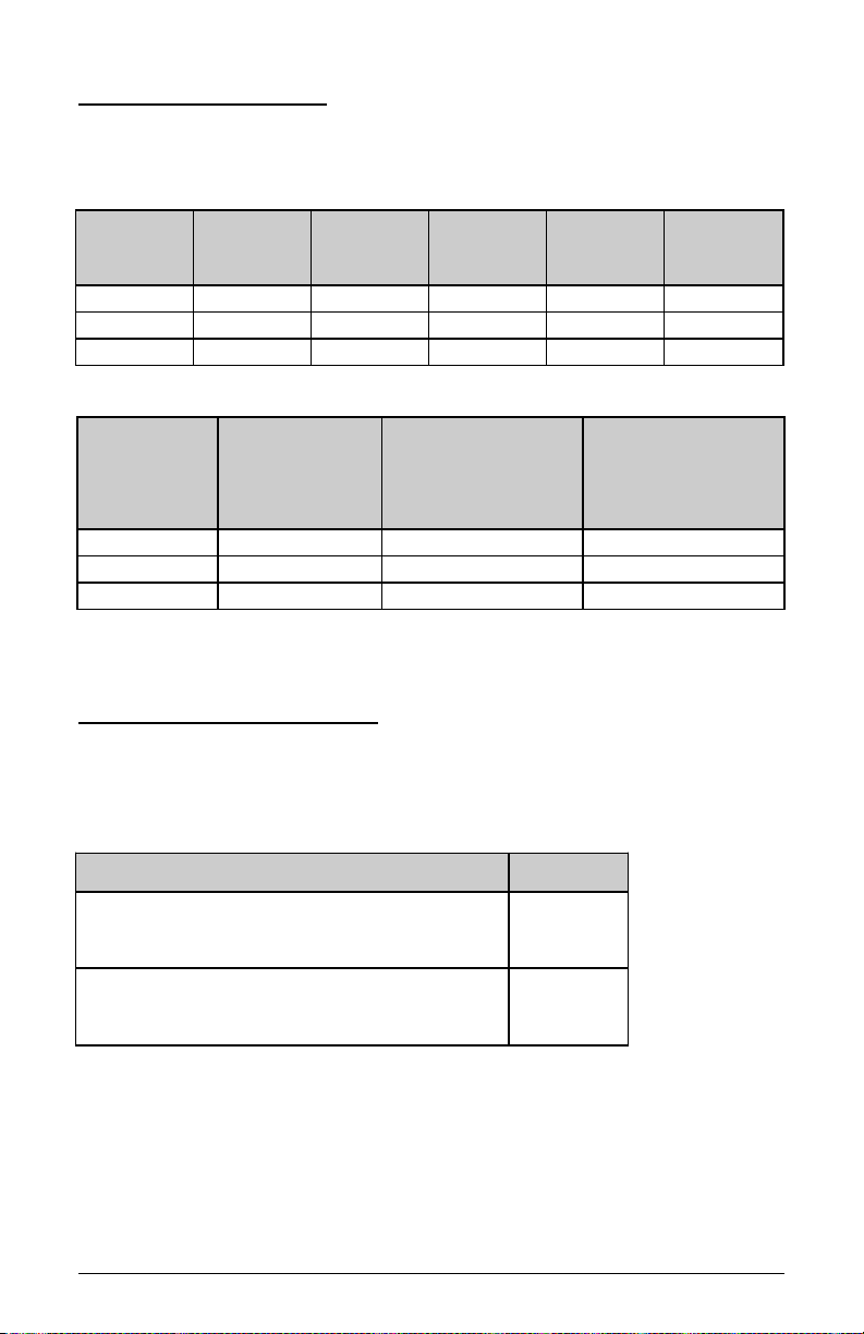
CPU Externa C ock Jumpers
If you are installing an i486DX, or i486SX the internal CPU clock speed is
the same as the external CPU clock speed. This is different for i486DX2
CPU where the external speed is one-half of the internal speed. For
example, a 486DX2-66 has an external clock speed of 33MHz.
CPU Externa
C ock Speed
JP11 JP12 JP14 JP5
20MHz OPEN OPEN SHORT 1-2
25MHz SHORT SHORT OPEN 1-2
33MHz SHORT OPEN OPEN 1-2
40MHz OPEN SHORT OPEN 2-3
50MHz OPEN OPEN OPEN 2-3
CPU Type Jumpers
CPU Type JP15 JP16 JP18 JP19
486DX, 486DX2 1-2 1-2 SHORT SHORT
487SX, ODP486SX 1-2 2-3 SHORT SHORT
486SX 2-3 OPEN OPEN SHORT
QFP486SX 2-3 OPEN OPEN OPEN
Care should be taken when installing the CPU into the Pin Grid rray
(PG ) socket on the system board. Make certain that pin 1 of the CPU
chip is correctly aligned with pin 1 of CPU socket. The location of pin 1
on the CPU is denoted by a small notch.
Page 8 486SH System Board User's Manual

Cache Size Jumpers
The system board supports 64KB/ 128KB/ 256KB of cache memory.
Cache Size Jumper Selecti n
Cache
Size
JP1 JP2 JP3 JP20 JP21
64KB 1-2 2-3 1-2 1-2 1-2
128KB 1-2 1-2 2-3 1-2 2-3
256KB 2-3 2-3 2-3 2-3 2-3
Cache Size and SRAM L cati ns
Cache
Size
Tag RAM
U36
Data Bank 0
U2,U4,U6,U
8
Data Bank 1
U1,U3,U5,U
7
64KB 8Kx8 8Kx8 8Kx8
128KB 32Kx8 32Kx8 None
256KB 32Kx8 32Kx8 32Kx8
VESA Loca Bus Jumpers
Jumper JP4 allows any VL-Bus adapter to identify the speed of the
system board.
High Speed Write JP4
System board runs one wait state write
transfer. ll VL-Bus adapters can operate
in this mode.
2-3
(Default)
System board runs zero wait state write
transfer. Some VL-Bus adapters may not
be able to run this mode.
1-2
486SH System Board User's Manual Page 9

C ear CMOS Data Jumper
The CMOS jumper JP10 is used to clear the system configuration data
currently stored in the CMOS R M. ll system setup information (hard
disk type, date/time, etc...), stored in the CMOS, will be destroyed. This
function would be useful if you were to forget the user password for the
system.
Function JP10
Normal CMOS Operation 1-2
(Default)
Clear CMOS Data 2-3
Disp ay Type Jumper
Disp ay Type JP7
Video display is VG , EG , or
Monochrome.
OPEN
(Default)
Video display is CG . SHORT
Green PC Jumper
C ock Contro JP13
Enable Green PC clock-slow-down
control. During specified idle period, CPU
clock is slowed down to 8-MHz to
conserve power.
SHORT
(Default)
Disable Green PC clock-slow-down
control. CPU is always running at full
speed.
OPEN
Page 10 486SH System Board User's Manual

SYSTEM BOARD CONNECTORS
Following is the list of 486SH system board connectors required to be
installed for proper system operation.
- Power supply connectors (CN1, CN2)
- External battery connector (J1)
- Keyboard connector (KB1)
- Power LED and keyboard lock connector (KEYLOCK)
- Speaker connector (SPE KER)
- Reset connector (RESET)
- Turbo switch connector (TB SW)
- Turbo LED connector (TB LED)
- Green PC Connectors (JP8, JP50)
Power Supp y Connectors
The two Power Supply connectors, CN1 and CN2, are 6-pin T standard
power connectors. Most power supplies have two six-wire connectors,
two of the wires on each connector are black. lign the two six-wire
connectors so that the two black wires on each connector are in the
middle as shown below.
Pin Connector CN1 Connector CN2
1 Power Good Ground
2 +5 VDC Ground
3 +12 VDC -5 VDC
4 -12 VDC +5 VDC
5 Ground +5 VDC
6 Ground +5 VDC
486SH System Board User's Manual Page 11

Externa Battery Connector
The external battery connector (J1) is a 4-pin keyed BERG strip. It is
used to connect +4.5 Volt external battery (in case the on-board battery
capsule is not installed) to provide power to the system board Real-Time
Clock and CMOS memory when the system power is off. For an external
battery, the battery's cable connector attaches to pin 1 and 4 of J1 as
shown below.
Keyboard Connector
The keyboard connector is a 5-pin, circular-type DIN socket. It is used to
connect the system board keyboard interface to any standard T-
compatible keyboard (84 or 101 -key type keyboards). The pin
assignment is shown below:
Pin Description
1 Keyboard Clock Signal
2 Keyboard Data Signal
3 Not Used
4 Ground
5 +5V Fused VDC
Page 12 486SH System Board User's Manual

Power LED and Keyboard Lock Connector
The Power LED and Keyboard Lock connector (KEYLOCK) is 5-pin
keyed BERG strip. It is used to connect +5 VDC power to the power
indicator LED at the front panel and connect security keyboard lock to the
keyboard controller. This allows you to switch off the keyboard and so
provide limited security against casual intruders. The pin assignments
are indicated below:
Pin Description
1 LED Power
2 Key (No Connection)
3 Ground
4 Keyboard Lock
5 Ground
Speaker Connector
The Speaker connector (SPE KER) is a 4-pin keyed BERG strip. It is
used to connect an external 2-inch, 8-ohm speaker to the system board
to provide sound capability. The pin assignments are defined below:
Pin Description
1 Speaker Data Out
2 Key (No Connection)
3 Ground
4 +5 VDC
486SH System Board User's Manual Page 13

Reset Connector
The system RESET connector (RESET) is a 2-pin BERG strip. It is used
to connect the push button reset switch located on the front panel to the
system board. System reset can be done by shorting pin 1 to pin 2 with
the same effect as turning the power off and then on again.
Pin Description
1 Reset Input
2 Ground
Turbo Switch Connector
The Turbo switch (TB SW) is a 2-pin BERG strip. It is used to connect
the front panel 2-position push switch to the system board speed
switching circuitry. In Turbo speed, the cache memory is enabled and full
speed of 32-bit memory transfer is utilized. In non-turbo speed, the
cache memory is disabled. In both speeds, the IS expansion bus timing
compatibility is still preserved.
Pin Description
1 Turbo Speed
2 Ground
Notes:
- System runs at Turbo speed when pins 1 and 2 are shorted.
- System runs at Slow speed when pins 1 and 2 are open.
Turbo LED Connector
The Turbo LED connector, marked as 'TB LED', is a 2-pin BERG strip. It
is used to connect a CPU operating frequency indicator LED from the
front panel to the system board. The pin assignments are indicated
below:
Pin Description
1 LED Cathode
2 LED node
Page 14 486SH System Board User's Manual

Green PC Connectors
This function requires MI Megakey keyboard controller. To program the
Green PC feature, use BIOS Power Management Setup.
Pin JP8
1 Keyboard P11. Use this pin for controlling general
purpose Green PC device. When signal on this
pin goes low, the external Green PC device
connected to this pin should go into power saving
state. This pin must be programmed through
BIOS Power Management Setup.
2 Ground
Pin JP50
1 Keyboard P12. Connect this pin to the Video
card's Feature Connector (also called VGA
Pass-Through connector) Sync Enab e
pin 18. During power saving mode (if enabled
through system BIOS), signal on this pin goes low
to turn OFF the Vertica /Horizonta Sync
going to the display monitor to conserve power.
This pin must be programmed through BIOS
Power Management Setup.
2 Keyboard P13. Use this pin for controlling general
purpose Green PC device. When signal on this
pin goes low, the external Green device
connected to this pin should go into power saving
state. This pin must be programmed through
BIOS Power Management Setup.
3 Keyboard P15. Use this pin for controlling general
purpose Green PC device. When signal on this
pin goes low, the external Green device
connected to this pin should go into power saving
state. This pin must be programmed through
BIOS Power Management Setup.
486SH System Board User's Manual Page 15

CHAPTER 3: INSTALLATION
THE DRAM SIMMs
The on-board DR M memory subsystem has eight module mounting
sockets which are divided into "banks' of four sockets each. These
banks are labeled Bank 0 and Bank 1. Single In-Line Memory Module
(SIMM) added to these banks must be installed a full bank at a time.
Start with bank 0, then work your way up. DR M speed must be 80ns,
70ns, or 60ns. You can configure the memory of the 486SH in a variety
of ways. The chart below shows the possible combinations.
Tota Memory Bank 0 Bank 1
1MB
2MB
4MB
8MB
20MB
16MB
32MB
Four 256KB SIMMs = 1MB
Four 1MB SIMMs = 4MB
Four 4MB SIMMs = 16MB
Page 16 486SH System Board User's Manual

Insta ing DRAM SIMMs
When working with DRAM
SIMMs, it is extreme y
important that you avoid
static e ectricity. A ways
ground yourse f by wearing
a wrist or ank e strap.
1. The SIMM modules should face to the left towards IS bus slots.
2. Insert the SIMM at a 45 degree angle, tilted away from the IS slots.
3. Gently push the SIMM to an upright position until it "snaps" into
place.
4. Repeat above steps until the entire bank is filled.
486SH System Board User's Manual Page 17

INSTALLING A VL-BUS CARD
Carefully follow these steps to install a VL-Bus card:
1. Turn off your computer and unplug the power cord.
2. Turn off the power to all peripheral devices, such as your printer.
3. Disconnect the cables from the back of the system in order to give
more room to work. Note how all cables are connected prior to
disconnection.
4. Remove the computer's cover.
5. Choose an unused VL-Bus slot.
6. Setting the VL-Bus card according to its user's manual.
7. Holding the card at the center of the top edge, gently push straight
down with equal pressure at both ends.
8. Replace the screw to hold the card into place.
9. Replace and secure the system cover.
10.Reconnect all the wires and cables.
EQUIPMENT REQUIRED
Page 18 486SH System Board User's Manual

The dimension of the 486SH system board is designed to fit perfectly in a
PC/XT (or PC/ T) standard case. To build a complete high performance
system based on the 486SH system board, the following equipment are
needed:
chassis with dimension similar to PC/XT/ T standard chassis.
standard T 220W power supply which is capable to provide a
continuous power within a +4.85 VDC to +5.25 VDC range. power
line filter may be needed for areas with noisy transmission.
2-inch, 8-Ohm speaker to provide sound capability.
2-position switch with a 2-pin connector for speed function.
push button switch with 2-pin connector for reset function.
One floppy drive (360K or 1.2M or 1.44M).
Hard disk drive.
combinational hard disk and floppy disk controller card.
video card (Monochrome, CG , EG , VG ).
set of flat cables between floppy drive and hard disk drive to the
combinational controller card.
n T-compatible keyboard (84 or 101 Keyboard) with cable.
video display monitor.
Following additional equipment will be useful to enhance the system:
bus or serial mouse.
tape pack up drive.
486SH System Board User's Manual Page 19

CHAPTER 4: BIOS SETUP
You need to setup a system once every time:
·You start a new and unconfigured system.
·You receive a start-up error message indicating the configuration
information stored in the non-volatile CMOS R M has somehow
become corrupted.
·You add, remove or change peripherals from your system.
The first time you power up the system, the configuration information
stored in the battery-backed CMOS R M may not be correct. The BIOS
detects this condition and prompts user to go through the SETUP section.
This chapter explains how to use the BIOS SETUP program and make
the appropriate entries.
Some of the parameters
are a ready factory preset
and do not need to be
changed. P ease read the
instructions carefu y and
on y change the settings if
necessary.
ENTERING SETUP
1. Reset the system by turning it OFF then ON or pushing the "RESET"
button on the system front panel.
2. Hit the <De > key momentarily as soon as the following message
appears:
"Hit <DEL>, if you want to run SETUP"
Page 20 486SH System Board User's Manual
Table of contents
Other Air Motherboard manuals