Air 486PH User manual

486 PCI/VL/ISA System Board
Revision 1.00
486PH System Board User s Manual Page 1

Thank you for purchasing the 486PH system board. This
document will aid you to configure and to install this system
board properly. The document is prepared with our best
knowledge; however, we make no representation or warranty
concerning the contents or use of this manual, and specifically
disclaim any expressly implied warranties or merchant ability or
fitness of any particular purpose. The information in this
document is subject to change without notice.
This document contains information protected by copyright. All
rights are reserved. No part of this document may be used or
reproduced in any form or by any means, or stored in a database
or retrieval system, without prior written permission.
. Intel is a registered trademark of Intel Corporation.
. IBM is a registered trademark of International Business
Machines Corporation.
. Microsoft is a registered trademark of Microsoft
Corporation.
. PCI is a registered trademark of PCI Special Interest
Group.
. All other trademarks used in this manual are the property of
their respective owners.

PREFACE
TRADEMARKS
TABLE OF CONTENTS
CHAPTER 1: INTRODUCTION
PRODUCT OVERVIEW
FEATURES
PRODUCT SPECIFICATIONS
CHAPTER 2: BOARD’S JUMPERS & CONNECTORS
JUMPER DESCRIPTIONS
CPU JUMPERS
CACHE MEMORY JUMPERS
SYSTEM BOARD STANDARD JUMPERS
CONNECTOR DESCRIPTIONS
PC/AT STANDARD CONNECTORS
PERIPHERAL CONNECTORS
CHAPTER 3: HARDWARE INSTALLATION
BUILDING A HIGH PERFORMANCE SYSTEM
CPU INSTALLATION
COOLING FAN INSTALLATION
INSTALLING DRAM SIMMS
DRAM SIMMS CONFIGURATION
PERIPHERAL DEVICE CONNECTION
PERIPHERAL ADD-ON CARD INSTALLATION
CHAPTER 4: SYSTEM SETUP

SYSTEM CMOS
ENTERING CMOS SETUP
SETUP WINDOW
ADVANCED SETUP
CHIPSET SETUP
POWER MANAGEMENT SETUP
UTILITY WINDOW
SECURITY SETUP WINDOW
DEFAULT SETUP WINDOW
SYSTEM BOARD CONFIGURATION
PROGRAMMING FLASH BIOS
APPENDIX A: EYBOARD HOT EYS
APPENDIX B AMI BIOS HARD DIS TYPE
APPENDIX C: ISA I/O ADDRESS MAP
APPENDIX D: MEMORY MAPPING
APPENDIX E: INTERRUPT LEVEL ASSIGNMENTS
PRODUCT INFORMATION RECORD

!
The 486PH y tem board add to our product line a highly integrated
and co t effective olution, without compromi ing performance or
quality. Intel, AMD, & Cyrix 486 CPU are upported on the
486PH y tem board. With top CPU peed at 100MHz and
integrated Write-Back cache, the 486PH dramatically boo t y tem
throughput for even the mo t demanding application .
"#
#$$%"
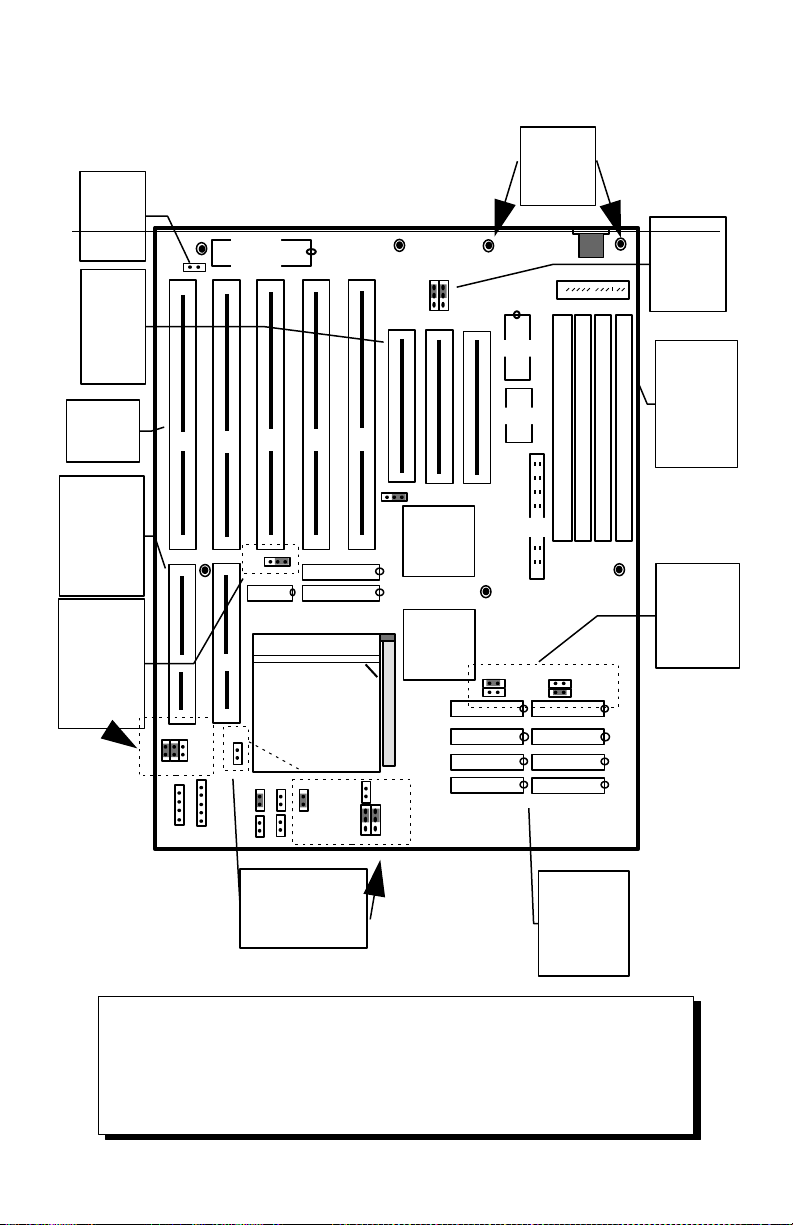
·Supports Intel, AMD, Cyrix CPUs.
&'%(
·Supports 128K, 256K, and 512K Fast External Write-back
Cache memory.
("%(
·4 Banks of Memory that support 256Kx36, 512Kx36,
1Mx36, 2Mx36, 4Mx36, & 8Mx36 72-pin SIMMs.
·Up to 64MBytes on-board memory.
("
·AMI BIOS with Built-in Window Standard CMOS,
Advanced CMOS, Advanced Chipset, Configuration
Utilities, Password, Power Management Setup Menus.
·Optional Flash BIOS supports ISA Plug & Play feature.

("')$"
·Intel ARIES EPA Green 82420EX PCI Level 2 Chipset.
·Sophisticated System Power Management.
·Supports Level 1 Write-Back CPU.
#*%"
·Three 32-bit PCI Bus Mastering slots (One is sharing slot).
·Two 32-bit VL-Bus Mastering slots.
·Five ISA slots.
+,%%"
·32-bit PCI IDE supports Mode 3 Timing.
·Support Logical Block Address to configure more than
528MB HDD.
·Auto-configuring.
*)*%&
·Real Time Clock with built-in Battery to provide accurate
timer clock.
%%&"%
·Standard PC/XT (or PC/AT) form factor and mounting
holes.

%#&"$&)-&")%+
*&")&*
Typical Power: +5V Tolerance 5%, current 4.5A.
+12V Tolerance 10%, current 100mA.
-5V Tolerance 5%, current 150mA.
-12V Tolerance 10%, current 100mA.
+.)%++"*
Operating temperature (ambient): O0C/320F to 550C/1310F
Storage temperature -200C/-40F to 700C/1580F
Operating Humidity: 10% to 90%
(non-condensing)
Storage Humidity: 5% to 95%
(non-condensing)
)+)%+
Width: 8.7 inches (221.0 mm)
Length: 10.8125 inches (274.5 mm)

/012
When working with the 486PH, it is extremely
important that you avoid
Electrical Static Discharge (ESD).
Always ground yourself by wearing a
grounded wristband or ankle strap.
Figure 1 on the next page shows the component layout of the
486PH system board with locations of the system board jumpers
and connectors. Note that most of the jumpers and connectors
on the system board are labeled with proper names with pin 1
marked as . To avoid damaging the board and to ensure proper
operation, caution should be taken when connecting these
jumpers and connectors.
1
Jumpers are used to select between various operating modes. A
jumper switch consists of two, three, or four gold pins projecting
from the system board. Placing the plastic jumper cap over two
pins connects those pins and makes a particular selection. Using
the jumper cap to cover two pins in this way is referred to as
shorting those pins. If the cap is not placed on any pins at all or
placed on only one pin, this is referred to as leaving the pins
open.
Note: When you open a jumper, leave the plastic jumper cap
attached to one of the pins so you don t lose it.
1 2 3

Remark: The sample jumper setting
shown above is set at 486DX-33M z, 256K
Cache Size.
Remark: The sample jumper setting
shown above is set at 486DX-33M z, 256K
Cache Size.
S
I
M
M
3
S
I
M
M
4
S
I
M
M
1
S
I
M
M
2
CPU Clock
Speed
Selection
Jumpers
JP6, JP19,
JP20,
& J P21
eyboard Connector
Intel
Aries
S82426EX
CPU Type
Selection Jumpers:
JP10, JP16, J P23,
JP24, JP25
eyboar
d
Controlle
r
BIO
S
Power Connectors
Intel
Aries
S82425EX
1
1
ID
E
LOC
HDLE
D
SP R RESE
T
TURB
O
TBLE
D
1
JP6
JP19
JP20
JP21
JP11
12C887A
JP1
6
JP2
5
1
JP2
4
JP
2
JP1
JP1
0
1
JP1
2
JP8
JP9
JP3
1
JP2
3
11
JP1
4
1
1
Figure 1: 486PH Component ayout
Cache
Memory
up to
512 B
Three
32-bit
PCI local
bus
mastering
slots
Five 16-bit
ISA slots
Two 32-bit
VESA
standard
local bus
mastering
slots
Four 72-Pin
SIMM socket
support up
to 64 Mbytes
CMOS
Discharge
Jumper JP1
Holes for
Plastic
mountings
or screws
Cache Size
Jumpers:
JP8, JP9,
JP11 & JP12
Monitor
Selection
Jumper:
J P2
CP
U

1#$
($*&")%+1#$
CPU Type JP10 JP16 JP23 JP24 JP25
Intel 486SX Short Open Open 2-3 1-2
Intel 486DX, DX2,
DX4 (Default)
Short Open Open 1-2 1-2
AMD 486DX,
DX4*
Short Open Short 1-2 2-3
AMD 486DX2* Short Open Open 1-2 2-3
Cyrix 3.3-Volt
486DX, DX2
Short Short Short 1-2 2-3
Cyrix 5-Volt
486DX, DX2
Short Open Short 1-2 2-3
* Chipset auto detects AMD 3.3-Volt and 5-Volt CPUs, no
special jumper setting is required.
*%&3#+&(*&")%+1#$
If you are installing an 486DX or 486SX CPU, the internal CPU
clock speed is the same as the external CPU clock speed. This is
different for 486DX2 CPU where the external speed is one-half
of the internal speed. For example, a 486DX2-66 has an
external clock speed of 33MHz.
Clock
Frequency
CPU supported JP6 JP19 JP20 JP21
33 MHz 486SX-33
487SX-33
486DX-33
486DX2-66
486DX4-100
P24T
1-2 Open Short Short
25MHz 486SX-25
487SX-25
486DX-25
486DX2-50
486DX4-75
2-3 Short Open Open

&'%(1#$
&'%()41#$
Three cache memory sizes are supported. The jumpers are set
according to the size of Cache Memory installed.
Cache Size JP8 JP9 JP11 JP12
128KB Short Open Open Open
256KB Open Short Short Open
256KB* Short Open Short Open
512KB Short Open Short Short
&'+"**")%+5*
Cache Size U23, U26, U29, U31 U24, U27, U30, U32 U13 & U16
128KB 32Kx8 None 32Kx8
256KB 32Kx8 32Kx8 32Kx8
256KB* 64Kx8 None 32Kx8
512KB 128Kx8 None 32Kx8
* If 256KB with 64Kx8 SRAM type is installed, in the BIOS
CMOS Chipset Setup menu, L2 Cache Configuration must
set to N-Leaved.

("%"+1#$
)&'61#$
The jumper JP1 is used to clear all information, including
password that are currently stored in the CMOS RAM. (ODIN
OEC12C887A on 486PH board.). It is typically used when you
forget the password that you selected previously and you cannot
get into CMOS setup menu.
Function JP1
Normal Operation (Default) 1-2
Clear CMOS Data 2-3
%+)"%($*&"1#$
This is PC/AT compatible jumper to inform the system BIOS
that the graphic card installed is CGA type or EGA, VGA, and
Monochrome type. Thus, the jumper should be set accordingly
to the type of graphic card installed in the system.
Display Type JP2
VG , EG , or Monochrome (Default) Open
CGA Short
1#$
#+&")%+
Enable TURBO mode (Default) Short
Disable TURBO mode. Open

+#7&"#.1#$
The jumper setting show below are factory installed.
Manufacturer has reserved these jumpers. No modification is
allowed.
Jumper Setting
JP3 1-2
JP14 1-2

Following is the list of 486PH system board connectors required to
be installed for proper system operation. For detailed descriptions
of these components, please refer to the next section. To avoid
damaging the board and to have proper operation, caution should be
taken when connecting these components.
- Power supply connectors (PS1 and PS2)
- Keyboard connector (CN1)
- Reset connector (RESET)
- Power LED and keyboard lock connector (KLOCK)
- Speaker connector (SPKR)
- Turbo Switch connector (TURBO)
- Turbo LED connector (TBLED)
- Hard Disk Activity LED connector (HDLED)
- IDE Interface connector (IDE1)

8"+%++&"%
%9#$$*(%++&"%:+/;
The two Power Supply connectors (PS1 and PS2) are 6-pin AT
standard power connectors. Most power supplies have two six-
wire connectors, two of the wires on each connector are black.
Align the two six-wire connectors so that the two black wires on
each connector are in the middle as shown below.
)+ %++&"%/ %++&"%
1 Power Good Ground (Black)
2 +5 VDC Ground (Black)
3 +12 VDC -5 VDC
4 -12 VDC +5 VDC
5 Ground (Black) +5 VDC
6 Ground (Black) +5 VDC
Black

<(5%%++&"%
The keyboard connector (CN1) is a 5-pin, circular-type DIN
socket. It is used to connect the system board keyboard
interface to any standard AT-compatible keyboard. (84 or 101 -
key type keyboards). The pin assignments are listed below:
)+ &)$")%+
1 Keyboard Clock Signal
2 Keyboard Data Signal
3 Not Used
4 Ground
5 +5V Fused VDC
"%++&"%
The system RESET connector (RESET) is a 2-pin BERG strip.
It is used to connect the push button reset switch located on the
front panel to the system board. System reset can be done by
shorting pin 1 to pin 2 with the same effect as turning the power
off and then on again.
)+ &)$")%+
1 Ground
2 Reset Input

%9+<(5%%&%++&"%
The Power LED and Keyboard Lock connector (KLOCK) is 5-
pin keyed BERG strip. It is used to connect +5 VDC power to
the power indicator LED at the front panel and connect security
keyboard lock to the keyboard controller. This allows you to
switch off the keyboard and so provide limited security against
casual intruders. The pin assignments are indicated below:
)+ &)$")%+
1 Power LED
2 Key (No Connection)
3 Ground
4 Keyboard Lock
5 Ground
$%++&"%
The Speaker connector (SPKR) is a 4-pin keyed BERG strip. It
is used to connect an external 2-inch, 8-ohm speaker to the
system board to provide sound capability. The pin assignments
are defined below:
)+ &)$")%+
1 Speaker Data Out
2 Key (No Connection)
3 Ground
4 +5 VDC

#5%9)"&'%++&"%
The Turbo switch (TURBO) is a 2-pin BERG strip. It is used to
connect the front panel 2-position push switch to the system
board speed switching circuitry. The Turbo mode is set as
default on the 486PH.
Function TURBO
Enable TURBO Mode (Default) Short
Disable TURBO Mode Open
#5%%++&"%
The Turbo LED connector (TBLED) is a 2-pin BERG strip. It is
used to connect a CPU operating frequency indicator LED from
the front panel to the system board. The pin assignments are
indicated below:
)+ &)$")%+
1 LED Cathode ( - )
2 LED Anode (+)
)&").)"(%++&"%
The hard disk activity LED connector (label as HDLED) is a 2-
pin keyed BERG strip. The LED will be on whenever there is
data transfer activity on on-board IDE bus. The connector
should be connected to the case’s front panel hard disk LED.
)+ &)$")%+
1 LED Anode (+)
2 LED Cathode (-)

)$'*%++&"%
+"7&%++&"%
The on-board 32-bit PCI IDE Interface connector (IDE1) is a
2x20-pin male header. This interface supports up to two hard
disk drives on the system. Pin assignment of IDE is as follow:
)+ &)$")%+ )+ &)$")%+
2 Ground 1 IDE Reset/
4 Data 8 3 Data 7
6 Data 9 5 Data 6
8 Data 10 7 Data 5
10 Data 11 9 Data 4
12 Data 12 11 Data 3
14 Data 13 13 Data 2
16 Data 14 15 Data 1
18 Data 15 17 Data 0
20 No Connection 19 Ground
22 Ground 21 No Connection
24 Ground 23 I/O Write/
26 Ground 25 I/O Read/
28 ALE 27 No Connection
30 Ground 29 No Connection
32 IOCS16/ 31 IDE IRQ 14
34 No Connection 33 Address A1
36 Address A2 35 Address A0
38 IDE Chip Select 1/ 37 IDE Chip Select 0/
40 Ground 39 IDE Active/

=!
>>?
The dimensions of the 486PH system board are designed to fit
perfectly in a PC/XT (or PC/AT) standard case. To build a
complete high performance system based on the 486PH system
board, the following equipment are needed:
1. A chassis with dimensions similar to PC/XT/AT standard
chassis. The chassis should have a front panel with
connectors for Reset, Power, Keylock, Turbo switch,
Turbo LED, Speaker. AC power cable should be
included with the chassis. A standard AT 230W power
supply should be capable of providing a continuous
power within a +4.75 VDC to +5.25 VDC range. A
power line filter may be needed for areas with noisy
transmission.
2. One or two floppy drives (360K/1.2M/1.44M/2.88M).
3. SCSI Hard disk drive or IDE hard disk drive with a hard
disk controller.
4. Video card (Monochrome, CGA, EGA, VGA).
5. A video display monitor.
6. An AT-compatible keyboard (84 or 101 Keyboard).
7. The following additional peripherals will be useful to
enhance the system:
·A bus or serial mouse.
·A tape back up drive.
·A CD-ROM drive.
8. Cables
·A set of flat cables for floppy drive and hard disk drive.
·AC Power cable (Usually Comes with power supply in
case)
9. Tools
·Set of Screw drivers, Cutter, Pliers
Table of contents
Other Air Motherboard manuals