Air 486MI User manual

PREFACE
Thank you for purchasing the 486MI system board. This document gives
an aid to the configuration and installation of this system board.
The information in this document is subject to change without notice.
This document contains information protected by copyright. ll rights are
reserved. No part of this document may be used or reproduced in any
forms or by any means, or stored in a database or retrieval system,
without prior written permission.
TRADEMARKS
Intel is a registered trademark of Intel Corporation.
IBM is a registered trademark of International Business Machines
Corporation.
Microsoft is a registered trademark of Microsoft Corporation.
VES is a registered trademark of Video Electronics Standard
ssociation.
ll other trademarks used in this manual are the property of their
respective owners.
486MI System Board User's Manual Page 1

TABLE OF CONTENTS
CHAPTER 1: INTRODUCTION 4
CHAPTER 2: JUMPERS & CONNECTORS 6
SYSTEM BOARD JUMPERS 6
CPU External Cl ck Jumpers 8
CPU Type Jumpers 8
Cache Size Jumpers 9
VESA L cal Bus Jumper 9
Clear CMOS Data Jumper 10
Display Type Jumper 10
FLASH BIOS Jumper 11
IDE P rt Jumpers 12
Parallel P rt Jumper 12
SYSTEM BOARD CONNECTORS 13
Green PC C nnect rs 13
P wer Supply C nnect rs 14
Keyb ard C nnect r 15
P wer LED and Keyb ard L ck C nnect r 15
Speaker C nnect r 16
Reset C nnect r 16
Turb Switch C nnect r 17
Turb LED C nnect r 17
Parallel P rt C nnect r 18
Serial P rt 1 & 2 C nnect rs 18
Fl ppy Interface C nnect r 19
IDE Interface C nnect r 20
Harddisk Activity LED C nnect r 20
CHAPTER 3: HARDWARE INSTALLATION 21
THE DRAM SIMMs 21
Installing DRAM SIMMs 22
INSTALLING A VL-BUS CARD 23
EQUIPMENT REQUIRED 24
CHAPTER 4: BIOS SETUP 25
ENTERING SETUP 25
STANDARD CMOS SETUP 27
ADVANCED CMOS SETUP 28
POWER MANAGEMENT SETUP 32
AUTO CONFIGURATION - BIOS DEFAULTS 32
AUTO CONFIGURATION - POWER-ON DEFAULTS 32
CHANGE PASSWORD 33
AUTO DETECT HARD DISK 34
HARD DISK UTILITY 34
WRITE TO CMOS AND EXIT 34
DO NOT WRITE TO CMOS AND EXIT 34
CHAPTER 5: VL-BUS IDE DRIVERS 35
Page 2 486MI System Board User's Manual

DOS DRIVER INSTALLATION 35
WINDOWS 3.1 DRIVER INSTALLATION 35
CHAPTER 6: KEYBOARD HOT KEYS 37
SYSTEM SPEED 37
SYSTEM SECURITY LOCKING 37
SYSTEM POWER DOWN MODE 37
PASSWORD STATE 38
APPENDIX A: AMI BIOS HARD DISK TYPE 39
APPENDIX B: MEMORY MAPPING 40
APPENDIX C: AT I/O ADDRESS MAP 41
APPENDIX D: INTERRUPT ASSIGNMENTS 43
APPENDIX E: SPECIFICATION 44
486MI System Board User's Manual Page 3

CHAPTER 1: INTRODUCTION
The 486MI system board adds to our 486 product line high integration
and cost effective solution without compromising performance and
quality. With top speed at 50MHz and integrated 64K/128K/256K Write-
Back cache, the 486MI dramatically boosts system throughput for even
the most demanding applications. The 486MI offers features and
functionality exceeding any other system board in its class, including:
CPU:
·Intel i486DX, i486DX2, i486SX, i487SX, P24T, and Overdrives.
Cache Memory:
·Supports 64K/128K/256K/512K cache memory.
Main Memory:
·Supports 512Kx36, 1Mx36, 2Mx36, 4Mx36, and 8Mx36 72-pin SIMM
modules.
·Up to 64 MBytes on-board memory.
S ots:
·Three 32-bit VES Local Bus (VL-Bus) slots. ll slots support Bus
Master operation.
·Seven 16-bit IS bus slots.
IDE Port:
·Turbo/Normal selections for fast or slow IDE hard drives.
·Plug and play, replaces any non-intelligent IDE controller without
reformatting the disk drives.
·Software drivers are not required for all operating systems.
Page 4 486MI System Board User's Manual

F oppy Disk Contro er:
·Fully IBM register set compatible.
·Supports up to two 3.5-inch or 5.25-inch floppy disk drives.
·Supports 360KB / 720KB / 1.2MB / 1.44MB densities.
·Floppy Disk Controller can be disabled.
Periphera s:
·Supports two Serial ports, one Parallel port and one Game port.
Green PC:
·CPU clock-slow-down and monitor shut-down features.
On-Board Battery:
·3.6V/60m on-board battery.
486MI System Board User's Manual Page 5

CHAPTER 2: JUMPERS & CONNECTORS
When working with the 486MI, it
is extreme y important that you
avoid static e ectricity. A ways
ground yourse f by wearing a
wrist or ank e strap.
Figures 1 on the next page shows the component layout of the 486MI
system board with locations of the system board jumpers and
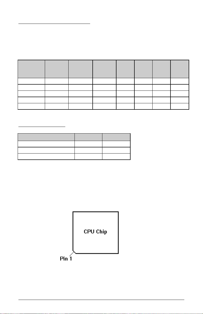
connectors. Note that most jumpers and connectors on the system board
are labeled with proper names with pin 1 marked as '1'. To avoid
damaging the board and to have proper operation caution should be
taken when connecting these components.
SYSTEM BOARD JUMPERS
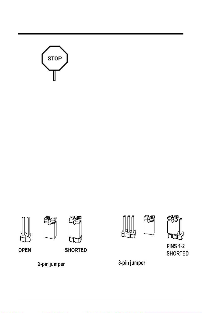
Jumpers are used to select between various operating modes. jumper
switch consists of two, three, or four gold pins projecting from the system
board. Placing the plastic jumper cap over two pins connects those pins
and makes a particular selection. Using the cap to cover two pins in this
way is referred to as shorting those pins. If the cap is not placed on any
pins at all, this is referred to as leaving the pins open.
Note: When you open a jumper, leave the plastic jumper cap attached
to one of the pins so you don't lose it.
Page 6 486MI System Board User's Manual

FIGURE
486MI System Board User's Manual Page 7

CPU Externa C ock Jumpers
If you are installing an i486DX or i486SX, the internal CPU clock speed is
the same as the external CPU clock speed. This is different for i486DX2
CPU where the external speed is one-half of the internal speed. For
example, a 486DX2-66 has an external clock speed of 33MHz.
Externa
C ock
Speed
JP5
JP6 JP7 ID3 JP26 JP27 JP28
20MHz SHORT OPEN OPEN 1-2 2-3 2-3 1-2
25MHz OPEN SHORT SHORT 1-2 2-3 2-3 1-2
33MHz OPEN SHORT OPEN 1-2 2-3 2-3 1-2
40MHz OPEN OPEN SHORT 2-3 1-2 1-2 2-3
50MHz OPEN OPEN OPEN 2-3 1-2 1-2 2-3
CPU Type Jumpers
CPU Type JP1 JP2
486DX, 486DX2 1-2 1-2, 3-4
487SX, ODP486SX 2-3 1-2, 3-4
486SX OPEN 2-3
Care should be taken when installing the CPU into the Pin Grid rray
(PG ) socket on the system board. Make certain that pin 1 of the CPU
chip is correctly aligned with pin 1 of CPU socket. The location of pin 1
on the CPU is denoted by a small notch.
Page 8 486MI System Board User's Manual

Cache Size Jumpers
The system board supports 64KB/ 128KB/ 256KB/ 512KB of cache
memory.
Cache Size Jumper Selecti n
Cache
Size
JP10 JP11 JP12 JP13 JP14 JP15
64KB 1-2 1-2 1-2 2-3 1-2 1-2
128KB 2-3 1-2 1-2 1-2 1-2 2-3
256KB 2-3 2-3 1-2 2-3 2-3 2-3
256KB 2-3 2-3 2-3 1-2 1-2 2-3
Cache Size and SRAM L cati ns
Cache
Size
Tag RAM
U14
Data Bank 0
U19,U20,
U21,U22
Data Bank 1
U23, U24,
U25, U26
64KB 8Kx8 8Kx8 8Kx8
128KB 32Kx8 32Kx8 None
256KB 32Kx8 32Kx8 32Kx8
512KB 32Kx8 128Kx8 None
VESA Loca Bus Jumper
Jumper ID2 allows any VL-Bus adapter to identify the speed of the
system board.
High Speed Write ID2
System board runs one wait state write
transfer. ll VL-Bus adapters can operate
in this mode.
2-3
(Default)
System board runs zero wait state write
transfer. Some VL-Bus adapters may not
be able to run this mode.
1-2
486MI System Board User's Manual Page 9

C ear CMOS Data Jumper
The CMOS jumper JP20 is used to clear the system configuration data
currently stored in the CMOS R M. ll system setup information (hard
disk type, date/time, etc...), stored in the CMOS, will be destroyed. This
function would be useful if you were to forget the user password for the
system.
Function JP20
Normal CMOS Operation 1-2
(Default)
Clear CMOS Data 2-3
Follow these steps to clear CMOS data:
1. Turn power OFF.
2. Open the system cover and gain access to jumper JP20.
3. Change jumper JP20 to 2-3 position for few seconds then move the
jumper block back to 1-2 position again.
4. Replace and secure the system cover.
5. Turn power ON, CMOS data should be cleared.
Disp ay Type Jumper
Disp ay Type JP16
Video display is VG , EG , or
Monochrome.
OPEN
(Default)
Video display is CG . SHORT
Page 10 486MI System Board User's Manual

FLASH BIOS Jumper
FL SH BIOS is an optional feature, contact our sale representatives for
detail.
FLASH BIOS Contro JP17
Disable FL SH (optional) programming.
This is normal operation.
1-2
(Default)
Enable FL SH BIOS programming.
Contents of system board BIOS can be re-
programmed.
2-3
Follow these steps to reprogram Flash BIOS:
1. Turn power OFF.
2. Open the system cover and gain access to jumper JP17.
3. Change jumper JP17 to 2-3 position.
4. Turn power ON and disable External Cache through BIOS dvanced
CMOS Setup.
5. Reboot the system and run MIFL SH.COM program from the
Driver Diskette. Follow the screen instructions.
6. fter programming is complete, turn power OFF and change jumper
JP17 back to 1-2 position.
7. Turn power ON again. BIOS message with new revision number will
appear on screen.
8. Re-enable External Cache through BIOS Setup.
486MI System Board User's Manual Page 11

IDE Port Jumpers
IDE Enab e/Disab e JP29
Enable on-board VL-Bus IDE port. 1-2
(Default)
Disable on-board VL-Bus IDE port. 2-3
JP22 JP23 JP24 VL-Bus
C ock
IDE Recovery Time
2 - 3
1 - 2
2 - 3
1 - 2
2 - 3
2 - 3
2 - 3
2 - 3
2 - 3
t 33MHz
or less
9T, Low Speed (Default)
7T, Middle Speed
5T, High Speed
2 - 3
1 - 2
2 - 3
2 - 3
1 - 2
1 - 2
1 - 2
2 - 3
2 - 3
t 40MHz
or more
13T, Low Speed
11T, Middle Speed
9T, High Speed
Para e Port Jumper
Para e Port JP30
Select interrupt line IRQ7 for Parallel port. 1-2
(Default)
Select interrupt line IRQ5 for Parallel port. 2-3
Page 12 486MI System Board User's Manual

SYSTEM BOARD CONNECTORS
Green PC Connectors
Descriptions W1
pins
W1
pins
Descriptions
No Connection. 1 6 Keyboard P12 to control
video card VSYNC. This
pin should be connected
to pin 12 of VG Feature
connector.
Keyboard P12 to enable/
disable video signals.
This pin should be
connected to pin 18 of
VG Feature connector.
2 7 Keyboard P12 to control
video card HSYNC. This
pin should be connected
to pin 11 of VG Feature
connector.
Keyboard P13 (General
Purpose). When this pin
is at low level, it can
switch other system
device to stand-by mode
for saving power.
3 8 No Connection.
Keyboard P10 (General
Purpose). When this pin
is at low level, it can
switch other system
device to stand-by mode
for saving power.
4 9 Power Stand-By Mode
LED pull-up. Connect a
LED to pin 9 and 10.
When the LED light is on,
power saving mode is
engaged.
Ground 5 10 Keyboard P11 to turn on
stand-by mode LED.
System power down can be invoked by shorting pin 1 to pin 2 of jumper
"GREEN" located near CPU. Make sure the BIOS Power Management
Setup options are enabled. Connect a 2-position switch from the front
panel to this jumper for manual control.
486MI System Board User's Manual Page 13

Power Supp y Connectors
The two Power Supply connectors are 6-pin T standard power
connectors. Most power supplies have two six-wire connectors, two of
the wires on each connector are black. lign the two six-wire connectors
so that the two black wires on each connector are in the middle as shown
below.
Pin Connector PS2 Connector PS1
1 Power Good Ground
2 +5 VDC Ground
3 +12 VDC -5 VDC
4 -12 VDC +5 VDC
5 Ground +5 VDC
6 Ground +5 VDC
Page 14 486MI System Board User's Manual

Keyboard Connector
The keyboard connector is a 5-pin, circular-type DIN socket. It is used to
connect the system board keyboard interface to any standard T-
compatible keyboard (84 or 101 -key type keyboards). The pin
assignments are listed below:
Pin Description
1 Keyboard Clock Signal
2 Keyboard Data Signal
3 Not Used
4 Ground
5 +5V Fused VDC
Power LED and Keyboard Lock Connector
The Power LED and Keyboard Lock connector (KLOCK) is 5-pin keyed
BERG strip. It is used to connect +5 VDC power to the power indicator
LED at the front panel and connect security keyboard lock to the
keyboard controller. This allows you to switch off the keyboard and so
provide limited security against casual intruders. The pin assignments
are indicated below:
Pin Description
1 LED Power
2 Key (No Connection)
3 Ground
4 Keyboard Lock
5 Ground
486MI System Board User's Manual Page 15

Speaker Connector
The Speaker connector (SPKR) is a 4-pin keyed BERG strip. It is used
to connect an external 2-inch, 8-ohm speaker to the system board to
provide sound capability. The pin assignments are defined below:
Pin Description
1 Speaker Data Out
2 Key (No Connection)
3 Ground
4 +5 VDC
Reset Connector
The system RESET connector (RESET) is a 2-pin BERG strip. It is used
to connect the push button reset switch located on the front panel to the
system board. System reset can be done by shorting pin 1 to pin 2 with
the same effect as turning the power off and then on again.
Pin Description
1 Reset Input
2 Ground
Page 16 486MI System Board User's Manual

Turbo Switch Connector
The Turbo switch (TURBO) is a 2-pin BERG strip. It is used to connect
the front panel 2-position push switch to the system board speed
switching circuitry. In Turbo speed, the cache memory is enabled and full
speed of 32-bit memory transfer is utilized. In non-turbo speed, the
cache memory is disabled. In both speeds, the IS expansion bus timing
compatibility is still preserved.
Pin Description
1 Turbo Speed
2 Ground
Notes:
- System runs at Turbo speed when pins 1 and 2 are shorted.
- System runs at Slow speed when pins 1 and 2 are open.
Turbo LED Connector
The Turbo LED connector, marked as 'TB/LED', is a 2-pin BERG strip. It
is used to connect a CPU operating frequency indicator LED from the
front panel to the system board. The pin assignments are indicated
below:
Pin Description
1 LED Cathode
2 LED node
486MI System Board User's Manual Page 17

Para e Port Connector
The on-board parallel port connector (P R LL) is a 2x13-pin male
header connector. The pin assignment is shown below:
Pin Description Pin Description
1 -STROBE 14 - UTO FEED XT
2 Data Bit 0 15 -ERROR
3 Data Bit 1 16 -INIT
4 Data Bit 2 17 -SLCT IN
5 Data Bit 3 18 Ground
6 Data Bit 4 19 Ground
7 Data Bit 5 20 Ground
8 Data Bit 6 21 Ground
9 Data Bit 7 22 Ground
10 - CK 23 Ground
11 -BUSY 24 Ground
12 PE 25 Ground
13 SLCT 26 No Connection
Seria Port 1 & 2 Connectors
The serial port 1 and 2 connectors are the 2x5-pin male headers COM1
and COM2. Users should use a flex cable with a 9 or 25 -pin male D-
subminiature receptacle at one end and a 2x5-pin female header at the
other end to provide RS-232 serial interface. The pin assignment for
COM1/COM2 is defined below:
Pi
n
Description Pi
n
Description
1 Carrier Detect (RLSD) 6 Receive Data (RXD)
2 Transmit Data (TXD) 7 Data Terminal Ready (DTR)
3 Signal Ground 8 Data Set Ready (DSR)
4 Request To Send (RTS) 9 Clear To Send (CTS)
5 Ring Indicator (RI) 10 No Connection
Page 18 486MI System Board User's Manual

F oppy Interface Connector
The on-board Floppy Interface connector (FLOPPY) is a 2x17-pin male
header. This interface supports two 5.25" or 3.5" floppy drives in any
combination and also can be disabled if no floppy drives are present on
the system.
Pin Description Pin Description
2 RPM 1 Ground
4 No Connection 3 Ground
6 No Connection 5 Ground
8 Index 7 Ground
10 Motor 1 9 Ground
12 Drive 2 11 Ground
14 Drive 1 13 Ground
16 Motor 2 15 Ground
18 Direction 17 Ground
20 Step 19 Ground
22 Write Data 21 Ground
24 Write Enable 23 Ground
26 Track0 25 Ground
28 Write Protect 27 Ground
30 Read Data 29 Ground
32 Head Select 31 Ground
34 Disk Change 33 Ground
486MI System Board User's Manual Page 19

IDE Interface Connector
The on-board IDE Interface connector (IDE) is a 2x20-pin male header.
This interface supports up to two IDE hard disk drives on the system.
This interface can also be disabled in the event that no hard drive is
present or a separate hard drive controller is installed on the system.
Pin Description Pin Description
2 Ground 1 IDE Reset/
4 Data 8 3 Data 7
6 Data 9 5 Data 6
8 Data 10 7 Data 5
10 Data 11 9 Data 4
12 Data 12 11 Data 3
14 Data 13 13 Data 2
16 Data 14 15 Data 1
18 Data 15 17 Data 0
20 No Connection 19 Ground
22 Ground 21 No Connection
24 Ground 23 I/O Write/
26 Ground 25 I/O Read/
28 LE 27 No Connection
30 Ground 29 No Connection
32 IOCS16/ 31 IDE IRQ 14
34 No Connection 33 ddress 1
36 ddress 2 35 ddress 0
38 IDE Chip Select 1/ 37 IDE Chip Select 0/
40 Ground 39 IDE ctive/
Harddisk Activity LED Connector
The hard disk activity LED connector (HDLED) is a 2-pin keyed BERG
strip. It is used to connect to front panel hard disk LED.
Pin Description
1 LED node (+)
2 LED Cathode (-)
Page 20 486MI System Board User's Manual
Table of contents
Other Air Motherboard manuals